Advertisement
Quick Links
Flight Test Team-11/19/2019
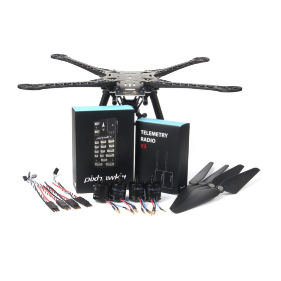
The Pixhawk 4 S500 V2 Basic Kit is the perfect way to get started developing on
Pixhawk 4. It pairs a 480mm wheelbase frame and essential electronics with a
Pixhawk 4 autopilot.
Bill of materials
•
Pixhawk 4 autopilot(PM07 not included)
•
Power Management PM02(Assembled)
•
ARM adopts high strength plastics
•
Motors - 2216 KV880( V2 Update)
•
Propeller 1045( V2 Update)
•
Pixhawk4 GPS
•
Fully assembled Power Management Board with ESCs
•
433MHz Telemetry Radio / 915MHz Telemetry Radio
•
Power and Radio Cables
•
Battery Straps
•
Dimensions:383*385*240mm
•
Wheelbase:480mm
Not included: RC transmitter and receiver, LiPo battery (suitable for 3s to 4s LiPo (3000 to 5000
mAh) we use a FrSky Taranis controller. You will also need zip ties, double-sided tape, a
Advertisement

Related Manuals for Holybro Pixhawk 4 S500 V2 Basic Kit

Summary of Contents for Holybro Pixhawk 4 S500 V2 Basic Kit
- Page 1 Flight Test Team-11/19/2019 The Pixhawk 4 S500 V2 Basic Kit is the perfect way to get started developing on Pixhawk 4. It pairs a 480mm wheelbase frame and essential electronics with a Pixhawk 4 autopilot. Bill of materials • Pixhawk 4 autopilot(PM07 not included)...
- Page 2 soldering iron. The image below shows both frames and electronic components.
-
Page 3: Item Description
Hardware This section lists all hardware for the frame and the autopilot installation. Item Description Quantity Wheelbase:480mm Arms Set of Landing Gear M3*8 screws M2 5*6 screws Battery Straps Propeller 1045( V2 Update) Pixhawk 4 Package Details Items Package Pixhawk 4 Pixhawk4 GPS MODULE I2C splitter Board 6 to 6 pin cable (power) - Page 4 10 to 10 pin cable (PWM) 8 to 8 pin cable(AUX) 7 to 7 pin cable(SPI) 6 to 6 pin cable(Debug) PPM/SBUS out cable XSR receiver cable DSMX receiver cable SBUS receiver cable USB cable 'X'type folding pedestal mount 70mm & 140mm carbon rod standoff 6*3 2.54mm pitch Horizontal Pin 8*3 2.54mm pitch Horizontal Pin Foam Set...
- Page 5 Pixhawk 4 autopilot(PM06 not included) Power Management PM02(Assembled) Motors - 2216 KV880( V2 Update Pixhawk 4 GPS Fully assembled Power Management Board with ESCs 433MHz Telemetry Radio / 915MHz Telemetry Radio Tools Needed • 1.5 mm Hex screwdriver • 2.0 mm Hex screwdriver •...
- Page 6 Estimated time for the complete setup is 90 minutes, the frame is about 45 minutes and 45 minutes installing the autopilot and configuring the airframe in QGroundControl. Frame assembly Step 1: Assembling the Landing Gear We are going to start by assembling the landing gear to the vertical pole. Unscrew the landing gear screws and insert the vertical pole, see Figures 1 and 2.
- Page 7 Figure 2 Step 2: Assemble the Power Management Board to the landing gear. Screw the landing gear with a vertical pole to the Fully assembled Power Management Board. The Board has 4 holes (see Figure 3 arrows) use the M3X8 screws, a total of 8 pieces, 4 on each side, see Figure 4.
- Page 8 Figure 3...
- Page 9 Figure 4 Figure 5 Step 3: Assemble the arms to the Power Management Board. Attach the arm to the Power Management Board, see Figures 6 and 7. Use M2 5X6 screws a total of 2 in each arm. Insert the screws from the bottom of the plate, see Figure 8. Make sure the ESC cables run through the middle of the arm, see Figure 9.
- Page 10 Figure 6...
- Page 11 Figure 7...
- Page 12 Figure 8...
- Page 13 Figure 9 Step 4: Assemble the 8*3 2.54mm pitch Horizontal Pin to the 10 to 10 pin cable (PWM) to the Power Management Board. Connect the 10 to 10 pin cable (PWM) to the 8*3 2.54mm pitch Horizontal Pin, see Figure 10.
- Page 14 Figure 10...
- Page 15 Figure 11...
- Page 16 Figure 12...
- Page 17 Figure 13 Step 5: Assemble the motors to the arms. For this, we will need the 16 screws M3X7, 4 motors, and the 4 arms. Mount the motors in each arm put the screw through the bottom of the arm, see Figures 14 and 15. After the 4 motors are mounted on the arm grab the cables(red, blue, black) and put them through the arm thread, see Figures 16 and 17.
- Page 18 Figure 14...
- Page 19 Figure 15...
- Page 20 Figure 16...
- Page 21 Figure 17 Step 6: Mounting the GPS on the frame. For this, we will need the Pixhawk 4 GPS and the mounting plate, see Figure 17. Mount the GPS mast to the back of the Board, use the 4 screws see Figure 18 and 19. Use the tape and stick the GPS to the top of the GPS mast, see Figure 20.
- Page 22 Figure 17...
- Page 23 Figure 18...
- Page 24 Figure 19...
- Page 26 Figure 20 Step 7: Paste the FrSky to the Board. Paste FrSky with double-sided tape(3M) to the bottom board. Attach the FrSky to the frame, See Figures 21 and 22. Figure 21...
- Page 27 Step 8: Attach the Telemetry to the frame. The next step is to take the Holybro telemetry radio and attach it onto the frame, use 3M tape, see Figure 23 and 24 . This assembly attached it inside the frame facing outwards to the front of the vehicle.
- Page 28 Figure 24...
- Page 29 Figure 25 Step 9: Mounting the Pixhawk 4 to the plate Use double-sided tape to attach the Pixhawk 4 to the center plate, see Figure 26,27 and 28. The next step is to mount the Pixhawk 4 with the plate to the frame. For this, we will need the M2 5X6 screws.
- Page 30 Figure 26 Figure 27...
- Page 31 Figure 28...
- Page 32 Figure 29...
- Page 33 Figure 30 Step 10: Assembling the Battery Mount to the frame. For this we will need the M2 5X6 screws and the battery mount see Figure 31. Insert the long rods to the small rings see Figure 32 and 33. Attach that to the frame, make sure all four sides are aligned to insert the screws, see Figure 34.
- Page 34 Figure 31 Figure 32 Figure 33...
- Page 36 Figure 34 Figure 35...
- Page 37 Figure 36 Step 11: Pixhawk 4 wiring The Pixhawk 4, which has several different wires and connections with it. Included below is a picture of every wire needed with the Pixhawk and how it looks when connected. Plugin Telemetry and GPS module to the flight controller as seen in Figure 37; plug in the RC receiver, all 4 ESCs to the flight controller as well as the power module as shown in Figure 37.
- Page 38 Figure 37 That's it! The final build is shown below:...
- Page 39 Figure 38: This is the finished setup.
- Page 42 Calibration Requirements: QGroundControl Installed. (Link: http://qgroundcontrol.com/) Step 1 -Connect your vehicle to the USB port. -Select firmware for an upgrade.
- Page 43 Step 2 Select the airframe Holybro S500 in QGC > Airframe > Quadrotor X. Step 3 -Radio calibration...
- Page 44 For calibration of the radio turn on your radio, click in calibrating and follow the instructions. Step 4 Calibrate sensors For calibrate, sensors follow the instructions given. Step 5 Select flight modes For select flight modes use the single channel. For beginners is recommendable to start with these three modes.
- Page 45 For more information about the flight, modes visit this link. https://donlakeflyer.gitbooks.io/qgroundcontrol-user- guide/content/SetupView/FlightModes.html Step 6 Calibrate ESC Step 7 Press calibrate. Connect your battery and when the end of the tone, press ok and unplug the battery. Warning: propellers must be removed from the vehicle prior to performing ESC calibration!
Need help?
Do you have a question about the Pixhawk 4 S500 V2 Basic Kit and is the answer not in the manual?
Questions and answers