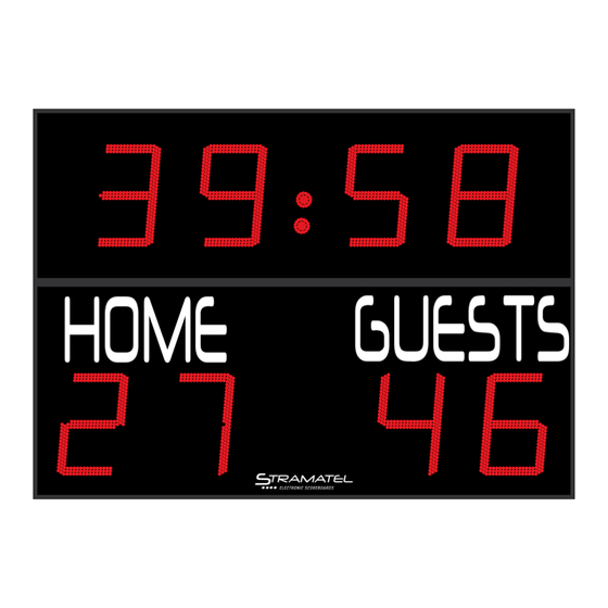
Summary of Contents for Stramatel FRC
- Page 1 Outdoor TECHNICAL DATA - INSTALLATION INSTRUCTIONS Model FRC Non-binding pictures ZI de Bel Air 44850 LE CELLIER FRANCE stramatel@stramatel.com Tél. +33 (0)2 40 25 46 90 IA452FRC-IM_D - Installation FRC.docx Page 1...
- Page 2 Outdoor NOTES ZI de Bel Air 44850 LE CELLIER FRANCE stramatel@stramatel.com Tél. +33 (0)2 40 25 46 90 IA452FRC-IM_D - Installation FRC.docx Page 2...
-
Page 3: Technical Data
Weight 650 g Power supply: the control console is powered by the scoreboard. It should only be connected to the STRAMATEL system supplied. Environment and recycling Please help us to protect the environment by disposing of the packaging in accordance with the national regulations for waste processing. - Page 4 Fix 2 clamps (D) on each fastening rail (G) as mentioned below. Tighten the screws (V), then unscrew them by quarter a turn (as a first step, the clamps should not be fully tightened). Dimensions en mm ZI de Bel Air 44850 LE CELLIER FRANCE stramatel@stramatel.com Tél. +33 (0)2 40 25 46 90 IA452FRC-IM_D - Installation FRC.docx Page 4...
- Page 5 Put the black plastic screws back into anchor points (I) of the module M2. Plug in the connectors (Y) between the modules. 2500 1500 ±250 180x90 ZI de Bel Air 44850 LE CELLIER FRANCE stramatel@stramatel.com Tél. +33 (0)2 40 25 46 90 IA452FRC-IM_D - Installation FRC.docx Page 5...
- Page 6 Fix the angle brackets with Ø8mm screws onto the wall or onto the support frame. 2598 2416 1702 1658 2000 Dimensions en mm ZI de Bel Air 44850 LE CELLIER FRANCE stramatel@stramatel.com Tél. +33 (0)2 40 25 46 90 IA452FRC-IM_D - Installation FRC.docx Page 6...
- Page 7 Put the black plastic screws back into anchor points (I) located on the top side of the module M2. Plug in the connectors (Y) between the modules and slide them into the back of the scoreboard. ZI de Bel Air 44850 LE CELLIER FRANCE stramatel@stramatel.com Tél. +33 (0)2 40 25 46 90 IA452FRC-IM_D - Installation FRC.docx Page 7...
- Page 8 (4) = +24V = transparent wire End of the installation Turn on the power. Try out the scoreboard operating functions (see operating functions). ZI de Bel Air 44850 LE CELLIER FRANCE stramatel@stramatel.com Tél. +33 (0)2 40 25 46 90 IA452FRC-IM_D - Installation FRC.docx Page 8...
- Page 9 Control cable (Q): (1) = GND = blue wire / (2) = Rx+ = white wire / (3) = Rx- = grey wire / (4) = +24V = transparent wire End of the installation Turn on the power. Try out the scoreboard operating functions (see operating functions). ZI de Bel Air 44850 LE CELLIER FRANCE stramatel@stramatel.com Tél. +33 (0)2 40 25 46 90 IA452FRC-IM_D - Installation FRC.docx Page 9...
- Page 10 ZI de Bel Air 44850 LE CELLIER FRANCE : +33 (0)2 40 25 46 90 Fax: +33 (0)2 40 25 30 63 stramatel@stramatel.com www.stramatel.com...


Need help?
Do you have a question about the FRC and is the answer not in the manual?
Questions and answers