Table of Contents
Advertisement
Advertisement
Table of Contents

Subscribe to Our Youtube Channel
Related Manuals for ASROCK X299 Steel Legend


Summary of Contents for ASROCK X299 Steel Legend
-
Page 2: Copyright Notice
(including damages for loss of profits, loss of business, loss of data, interruption of business and the like), even if ASRock has been advised of the possibility of such damages arising from any defect or error in the documentation or product. - Page 3 If you require assistance please call ASRock Tel : +886-2-28965588 ext.123 (Standard International call charges apply)
-
Page 4: Table Of Contents
Contents Chapter 1 Introduction Package Contents Specifications Motherboard Layout I/O Panel Chapter 2 Installation Installing the CPU Installing the CPU Fan and Heatsink Installation of Memory Modules (DIMM) Expansion Slots (PCI Express Slots) Jumpers Setup Onboard Headers and Connectors Smart Switch Post Status Checker and 3-Way SLI and Operation Guide... - Page 5 Chapter 3 Software and Utilities Operation Installing Drivers ASRock Motherboard Utility (A-Tuning) 3.2.1 Installing ASRock Motherboard Utility (A-Tuning) 3.2.2 Using ASRock Motherboard Utility (A-Tuning) ASRock Live Update & APP Shop 3.3.1 UI Overview 3.3.2 Apps 3.3.3 BIOS & Drivers 3.3.4...
- Page 6 4.6.4 Storage Configuration 4.6.5 Intel® Thunderbolt™ 4.6.7 ACPI Configuration 4.6.8 USB Configuration 4.6.9 Trusted Computing Tools Hardware Health Event Monitoring Screen Security Screen 4.10 Boot Screen 4.11 Exit Screen...
-
Page 7: Chapter 1 Introduction
If you require technical support related to this mother- board, please visit our website for specific information about the model you are using. You may find the latest VGA cards and CPU support list on ASRock’s website as well. ASRock website http://www.asrock.com. -
Page 8: Specifications
2666/2400/2133 non-ECC, un-buffered memory * The maximum memory frequency supported may vary by processor type. * Please refer to Memory Support List on ASRock’s website for more information. (http://www.asrock.com/) • Max. capacity of system memory: 256GB • Supports Intel® Extreme Memory Profile (XMP) 2.0 • 15μ... - Page 9 • 7.1 CH HD Audio with Content Protection (Realtek ALC1220 Audio Codec) • Premium Blu-ray Audio support • Supports Surge Protection (ASRock Full Spike Protection) • Supports Purity Sound - Nichicon Fine Gold Series Audio Caps - 120dB SNR DAC with Differential Amplifier...
- Page 10 • HD Audio Jacks: Rear Speaker / Central / Bass / Line in / Front Speaker / Microphone (Gold Audio Jacks) Storage • 8 x SATA3 6.0 Gb/s Connectors, support RAID (RAID 0, RAID 1, RAID 5, RAID 10, Intel Rapid Storage Technology 17 and Intel Smart Response Technology), NCQ, AHCI and Hot Plug* * If M2_1 is occupied by a SATA-type M.2 device, SATA3_1 will...
- Page 11 X299 Steel Legend * CPU_FAN2/WP, CHA_FAN1~5/WP can auto detect if 3-pin or 4-pin fan is in use. • 1 x 24 pin ATX Power Connector (Hi-Density Power Connector) • 2 x 8 pin 12V Power Connectors (Hi-Density Power Connector) • 1 x Front Panel Audio Connector (15μ Gold Audio Connector) • 1 x Thunderbolt AIC Connector (5-pin)
- Page 12 * For detailed product information, please visit our website: http://www.asrock.com Please realize that there is a certain risk involved with overclocking, including adjusting the setting in the BIOS, applying Untied Overclocking Technology, or using third-party overclocking tools. Overclocking may affect your system’s stability, or even cause damage to the components and devices of your system.
-
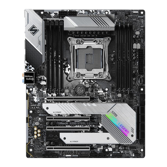
Page 13: Motherboard Layout
X299 Steel Legend 1.3 Motherboard Layout RGB_HEADER2 CPU_FAN2 CPU_FAN1 ATX12V1 ATX12V2 ADDR_LED2 DRAM BOOT CLRC BTN1 2066 Socket USB 2.0 Top: T: USB3 RJ-45 (I219V ) B: USB4 USB 3.2 Gen1 Top: T: USB1 RJ-45 I211AT B: USB2 USB 3.2 Gen1 T: USB3_3 USB 3.2 Gen2x2... - Page 14 No. Description 2 x 288-pin DDR4 DIMM Slots (DDR4_A1, DDR4_B1) 2 x 288-pin DDR4 DIMM Slots (DDR4_A2, DDR4_B2) ATX 12V Power Connector (ATX12V1) ATX 12V Power Connector (ATX12V2) CPU Fan Connector (CPU_FAN1) 2 x 288-pin DDR4 DIMM Slots (DDR4_C2, DDR4_D2) 2 x 288-pin DDR4 DIMM Slots (DDR4_C1, DDR4_D1) CPU / Waterpump Fan Connector (CPU_FAN2/WP) RGB LED Header (RGB_HEADER2)
-
Page 15: I/O Panel
X299 Steel Legend 1.4 I/O Panel No. Description Description USB 2.0 Port (USB_12) USB 3.2 Gen1 Port (USB3_3) LAN RJ-45 Port (Intel® I219V)* USB 3.2 Gen2x2 Type-C Port LAN RJ-45 Port (Intel® I211AT)* (USB31_TC_1) Central / Bass (Orange) USB 3.2 Gen1 Ports (USB3_12) Rear Speaker (Black) USB 2.0 Port (USB_34) - Page 16 **If you use a 2-channel speaker, please connect the speaker’s plug into “Front Speaker Jack”. See the table below for connection details in accordance with the type of speaker you use. Audio Output Front Speaker Rear Speaker Central / Bass Line In Channels (No.
-
Page 17: Chapter 2 Installation
X299 Steel Legend Chapter 2 Installation This is an ATX form factor motherboard. Before you install the motherboard, study the configuration of your chassis to ensure that the motherboard fits into it. Pre-installation Precautions Take note of the following precautions before you install motherboard components or change any motherboard settings. -
Page 18: Installing The Cpu
2.1 Installing the CPU 1. Before you insert the 2066-Pin CPU into the socket, please check if the PnP cap is on the socket, if the CPU surface is unclean, or if there are any bent pins in the socket. Do not force to insert the CPU into the socket if above situation is found. - Page 19 X299 Steel Legend...
- Page 20 Please save and replace the cover if the processor is removed. The cover must be placed if you wish to return the motherboard for after service.
-
Page 21: Installing The Cpu Fan And Heatsink
X299 Steel Legend 2.2 Installing the CPU Fan and Heatsink... -
Page 22: Installation Of Memory Modules (Dimm)
2.3 Installation of Memory Modules (DIMM) This motherboard provides eight 288-pin DDR4 (Double Data Rate 4) DIMM slots, and supports Quad Channel Memory Technology. 1. For quad channel configuration, you always need to install identical (the same brand, speed, size and chip-type) DDR4 DIMM pairs. 2. - Page 23 X299 Steel Legend...
-
Page 24: Expansion Slots (Pci Express Slots)
2.4 Expansion Slots (PCI Express Slots) There are 5 PCI Express slots on the motherboard. Before installing an expansion card, please make sure that the power supply is switched off or the power cord is unplugged. Please read the documentation of the expansion card and make necessary hardware settings for the card before you start the installation. - Page 25 X299 Steel Legend PCIe Slot Configurations (For CPU with 44 PCIe lanes) PCIE1 PCIE2 PCIE3 PCIE5 Single Graphics Card Two Graphics Cards in CrossFireX or SLI Mode Three Graphics Cards in 3-Way CrossFireX Mode or 3-Way SLI Mode PCIe Slot Configurations (For CPU with 28 PCIe lanes)
-
Page 26: Jumpers Setup
2.5 Jumpers Setup The illustration shows how jumpers are setup. When the jumper cap is placed on the pins, the jumper is “Short”. If no jumper cap is placed on the pins, the jumper is “Open”. The illustration shows a 3-pin jumper whose pin1 and pin2 are “Short” when a jumper cap is placed on these 2 pins. -
Page 27: Onboard Headers And Connectors
X299 Steel Legend 2.6 Onboard Headers and Connectors Onboard headers and connectors are NOT jumpers. Do NOT place jumper caps over these headers and connectors. Placing jumper caps over the headers and connectors will cause permanent damage to the motherboard. - Page 28 Power LED and Speaker Please connect the SPEAKER DUMMY Header chassis power LED and DUMMY (7-pin SPK_PLED1) the chassis speaker to this (see p.7, No. 22) header. PLED+ PLED+ PLED- Serial ATA3 Connectors These eight SATA3 (SATA3_0_1: connectors support SATA see p.7, No.
- Page 29 X299 Steel Legend USB 3.2 Gen1 Header There is one header on Dummy IntA_PA_D+ IntA_PB_D+ IntA_PA_D- (19-pin USB3_4_5) this motherboard. This IntA_PB_D- IntA_PA_SSTX+ (see p.7, No. 15) USB 3.2 Gen1 header can IntA_PB_SSTX+ IntA_PA_SSTX- IntA_PB_SSTX- support two ports. IntA_PA_SSRX+ IntA_PB_SSRX+...
- Page 30 Chassis Water Pump Fan This motherboard Connectors provides five 4-Pin water (4-pin CHA_FAN1/WP) cooling chassis fan FAN_VOLTAGE (see p.7, No. 34) connectors. If you plan to CHA_FAN_SPEED FAN_SPEED_CONTROL (4-pin CHA_FAN2/WP) connect a 3-Pin chassis (see p.7, No. 20) water cooler fan, please connect it to Pin 1-3.
- Page 31 X299 Steel Legend ATX 12V Power This motherboard Connectors provides two 8-pin ATX (8-pin ATX12V1) 12V power connectors. To (see p.7, No. 3) use a 4-pin ATX power (8-pin ATX12V2) supply, please plug it along (see p.7, No. 4) Pin 1 and Pin 5.
- Page 32 RGB LED Headers These two RGB headers are used (4-pin RGB_HEADER1) to connect RGB LED 12V G R (see p.7, No. 30) extension cable which allows (4-pin RGB_HEADER2) users to choose from various LED (see p.7, No. 9) lighting effects. Caution: Never install the RGB LED cable in the wrong orienta- tion;...
- Page 33 X299 Steel Legend Virtual RAID On CPU This connector supports Intel® Header Virtual RAID on CPU and (4-pin VROC1) NVME/AHCI RAID on CPU +3VSB (see p.7, No. 14) PCIE. VROC RAID KEY With the introduction of the Intel VROC product, there are three modes of operation:...
-
Page 34: Smart Switch
2.7 Smart Switch The motherboard has a smart switch: Clear CMOS Button, allowing users to quickly clear the CMOS values. Clear CMOS Button Clear CMOS Button (CLRCBTN1) allows users to quickly (see p.9, No. 14) clear the CMOS values. This function is workable only when you power off your computer and unplug the power supply. -
Page 35: Post Status Checker
X299 Steel Legend 2.8 Post Status Checker Post Status Checker (PSC) diagnoses the computer when users power on the machine. It emits a red light to indicate whether the CPU, memory, VGA or stor- age is dysfunctional. The lights go off if the four mentioned above are functioning... -
Page 36: Sli Tm And 3-Way Sli Tm And Operation Guide
2.9 SLI and 3-Way SLI and Operation Guide ® This motherboard supports NVIDIA and 3-Way SLI (Scalable Link Interface) technology that allows you to install up to three identical PCI Express x16 ® graphics cards. Currently, NVIDIA technology supports Windows® 10 64-bit * 3-Way CrossFireX is only supported with CPU with 48 lanes or 44 lanes. - Page 37 X299 Steel Legend Step 3 Align and insert the ASRock SLI_HB_ Bridge_2S Card to the goldfingers on each graphics card. Make sure the ASRock SLI_ HB_Bridge_2S Card is firmly in place. SLI_HB_Bridge_2S Car d ASRock SLI_HB_Bridge_2S Card Step 4 Connect a VGA cable or a DVI cable to the...
-
Page 38: Installing Three Sli Tm -Ready Graphics Cards
2.9.2 Installing Three SLI -Ready Graphics Cards Step 1 Insert one graphics card into PCIE1 slot, another graphics card to PCIE3 slot, and the other graphics card to PCIE5 slot. Make sure that the cards are properly seated on the slots. Step 2 Connect the auxiliary power source to the PCI Express graphics card. - Page 39 X299 Steel Legend Step 4 Connect a VGA cable or a DVI cable to the monitor connector or the DVI connector of the graphics card that is inserted to PCIE1 slot.
-
Page 40: Driver Installation And Setup
2.9.3 Driver Installation and Setup Install the graphics card drivers to your system. After that, you can enable the ® Multi-Graphics Processing Unit (GPU) in the NVIDIA nView system tray utility. Please follow the below procedures to enable the multi-GPU. Step 1 Double-click the NVIDIA Control Panel ®... -
Page 41: Crossfirex Tm And 3-Way Crossfirex Tm Operation Guide
X299 Steel Legend 2.10 CrossFireX and 3-Way CrossFireX Operation Guide This motherboard supports CrossFireX and 3-way CrossFireX that allows you to install up to three identical PCI Express x16 graphics cards. Currently CrossFireX and 3-way CrossFireX are supported with Windows® 10 64-bit OS. - Page 42 Step 3 Connect a VGA cable or a DVI cable to the monitor connector or the DVI connector of the graphics card that is inserted to PCIE1 slot.
-
Page 43: Installing Three Crossfirex
X299 Steel Legend 2.10.2 Installing Three CrossFireX -Ready Graphics Cards Step 1 Insert one graphics card into PCIE1 slot, another graphics card to PCIE3 slot, and the other graphics card to PCIE5 slot. Make sure that the cards are properly seated on the slots. -
Page 44: Driver Installation And Setup
2.10.3 Driver Installation and Setup Step 1 Power on your computer and boot into OS. Step 2 Remove the AMD drivers if you have any VGA drivers installed in your system. The Catalyst Uninstaller is an optional download. We recommend using this utility to un- install any previously installed Catalyst drivers prior to installation. - Page 45 X299 Steel Legend 2.14 M.2_SSD (NGFF) Module Installation Guide (M2_1) The M.2, also known as the Next Generation Form Factor (NGFF), is a small size and versatile card edge connector that aims to replace mPCIe and mSATA. The Ultra M.2 Socket can accommodate either a M.2 SATA3 6.0 Gb/s module or a M.2 PCI Express...
- Page 46 Step 3 Before installing a M.2 (NGFF) SSD module, please loosen the screws to remove the M.2 heatsink. Step 4 Prepare the M.2 standoff that comes with the package. Then hand tighten the standoff into the desired nut location on the motherboard. Align and gently insert the M.2 (NGFF) SSD module into the M.2 slot.
- Page 47 X299 Steel Legend M.2_SSD (NGFF) Module Support List Vendor Interface ADATA SATA3 AXNS330E-32GM-B ADATA SATA3 AXNS381E-128GM-B ADATA SATA3 AXNS381E-256GM-B ADATA SATA3 ASU800NS38-256GT-C ADATA SATA3 ASU800NS38-512GT-C ADATA PCIe3 x4 ASX8000NP-256GM-C ADATA PCIe3 x4 ASX8000NP-512GM-C Crucial SATA3 CT120M500SSD4 Crucial SATA3 CT240M500SSD4 Intel...
- Page 48 SATA3 WDS100T1B0B-00AS40 SATA3 WDS240G1G0B-00RC30 PCIe3 x4 WDS256G1X0C-00ENX0 (NVME) PCIe3 x4 WDS512G1X0C-00ENX0 (NVME) For the latest updates of M.2_SSD (NFGG) module support list, please visit our website for details: http://www.asrock.com...
-
Page 49: 2_Ssd (Ngff) Module Installation Guide (M2
X299 Steel Legend 2.12 M.2_SSD (NGFF) Module Installation Guide (M2_2) The M.2, also known as the Next Generation Form Factor (NGFF), is a small size and versatile card edge connector that aims to replace mPCIe and mSATA. The Ultra M.2 Socket can accommodate either a M.2 SATA3 6.0 Gb/s module or a M.2 PCI Express... - Page 50 Step 3 Before installing a M.2 (NGFF) SSD module, please loosen the screws to remove the M.2 heatsink. *Please remove the protective films on the bottom side of the M.2 heatsink before you install a M.2 SSD module. Step 4 Prepare the M.2 standoff that comes with the package.
- Page 51 X299 Steel Legend M.2_SSD (NGFF) Module Support List Vendor Interface ADATA SATA3 AXNS381E-128GM-B ADATA SATA3 AXNS381E-256GM-B ADATA SATA3 ASU800NS38-256GT-C ADATA SATA3 ASU800NS38-512GT-C ADATA PCIe3 x4 ASX7000NP-128GT-C ADATA PCIe3 x4 ASX8000NP-256GM-C ADATA PCIe3 x4 ASX7000NP-256GT-C ADATA PCIe3 x4 ASX8000NP-512GM-C ADATA PCIe3 x4...
- Page 52 SATA3 VLM100-120G-2280B-RD V-Color SATA3 VLM100-240G-2280RGB V-Color SATA3 VSM100-240G-2280 V-Color SATA3 VLM100-240G-2280B-RD SATA3 WDS100T1B0B-00AS40 SATA3 WDS240G1G0B-00RC30 PCIe3 x4 WDS256G1X0C-00ENX0 (NVME) PCIe3 x4 WDS512G1X0C-00ENX0 (NVME) For the latest updates of M.2_SSD (NFGG) module support list, please visit our website for details: http://www.asrock.com...
-
Page 53: Chapter 3 Software And Utilities Operation
X299 Steel Legend Chapter 3 Software and Utilities Operation 3.1 Installing Drivers The Support CD that comes with the motherboard contains necessary drivers and useful utilities that enhance the motherboard’s features. Running The Support CD To begin using the support CD, insert the CD into your CD-ROM drive. The CD automatically displays the Main Menu if “AUTORUN”... -
Page 54: Asrock Motherboard Utility (A-Tuning)
3.2.1 Installing ASRock Motherboard Utility (A-Tuning) ASRock Motherboard Utility (A-Tuning) can be downloaded from ASRock Live Update & APP Shop. After the installation, you will find the icon “ASRock Mother- board Utility (A-Tuning)“ on your desktop. Double-click the “ASRock Motherboard Utility (A-Tuning)“... - Page 55 X299 Steel Legend OC Tweaker Configurations for overclocking the system. System Info View information about the system. *The System Browser tab may not appear for certain models.
- Page 56 Settings Configure ASRock ASRock Motherboard Utility (A-Tuning). Click to select "Auto run at Windows Startup" if you want ASRock Motherboard Utility (A-Tuning) to be launched when you start up the Windows operating system.
-
Page 57: Asrock Live Update & App Shop
Double-click on your desktop to access ASRock Live Update & APP Shop utility. *You need to be connected to the Internet to download apps from the ASRock Live Update & APP Shop. 3.3.1 UI Overview Category Panel Hot News... -
Page 58: Apps
3.3.2 Apps When the "Apps" tab is selected, you will see all the available apps on screen for you to download. Installing an App Step 1 Find the app you want to install. The most recommended app appears on the left side of the screen. The other various apps are shown on the right. - Page 59 X299 Steel Legend Step 3 If you want to install the app, click on the red icon to start downloading. Step 4 When installation completes, you can find the green "Installed" icon appears on the upper right corner. To uninstall it, simply click on the trash can icon...
- Page 60 Upgrading an App You can only upgrade the apps you have already installed. When there is an available new version for your app, you will find the mark of "New Version" appears below the installed app icon. Step 1 Click on the app icon to see more details. Step 2 Click on the yellow icon to start upgrading.
-
Page 61: Bios & Drivers
X299 Steel Legend 3.3.3 BIOS & Drivers Installing BIOS or Drivers When the "BIOS & Drivers" tab is selected, you will see a list of recommended or critical updates for the BIOS or drivers. Please update them all soon. Step 1 Please check the item information before update. -
Page 62: Setting
3.3.4 Setting In the "Setting" page, you can change the language, select the server location, and determine if you want to automatically run the ASRock Live Update & APP Shop on Windows startup. -
Page 63: Asrock Polychrome Sync
X299 Steel Legend 3.4 ASRock Polychrome SYNC ASRock Polychrome SYNC is a lighting control utility specifically designed for unique indi- viduals with sophisticated tastes to build their own stylish colorful lighting system. Simply by connecting the LED strip, you can customize various lighting schemes and patterns, including Static, Breathing, Strobe, Cycling, Music, Wave and more. - Page 64 Connecting the Addressable RGB LED Strip Connect your Addressable RGB LED strip to the Addressable LED Header (ADDR_LED1, ADDR_LED2 ) on the motherboard. ADDR_LED2 DO_ADDR VOUT ADDR_LED1 DO_ADDR VOUT 1. Never install the RGB LED cable in the wrong orientation; otherwise, the cable may be damaged.
- Page 65 ASRock Polychrome SYNC Utility Now you can adjust the RGB LED color through the ASRock Polychrome SYNC Utility. Download this utility from the ASRock Live Update & APP Shop and start coloring your PC style your way! Drag the tab to customize your preference.
-
Page 66: Chapter 4 Uefi Setup Utility
Chapter 4 UEFI SETUP UTILITY 4.1 Introduction This section explains how to use the UEFI SETUP UTILITY to configure your system. You may run the UEFI SETUP UTILITY by pressing <F2> or <Del> right after you power on the computer, otherwise, the Power-On-Self-Test (POST) will continue with its test routines. -
Page 67: Ez Mode
X299 Steel Legend 4.2 EZ Mode The EZ Mode screen appears when you enter the BIOS setup program by default. EZ mode is a dashboard which contains multiple readings of the system’s current status. You can check the most crucial information of your system, such as CPU speed, DRAM frequency, SATA information, fan speed, etc. -
Page 68: Advanced Mode
4.3 Advanced Mode The Advanced Mode provides more options to configure the BIOS settings. Refer to the following sections for the detailed configurations. To access the EZ Mode, press <F6> or click the "EZ Mode" button at the upper right corner of the screen. -
Page 69: Navigation Keys
X299 Steel Legend 4.3.2 Navigation Keys Use < > key or < > key to choose among the selections on the menu bar, and use < > key or < > key to move the cursor up or down to select items, then press <Enter>... -
Page 70: Main Screen
4.4 Main Screen When you enter the UEFI SETUP UTILITY, the Main screen will appear and display the system overview. Favorite Display your collection of BIOS items. Press F5 to add/remove your favorite items. -
Page 71: Oc Tweaker Screen
X299 Steel Legend 4.5 OC Tweaker Screen In the OC Tweaker screen, you can set up overclocking features. Because the UEFI software is constantly being updated, the following UEFI setup screens and descriptions are for reference purpose only, and they may not exactly match what you... -
Page 72: Cpu Configuration
Load Optimized CPU OC Setting You can use this option to load optimized CPU overclocking setting. Please note that overclocking may cause damage to your CPU and motherboard. It should be done at your own risk and expense. CPU Configuration Multi Core Enhancement Improve the system’s performance by forcing the CPU to perform the highest fre- quency on all CPU cores simultaneously. -
Page 73: Boot Performance Mode
X299 Steel Legend Intel Turbo Boost Max Technology 3.0 Intel Turbo Boost Technology 3.0 enables the processor to run above its base operating frequency when the operating system requests the highest performance state. Adjust Pll Adjust the Pll for higher -BCLK ration combination. -
Page 74: Long Duration Maintained
Primary Plane Current Limit Configure the current limit of the CPU under Turbo Mode in ampere. A lower limit can protect the CPU and save power, while a higher limit may improve performance. Long Duration Power Limit Configure Package Power Limit 1 in watts. When the limit is exceeded, the CPU ratio will be lowered after a period of time. - Page 75 X299 Steel Legend Primary Timing CAS# Latency (tCL) The time between sending a column address to the memory and the beginning of the data in response. RAS# to CAS# Delay and Row Precharge (tRCDtRP) RAS# to CAS# Delay : The number of clock cycles required between the opening of a row of memory and accessing columns within it.
- Page 76 Write to Read Delay (tWTR) The number of clocks between the last valid write operation and the next read command to the same internal bank. Write to Read Delay (tWTR_L) The number of clocks between the last valid write operation and the next read command to the same internal bank.
- Page 77 X299 Steel Legend tCCD_WR_L Configure back to back CAS to CAS (i.e. READ to RAED or WRITE to WRITE) from same rank separation parameter. Turn Around Timimg tRRDS The number of clocks between two rows activated in different banks of the same rank.
- Page 78 tWWDS Use this item to change tWWDS setting. The default is [Auto]. tWWDS_L Use this item to change tWWDS_L setting. The default is [Auto]. tWWDR Use this item to change tWWDR setting. The default is [Auto] tWWDD Use this item to change tWWDD setting. The default is [Auto] Round Trip Timing RTL (A1) Configure round trip latency for channel A1.
- Page 79 X299 Steel Legend IOL (A2) Configure IO latency for channel A2. IOL (B1) Configure IO latency for channel B1. IOL (B2) Configure IO latency for channel B2. IOL (C1) Configure IO latency for channel B1. IOL (C2) Configure IO latency for channel B2.
- Page 80 ODT WR (D1) Configure the memory on die termination resistors' WR for channel D1. ODT WR (D2) Configure the memory on die termination resistors' WR for channel D2. ODT PARK (A1) Configure the memory on die termination resistors' PARK for channel A1. ODT PARK (A2) Configure the memory on die termination resistors' PARK for channel A2.
-
Page 81: Advanced Setting
X299 Steel Legend ODT NOM (C1) Use this to change ODT (CH C1) Auto/Manual settings. The default is [Auto]. ODT NOM (C2) Use this to change ODT (CH C2) Auto/Manual settings. The default is [Auto]. ODT NOM (D1) Use this to change ODT (CH D 1) Auto/Manual settings. The default is [Auto]. -
Page 82: Voltage Configuration
Voltage Configuration CPU Input Voltage Configure the voltage for the CPU Vcore. CPU Load-Line Calibration CPU Load-Line Calibration helps prevent CPU voltage droop when the system is under heavy loading. VPPM AB Voltage Configure the voltage for the VPPM AB. DRAM AB Voltage Configure the voltage for the DRAM AB. - Page 83 X299 Steel Legend Vcore Voltage Offset Configure the dynamic Vcore voltage added to the Vcore. Offset Prefix Sets the offset value as positive or negative. CPU Mesh Voltage Offset Configure the amount of voltage fed to the UNCores of the processor, including its cache.
- Page 84 Dynamic SVID Support Enable/Disable SVID. Disabling SVID disables input voltage overrides. Save User Default Type a profile name and press enter to save your settings as user default. Load User Default Load previously saved user defaults. Save User UEFI Setup Profile to Disk It helps you to save current UEFI settings as an user profile to disk Load User UEFI Setup Profile from Disk You can load previous saved profile from the disk...
-
Page 85: Advanced Screen
X299 Steel Legend 4.6 Advanced Screen In this section, you may set the configurations for the following items: CPU Configuration, IIO Configuration, Chipset Configuration, Storage Configuration, Intel® Thunderbolt, Super IO Configuration, ACPI Configuration, USB Configura- tion and Trusted Computing. Setting wrong values in this section may cause the system to malfunction. -
Page 86: Cpu Configuration
4.6.1 CPU Configuration Intel Hyper Threading Technology Intel Hyper Threading Technology allows multiple threads to run on each core, so that the overall performance on threaded software is improved. Active CB0 Cores Use this item to configure the active CB0 Cores (Physical Core). CPU C States Support Enable CPU C States Support for power saving. -
Page 87: Hardware Prefetcher
X299 Steel Legend and applications in independent partitions, so that one computer system can function as multiple virtual systems. Intel Safer Mode Extensions (SMX) Enable/disable the Intel SMX (Safer Mode Extensions). Hardware Prefetcher Automatically prefetch data and code for the processor. Enable for better performance. -
Page 88: Iio Configuration
4.6.2 IIO Configuration IOU0 (PCIE3) Select PCIe port Bifurcation for selected slot(s). Configuration options: [x4x4x4x4], [x4x4x8], [x8x4x4], [x8x8], [x16], [Auto] IOU1 (PCIE1) Select PCIe port Bifurcation for selected slot(s). Configuration options: [x4x4x4x4], [x4x4x8], [x8x4x4], [x8x8], [x16], [Auto]... -
Page 89: Chipset Configuration
X299 Steel Legend 4.6.3 Chipset Configuration Above 4GB MMIO BIOS Assignment Enable/disable above 4GB MemoryMappedIO BIOS assignment. This is disabled automatically when Aperture Size is set to 2048MB. VT-d Intel® Virtualization Technology for Directed I/O helps your virtual machine monitor better utilize hardware by improving application compatibility and reliability, and providing additional levels of manageability, security, isolation, and I/O performance. -
Page 90: Onboard Lan
PCIE3 Link Speed Select the link speed for PCIE3. PCIE4 Link Speed Select the link speed for PCIE4. PCIE5 Link Speed Select the link speed for PCIE5. PCIE ASPM Support This option enables/disables the ASPM support for all CPU downstream devices. PCH PCIE ASPM Support This option enables/disables the ASPM support for all PCH PCIE devices. - Page 91 X299 Steel Legend Deep Sleep Configure deep sleep mode for power saving when the computer is shut down. Restore on AC/Power Loss Select the power state after a power failure. If [Power Off] is selected, the power will remain off when the power recovers. If [Power On] is selected, the system will start to boot up when the power recovers.
-
Page 92: Storage Configuration
4.6.4 Storage Configuration SATA Controller(s) Enable/disable the SATA controllers. SATA Controller Speed Indicates the maximum speed the SATA controller can support. SATA Mode Selection [AHCI]: Supports new features that improve performance. [RAID]: Combine multiple disk drives into a logical unit. SATA Aggressive Link Power Management SATA Aggressive Link Power Management allows SATA devices to enter a low power state during periods of inactivity to save power. - Page 93 X299 Steel Legend Intel VMD Technology Use this option to configure the Intel VMD (Volume management Device) Technology. VROC AIC: Supports up to four M.2 devices on VROC AIC.
-
Page 94: Intel® Thunderbolt
4.6.5 Intel® Thunderbolt™ Intel(R) Thunderbolt Technonogy Enable/Disable the Intel(R) Thunderbolt function. Security Level Allows you to choose a security level for the Thunderbolt ports... -
Page 95: Super Io Configuration
X299 Steel Legend 4.6.6 Super IO Configuration PS2 Y-Cable Enable the PS2 Y-Cable or set this option to Auto. -
Page 96: Acpi Configuration
4.6.7 ACPI Configuration Suspend to RAM Select disable for ACPI suspend type S1. It is recommended to select auto for ACPI S3 power saving. PS/2 Keyboard S4/S5 Wakeup Support Allow the system to be waked up by a PS/2 Keyboard in S4/S5. PCIE Devices Power On Allow the system to be waked up by a PCIE device and enable wake on LAN. -
Page 97: Usb Configuration
X299 Steel Legend 4.6.8 USB Configuration Legacy USB Support Enable or disable Legacy OS Support for USB 2.0 devices. If you encounter USB compatibility issues it is recommended to disable legacy USB support. Select UEFI Setup Only to support USB devices under the UEFI setup and Windows/Linux operating systems only. -
Page 98: Trusted Computing
4.6.9 Trusted Computing Security Device Support Enable or disable BIOS support for security device. -
Page 99: Tools
X299 Steel Legend 4.7 Tools UEFI Tech Service Contact ASRock Tech Service if you are having trouble with your PC. Please setup network configuration before using UEFI Tech Service. Easy RAID Installer Easy RAID Installer helps you to copy the RAID driver from the support CD to your USB storage device. -
Page 100: Network Configuration
*For BIOS backup and recovery purpose, it is recommended to plug in your USB pen drive before using this function. Network Configuration Use this to configure internet connection settings for Internet Flash. Internet Setting Enable or disable sound effects in the setup utility. UEFI Download Server Select a server to download the UEFI firmware. -
Page 101: Hardware Health Event Monitoring Screen
X299 Steel Legend 4.8 Hardware Health Event Monitoring Screen This section allows you to monitor the status of the hardware on your system, including the parameters of the CPU temperature, motherboard temperature, fan speed and voltage. Fan Tuning Measure Fan Min Duty Cycle. - Page 102 CPU_FAN2 / W_Pump Switch Select CPU Water Pump mode. CPU Fan 2 Control Mode Select PWM mode or DC mode for CPU Fan 2. CPU Fan 2 Setting Select a fan mode for CPU Fan 2, or choose Customize to set 5 CPU temperatures and assign a respective fan speed for each temperature.
- Page 103 X299 Steel Legend Chassis Fan 2 Control Mode Select PWM mode or DC mode for Chassis Fan 2. Chassis Fan 2 Setting Select a fan mode for Chassis Fan 2, or choose Customize to set 5 CPU temperatures and assign a respective fan speed for each temperature.
- Page 104 Chassis Fan 4 Setting Select a fan mode for Chassis Fan 4, or choose Customize to set 5 CPU temperatures and assign a respective fan speed for each temperature. Chassis Fan 4 Temp Source Select a fan temperature source for Chassis Fan 4. Chassis Fan 4 Step Up Set the value of Chassis Fan 4 Step Up.
-
Page 105: Security Screen
X299 Steel Legend 4.9 Security Screen In this section you may set or change the supervisor/user password for the system. You may also clear the user password. Supervisor Password Set or change the password for the administrator account. Only the administrator has authority to change the settings in the UEFI Setup Utility. -
Page 106: Boot Screen
4.10 Boot Screen This section displays the available devices on your system for you to configure the boot settings and the boot priority. Fast Boot Fast Boot minimizes your computer's boot time. In fast mode you may not boot from an USB storage device. - Page 107 X299 Steel Legend Full Screen Logo Enable to display the boot logo or disable to show normal POST messages. AddOn ROM Display Enable AddOn ROM Display to see the AddOn ROM messages or configure the AddOn ROM if you've enabled Full Screen Logo. Disable for faster boot speed.
- Page 108 Launch Storage OpROM Policy Select UEFI only to run those that support UEFI option ROM only. Select Legacy only to run those that support legacy option ROM only. Select Do not launch to not execute both legacy and UEFI option ROM. Other PCI Device ROM Priority For PCI devices other than Network.
-
Page 109: Exit Screen
X299 Steel Legend 4.11 Exit Screen Save Changes and Exit When you select this option the following message, “Save configuration changes and exit setup?” will pop out. Select [OK] to save changes and exit the UEFI SETUP UTILITY. Discard Changes and Exit When you select this option the following message, “Discard changes and exit... -
Page 110: Contact Information
Contact Information If you need to contact ASRock or want to know more about ASRock, you’re welcome to visit ASRock’s website at http://www.asrock.com; or you may contact your dealer for further information. For technical questions, please submit a support request form at https://event.asrock.com/tsd.asp... -
Page 111: Declaration Of Conformity
13848 Magnolia Ave, Chino, CA91710 Phone/Fax No: +1-909-590-8308/+1-909-590-1026 hereby declares that the product Product Name : Motherboard X299 Steel Legend Model Number : Conforms to the following speci cations: FCC Part 15, Subpart B, Unintentional Radiators Supplementary Information: is device complies with part 15 of the FCC Rules. Operation is subject to the... - Page 112 EU Declaration of Conformity For the following equipment: Motherboard (Product Name) X299 Steel Legend/ ASRock (Model Designation / Trade Name) ASRock Incorporation (Manufacturer Name) 2F., No.37, Sec. 2, Jhongyang S. Rd., Beitou District, Taipei City 112, Taiwan (R.O.C.) (Manufacturer Address) EMC —Directive 2014/30/EU (from April 20th, 2016)
Need help?
Do you have a question about the X299 Steel Legend and is the answer not in the manual?
Questions and answers