Table of Contents
Advertisement
Advertisement
Table of Contents

Related Manuals for ASROCK X299E-ITX/ac


Summary of Contents for ASROCK X299E-ITX/ac
-
Page 2: Copyright Notice
(including damages for loss of profits, loss of business, loss of data, interruption of business and the like), even if ASRock has been advised of the possibility of such damages arising from any defect or error in the documentation or product. - Page 3 If you require assistance please call ASRock Tel : +886-2-28965588 ext.123 (Standard International call charges apply) Manufactured under license under U.S.
-
Page 4: Table Of Contents
Onboard Headers and Connectors Smart Switches M.2_SSD (NGFF) Module Installation Guide (M2_1) M.2_SSD (NGFF) Module Installation Guide (M2_2 and M2_3) 31 Chapter 3 Software and Utilities Operation Installing Drivers A-Tuning 3.2.1 Installing A-Tuning 3.2.2 Using A-Tuning ASRock Live Update & APP Shop... - Page 5 3.3.1 UI Overview 3.3.2 Apps 3.3.3 BIOS & Drivers 3.3.4 Setting ASRock RGB LED Chapter 4 UEFI SETUP UTILITY Introduction EZ Mode Advanced Mode 4.3.1 UEFI Menu Bar 4.3.2 Navigation Keys Main Screen OC Tweaker Screen Advanced Screen 4.6.1 CPU Configuration 4.6.2 Chipset Configuration...
- Page 6 4.11 Exit Screen...
-
Page 7: Chapter 1 Introduction
ASRock’s website without further notice. If you require technical support related to this motherboard, please visit our website for specific information about the model you are using. You may find the latest VGA cards and CPU support list on ASRock’s website as well. ASRock website http://www.asrock.com. -
Page 8: Specifications
78xx Series) for the LGA 2066 Socket * Supports 28 and 44 PCIe lane processors (6-core and above) only. 16 PCIe lane processors (4-core) are not supported. Please refer to CPU Support List on ASRock’s website for more infor- mation. (http://www.asrock.com/) • Digi Power design • 7 Power Phase design... - Page 9 X299E-ITX/ac • Supports Purity Sound - Nichicon Fine Gold Series Audio Caps - 120dB SNR DAC with Differential Amplifier - NE5532 Premium Headset Amplifier for Front Panel Audio Connector (Supports up to 600 Ohm headsets) - Pure Power-In - Direct Drive Technology...
- Page 10 • 1 x Clear CMOS Button / Power Button • HD Audio Jacks: Rear Speaker / Central / Bass / Line in / Front Speaker / Microphone (Gold Audio Jacks) Storage • 6 x SATA3 6.0 Gb/s Connectors, support RAID (RAID 0, RAID 1, RAID 5, RAID 10, Intel Rapid Storage Technology 15 and Intel Smart Response Technology), NCQ, AHCI and Hot Plug*...
- Page 11 • ErP/EuP ready (ErP/EuP ready power supply is required) * For detailed product information, please visit our website: http://www.asrock.com Please realize that there is a certain risk involved with overclocking, including adjusting the setting in the BIOS, applying Untied Overclocking Technology, or using third-party overclocking tools.
-
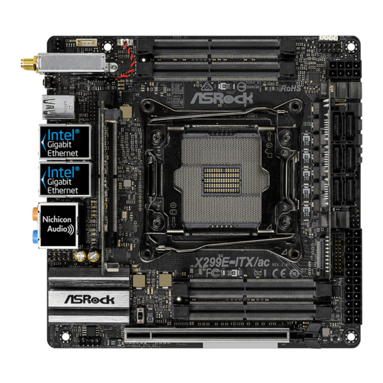
Page 12: Motherboard Layout
B: USB31_TC_1 USB 3.1 Gen1 Top: T: USB1 LAN1 B: USB2 USB 3.1 Gen1 Top: T: USB3 LAN2 B: USB4 CPU_FAN1 CPU_OPT/W_PUMP SPK_PLED1 X299E-ITX/ac HD_AUDIO1 Intel DDR4_D1 (64 bit, 260-pin module) FSB800 X299 REAR_BTN_SEL1 DDR4_C1 (64 bit, 260-pin module) FSB800 PCIE1... - Page 13 X299E-ITX/ac Back Side View...
- Page 14 Rear Card (For Rear Socket) X299E-ITX REAR CT14 CT13 CT12 CT11 RoHS Front Card (For Front Socket) USB_7_8 USB_5_6 SATA3_6_7 SATA3_4_5 SATA3_2_3 X299E-ITX FRONT RoHS...
- Page 15 X299E-ITX/ac No. Description Chassis Fan / Waterpump Fan Connector (CHA_FAN1/W_PUMP) Virtual RAID On CPU Header (VROC1) 2 x 260-pin DDR4 SO-DIMM Slots (DDR4_A1, DDR4_B1) RGB LED Header (RGB_LED1) System Panel Header (PANEL1) ATX 12V Power Connector (ATX12V1) Front Socket (FRONTI_IO1)
-
Page 16: I/O Panel
1.4 I/O Panel No. Description No. Description USB 3.1 Gen2 Type-A Port (USB31_TA_1) Microphone (Pink) LAN RJ-45 Port (Intel® I211AT)* Optical SPDIF Out Port LAN RJ-45 Port (Intel® I219V)* USB 3.1 Gen1 Ports (USB_34) Central / Bass (Orange) USB 3.1 Gen1 Ports (USB_12) Rear Speaker (Black) USB 3.1 Gen2 Type-C Port (USB31_TC_1) Line In (Light Blue) - Page 17 X299E-ITX/ac ** If you use a 2-channel speaker, please connect the speaker’s plug into “Front Speaker Jack”. See the table below for connection details in accordance with the type of speaker you use. Audio Output Front Speaker Rear Speaker Central / Bass...
-
Page 18: Intel® Dual Band Wireless-Ac 8265 (Ac Wave 2 + Ble Bt4.2) And Asrock Wifi 2.4/5 Ghz Antenna
1.5 Intel® Dual Band Wireless-AC 8265 (AC Wave 2 + BLE BT4.2) and ASRock WiFi 2.4/5 GHz Antenna WiFi-802.11ac + BT Module This motherboard comes with an exclusive WiFi 802.11 a/b/g/n/ac + BT v4.2 module (pre-installed on the rear I/O panel) that offers support for WiFi 802.11 a/b/ g/n/ac connectivity standards and Bluetooth v4.2. -
Page 19: Chapter 2 Installation
X299E-ITX/ac Chapter 2 Installation This is a Mini-ITX form factor motherboard. Before you install the motherboard, study the configuration of your chassis to ensure that the motherboard fits into it. Pre-installation Precautions Take note of the following precautions before you install motherboard components or change any motherboard settings. -
Page 20: Installing The Cpu
2.1 Installing the CPU 1. Before you insert the 2066-Pin CPU into the socket, please check if the PnP cap is on the socket, if the CPU surface is unclean, or if there are any bent pins in the socket. Do not force to insert the CPU into the socket if above situation is found. Otherwise, the CPU will be seriously damaged. - Page 21 X299E-ITX/ac...
- Page 22 Please save and replace the cover if the processor is removed. The cover must be placed if you wish to return the motherboard for after service.
-
Page 23: Installing The Cpu Fan And Heatsink
X299E-ITX/ac 2.2 Installing the CPU Fan and Heatsink... -
Page 24: Installation Of Memory Modules (So-Dimm)
2.3 Installation of Memory Modules (SO-DIMM) This motherboard provides four 260-pin DDR4 (Double Data Rate 4) SO-DIMM slots, and supports Quad Channel Memory Technology. 1. For quad channel configuration, you always need to install identical (the same brand, speed, size and chip-type) DDR4 SO-DIMM pairs. 2. - Page 25 X299E-ITX/ac...
-
Page 26: Expansion Slot (Pci Express Slot)
2.4 Expansion Slot (PCI Express Slot) There is 1 PCI Express slot on the motherboard. Before installing an expansion card, please make sure that the power supply is switched off or the power cord is unplugged. Please read the documentation of the expansion card and make necessary hardware settings for the card before you start the installation. -
Page 27: Onboard Headers And Connectors
X299E-ITX/ac 2.5 Onboard Headers and Connectors Onboard headers and connectors are NOT jumpers. Do NOT place jumper caps over these headers and connectors. Placing jumper caps over the headers and connectors will cause permanent damage to the motherboard. System Panel Header... - Page 28 Power LED and Speaker Please connect the Header chassis power LED and (7-pin SPK_PLED1) the chassis speaker to this (see p.6, No. 10) header. Serial ATA3 Connectors These six SATA3 (SATA3_2_3: connectors support SATA SATA3_6_7 SATA3_4_5 SATA3_2_3 see p.8, No. 21) data cables for internal (SATA3_4_5: storage devices with up to...
- Page 29 X299E-ITX/ac 1. High Definition Audio supports Jack Sensing, but the panel wire on the chassis must support HDA to function correctly. Please follow the instructions in our manual and chassis manual to install your system. 2. If you use an AC’97 audio panel, please install it to the front panel audio header by the steps below: A.
- Page 30 ATX Power Connector This motherboard (24-pin ATXPWR1) provides a 24-pin ATX (see p.6, No. 11) power connector. To use a 20-pin ATX power supply, please plug it along Pin 1 and Pin 13. ATX 12V Power This motherboard Connector provides a 8-pin ATX 12V (8-pin ATX12V1) power connector.
- Page 31 X299E-ITX/ac Virtual RAID On CPU This connector supports Intel® Header Virtual RAID on CPU and (4-pin VROC1) NVME/AHCI RAID on CPU (see p.6, No. 2) PCIE. With the introduction of the Intel VROC product, there are three modes of operation:...
-
Page 32: Smart Switches
2.6 Smart Switches The motherboard has two smart switches: Rear Button Switch and Clear CMOS Button/Power Button. Rear Button Switch Rear Button Switch allows (REAR_BTN_SEL1) users to easily adjust the (see p.6, No. 13) function of the Clear CMOS Button/Power Button on the rear panel I/O. - Page 33 X299E-ITX/ac 2.7 M.2_SSD (NGFF) Module Installation Guide (M2_1) The M.2, also known as the Next Generation Form Factor (NGFF), is a small size and versatile card edge connector that aims to replace mPCIe and mSATA. The Ultra M.2 Socket (M2_1) supports SATA3 6.0 Gb/s module and M.2 PCI Express module up to Gen3 x4 (32 Gb/s).
- Page 34 Step 3 Move the standoff based on the module type and length. The standoff is placed at the nut location D by default. Skip Step 3 and 4 and go straight to Step 5 if you are going to use the default nut. Otherwise, release the standoff by hand.
- Page 35 X299E-ITX/ac M.2_SSD (NGFF) Module Support List Vendor Interface ADATA SATA3 AXNS330E-32GM-B ADATA SATA3 AXNS381E-128GM-B ADATA SATA3 AXNS381E-256GM-B ADATA SATA3 ASU800NS38-256GT-C ADATA SATA3 ASU800NS38-512GT-C ADATA PCIe3 x4 ASX8000NP-256GM-C ADATA PCIe3 x4 ASX8000NP-512GM-C Crucial SATA3 CT120M500SSD4 Crucial SATA3 CT240M500SSD4 Kingston SATA3 SM2280S3...
- Page 36 PCIe3 x4 WDS512G1X0C-00ENX0 (NVME) For the latest updates of M.2_SSD (NFGG) module support list, please visit our website for details: http://www.asrock.com...
-
Page 37: M.2_Ssd (Ngff) Module Installation Guide (M2_2 And M2_3)
X299E-ITX/ac 2.8 M.2_SSD (NGFF) Module Installation Guide (M2_2 and M2_3) The M.2, also known as the Next Generation Form Factor (NGFF), is a small size and versatile card edge connector that aims to replace mPCIe and mSATA. The Ultra M.2 Sockets (M2_2 and M2_3) support M.2 PCI Express module up to Gen3 x4 (32 Gb/s). - Page 38 256GB PCIe3 x4 SM951 (NVME) Samsung 512GB PCIe3 x4 SM951 (MZHPV512HDGL) Samsung 512GB PCIe3 x4 SM951 (NVME) Samsung 512GB PCIe x4 XP941-512G (MZHPU512HCGL) For the latest updates of M.2_SSD (NFGG) module support list, please visit our website for details: http://www.asrock.com...
-
Page 39: Chapter 3 Software And Utilities Operation
X299E-ITX/ac Chapter 3 Software and Utilities Operation 3.1 Installing Drivers The Support CD that comes with the motherboard contains necessary drivers and useful utilities that enhance the motherboard’s features. Running The Support CD To begin using the support CD, insert the CD into your CD-ROM drive. The CD automatically displays the Main Menu if “AUTORUN”... -
Page 40: A-Tuning
3.2 A-Tuning A-Tuning is ASRock’s multi purpose software suite with a new interface, more new features and improved utilities. 3.2.1 Installing A-Tuning A-Tuning can be downloaded from ASRock Live Update & APP Shop. After the installation, you will find the icon “A-Tuning“ on your desktop. Double-click the “A- Tuning“... - Page 41 X299E-ITX/ac OC Tweaker Configurations for overclocking the system. System Info View information about the system. *The System Browser tab may not appear for certain models.
- Page 42 Configure up to five different fan speeds using the graph. The fans will automatically shift to the next speed level when the assigned temperature is met. Settings Configure ASRock A-Tuning. Click to select "Auto run at Windows Startup" if you want A-Tuning to be launched when you start up the Windows operating system.
-
Page 43: Asrock Live Update & App Shop
Double-click on your desktop to access ASRock Live Update & APP Shop utility. *You need to be connected to the Internet to download apps from the ASRock Live Update & APP Shop. 3.3.1 UI Overview Category Panel Hot News... -
Page 44: Apps
3.3.2 Apps When the "Apps" tab is selected, you will see all the available apps on screen for you to download. Installing an App Step 1 Find the app you want to install. The most recommended app appears on the left side of the screen. The other various apps are shown on the right. - Page 45 X299E-ITX/ac Step 3 If you want to install the app, click on the red icon to start downloading. Step 4 When installation completes, you can find the green "Installed" icon appears on the upper right corner. To uninstall it, simply click on the trash can icon...
- Page 46 Upgrading an App You can only upgrade the apps you have already installed. When there is an available new version for your app, you will find the mark of "New Version" appears below the installed app icon. Step 1 Click on the app icon to see more details. Step 2 Click on the yellow icon to start upgrading.
-
Page 47: Bios & Drivers
X299E-ITX/ac 3.3.3 BIOS & Drivers Installing BIOS or Drivers When the "BIOS & Drivers" tab is selected, you will see a list of recommended or critical updates for the BIOS or drivers. Please update them all soon. Step 1 Please check the item information before update. Click on to see more details. -
Page 48: Setting
3.3.4 Setting In the "Setting" page, you can change the language, select the server location, and determine if you want to automatically run the ASRock Live Update & APP Shop on Windows startup. -
Page 49: Asrock Rgb Led
X299E-ITX/ac 3.4 ASRock RGB LED ASRock RGB LED is a lighting control utility specifically designed for unique individuals with sophisticated tastes to build their own stylish colorful lighting system. Simply by connecting the LED strip, you can customize various lighting schemes and patterns, including Static, Breathing, Strobe, Cycling, Music, Wave and more. - Page 50 ASRock RGB LED Utility Now you can adjust the RGB LED color through the ASRock RGB LED utility. Download this utility from the ASRock Live Update & APP Shop and start coloring your PC style your way! Drag the tab to customize your preference.
-
Page 51: Chapter 4 Uefi Setup Utility
X299E-ITX/ac Chapter 4 UEFI SETUP UTILITY 4.1 Introduction This section explains how to use the UEFI SETUP UTILITY to configure your system. You may run the UEFI SETUP UTILITY by pressing <F2> or <Del> right after you power on the computer, otherwise, the Power-On-Self-Test (POST) will continue with its test routines. -
Page 52: Ez Mode
4.2 EZ Mode The EZ Mode screen appears when you enter the BIOS setup program by default. EZ mode is a dashboard which contains multiple readings of the system’s current status. You can check the most crucial information of your system, such as CPU speed, DRAM frequency, SATA information, fan speed, etc. -
Page 53: Advanced Mode
X299E-ITX/ac 4.3 Advanced Mode The Advanced Mode provides more options to configure the BIOS settings. Refer to the following sections for the detailed configurations. To access the EZ Mode, press <F6> or click the "EZ Mode" button at the upper right corner of the screen. -
Page 54: Navigation Keys
4.3.2 Navigation Keys Use < > key or < > key to choose among the selections on the menu bar, and use < > key or < > key to move the cursor up or down to select items, then press <Enter>... -
Page 55: Main Screen
X299E-ITX/ac 4.4 Main Screen When you enter the UEFI SETUP UTILITY, the Main screen will appear and display the system overview. Favorite Display your collection of BIOS items. Press F5 to add/remove your favorite items. -
Page 56: Oc Tweaker Screen
4.5 OC Tweaker Screen In the OC Tweaker screen, you can set up overclocking features. Because the UEFI software is constantly being updated, the following UEFI setup screens and descriptions are for reference purpose only, and they may not exactly match what you see on your screen. -
Page 57: Cpu Configuration
X299E-ITX/ac CPU Configuration CPU Ratio The CPU speed is determined by the CPU Ratio multiplied with the BCLK. Increasing the CPU Ratio will increase the internal CPU clock speed without affecting the clock speed of other components. CPU Mesh Max Ratio Sets the maximum OC Ratio for the CPU Mesh Domain. - Page 58 CPU BCLK Amplitude Configure the BCLK Amplitude for ClockGen. SRC BCLK Amplitude Configure the BCLK Amplitude for SRC. SATA BCLK Amplitude Configure the BCLK Amplitude for SATA. CPU1 Slew Rate Configure the CPU Slew Rate. Adjust the BCLK signal by defining the maximum change rate of the output voltage.
- Page 59 X299E-ITX/ac PCIE PLL Divider Configure the PCIE PLL divider. SRCO Source Select CPU PLL or PCIE PLL as the SRCO source. ClockGen Delay Configure the delay at the beginning of Clockgen. ClockGen GPIO Configure the General-purpose input/output (GPIO) at the beginning of Clockgen.
-
Page 60: Long Duration Power Limit
Change MC-Pll Trim Value Adjust the MC-Pll value between +63 ro -63. Change MC-Pll Trim Prefix Adjust the MC-Pll Trim Prefix. TJ-Max offset Adjust the TJ-Max offset. DCST LUT0 Configure the DCST LUT0. DCST LUT1 Configure the DCST LUT1. DCST LUT2 Configure the DCST LUT2. -
Page 61: Long Duration Maintained
X299E-ITX/ac Long Duration Maintained Configure the period of time until the CPU ratio is lowered when the Long Duration Power Limit is exceeded. Short Duration Power Limit Configure Package Power Limit 2 in watts. When the limit is exceeded, the CPU ratio will be lowered immediately. - Page 62 Row Precharge (tRP) Row Precharge: The number of clock cycles required between the issuing of the precharge command and opening the next row. RAS# Active Time (tRAS) The number of clock cycles required between a bank active command and issuing the precharge command.
- Page 63 X299E-ITX/ac Four Activate Window (tFAW) The time window in which four activates are allowed the same rank. CAS Write Latency (tCWL) Configure CAS Write Latency. Third Timing tREFI Configure refresh cycles at an average periodic interval. tCKE Configure the period of time the DDR4 initiates a minimum of one refresh command internally once it enters Self-Refresh mode.
-
Page 64: Advanced Setting
tRWDS Use this item to change tRWDS setting. The default is [Auto]. tRWDR Use this item to change tRWDR setting. The default is [Auto]. tRWDD Use this item to change tRWDD setting. The default is [Auto]. tWRDS Use this item to change tWRDS setting. The default is [Auto]. tWRDR Use this item to change tWRDR setting. - Page 65 X299E-ITX/ac ODT WR (C2) Configure the memory on die termination resistors' WR for channel C2. ODT WR (D1) Configure the memory on die termination resistors' WR for channel D1. ODT WR (D2) Configure the memory on die termination resistors' WR for channel D2.
-
Page 66: Voltage Configuration
Attempt Fast Boot Use this item to enable or disable memory test during fast boot. Attempt Fast Cold Boot When enabled, portions of memory reference code will be skipped when it is possible toincrease boot speed. Voltage Configuration CPU Input Voltage The external voltage input to the CPU.. - Page 67 X299E-ITX/ac Core Extra Turbo Voltage Specifies the extra turbo voltage applied while the IA Core is operating in turbo mode. Core Voltage Offset Specifies the offset voltage applied to the IA Core domain. This voltage is specified in millivolts. Offset Prefix Sets the offset value as positive or negative.
- Page 68 FIVR Faults Enable/Disable FIVR Faults. When FIVR faults are disabled, OVP and OCP protection mechanism will be masked. This is a dangerous configuration and the risk of using it is assumed by the user. FIVR Efficiency Management FIVR efficiency management is good for power delivery efficiency, but it may be an impediment to proper power delivery control under overclocking, particularly BCLK overclocking.
-
Page 69: Advanced Screen
X299E-ITX/ac 4.6 Advanced Screen In this section, you may set the configurations for the following items: CPU Configuration, Chipset Configuration, Storage Configuration, ACPI Configuration, USB Configuration and Trusted Computing. Setting wrong values in this section may cause the system to malfunction. -
Page 70: Cpu Configuration
4.6.1 CPU Configuration Hyper Threading Technology Intel Hyper Threading Technology allows multiple threads to run on each core, so that the overall performance on threaded software is improved. Active Processor Cores Select the number of cores to enable in each processor package. CPU C States Support Enable CPU C States Support for power saving. -
Page 71: Intel Virtualization Technology
X299E-ITX/ac CPU Thermal Throttling Enable CPU internal thermal control mechanisms to keep the CPU from overheat- ing. Intel Virtualization Technology Intel Virtualization Technology allows a platform to run multiple operating systems and applications in independent partitions, so that one computer system can function as multiple virtual systems. -
Page 72: Chipset Configuration
4.6.2 Chipset Configuration Above 4GB MMIO BIOS Assignment Enable/disable above 4GB MemoryMappedIO BIOS assignment. This is disabled automatically when Aperture Size is set to 2048MB. VT-d Intel® Virtualization Technology for Directed I/O helps your virtual machine monitor better utilize hardware by improving application compatibility and reliability, and providing additional levels of manageability, security, isolation, and I/O performance. -
Page 73: Onboard Lan
X299E-ITX/ac PCH DMI ASPM Support This option enables/disables the ASPM support for all PCH DMI devices. Onboard LAN Enable or disable the onboard network interface controller. Inte(R) Ethernet Connection I211AT Enable or disable the onboard network interface controller (Intel® I211AT). -
Page 74: Storage Configuration
4.6.3 Storage Configuration SATA Controller(s) Enable/disable the SATA controllers. SATA Controller Speed Indicates the maximum speed the SATA controller can support. SATA Mode Selection [AHCI]: Supports new features that improve performance. [RAID]: Combine multiple disk drives into a logical unit. Alternate ID Alternate ID allows you to enable or disable the report for the alternate device ID. - Page 75 X299E-ITX/ac SATA Aggressive Link Power Management SATA Aggressive Link Power Management allows SATA devices to enter a low power state during periods of inactivity to save power. It is only supported by AHCI mode. Hard Disk S.M.A.R.T. S.M.A.R.T stands for Self-Monitoring, Analysis, and Reporting Technology. It is a monitoring system for computer hard disk drives to detect and report on various indicators of reliability.
-
Page 76: Acpi Configuration
4.6.4 ACPI Configuration Suspend to RAM Select disable for ACPI suspend type S1. It is recommended to select auto for ACPI S3 power saving. PCIE Devices Power On Allow the system to be waked up by a PCIE device and enable wake on LAN. RTC Alarm Power On Allow the system to be waked up by the real time clock alarm. -
Page 77: Usb Configuration
X299E-ITX/ac 4.6.5 USB Configuration Legacy USB Support Enable or disable Legacy OS Support for USB 2.0 devices. If you encounter USB compatibility issues it is recommended to disable legacy USB support. Select UEFI Setup Only to support USB devices under the UEFI setup and Windows/Linux operating systems only. -
Page 78: Trusted Computing
4.6.6 Trusted Computing Security Device Support Enable or disable BIOS support for security device. -
Page 79: Tools
X299E-ITX/ac 4.7 Tools RGB LED ASRock RGB LED allows you to adjust the RGB LED color to your liking. UEFI Tech Service Contact ASRock Tech Service if you are having trouble with your PC. Please setup network configuration before using UEFI Tech Service. -
Page 80: Network Configuration
Network Configuration Use this to configure internet connection settings for Internet Flash. Internet Setting Enable or disable sound effects in the setup utility. UEFI Download Server Select a server to download the UEFI firmware. -
Page 81: Hardware Health Event Monitoring Screen
X299E-ITX/ac 4.8 Hardware Health Event Monitoring Screen This section allows you to monitor the status of the hardware on your system, including the parameters of the CPU temperature, motherboard temperature, fan speed and voltage. Fan-Tastic Tuning Select a fan mode for CPU Fans 1&2, or choose Customize to set 5 CPU temperatures and assign a respective fan speed for each temperature. - Page 82 CPU Optional Fan Control Mode Select PWM mode or DC mode for CPU Optional fan. CPU Optional Fan Setting Select a fan mode for CPU Optional fan, or choose Customize to set 5 CPU temperatures and assign a respective fan speed for each temperature. CPU Optional Fan Temp Source Select a fan temperature source for CPU Optional fan.
-
Page 83: Security Screen
X299E-ITX/ac 4.9 Security Screen In this section you may set or change the supervisor/user password for the system. You may also clear the user password. Supervisor Password Set or change the password for the administrator account. Only the administrator has authority to change the settings in the UEFI Setup Utility. Leave it blank and press enter to remove the password. -
Page 84: Boot Screen
4.10 Boot Screen This section displays the available devices on your system for you to configure the boot settings and the boot priority. Fast Boot Fast Boot minimizes your computer's boot time. In fast mode you may not boot from an USB storage device. Boot From Onboard LAN Allow the system to be waked up by the onboard LAN. -
Page 85: Launch Storage Oprom Policy
X299E-ITX/ac AddOn ROM Display Enable AddOn ROM Display to see the AddOn ROM messages or configure the AddOn ROM if you've enabled Full Screen Logo. Disable for faster boot speed. Boot Failure Guard Message If the computer fails to boot for a number of times the system automatically restores the default settings. -
Page 86: Launch Video Oprom Policy
execute both legacy and UEFI option ROM. Launch Video OpROM Policy Select UEFI only to run those that support UEFI option ROM only. Select Legacy only to run those that support legacy option ROM only. Select Do not launch to not execute both legacy and UEFI option ROM. -
Page 87: Exit Screen
X299E-ITX/ac 4.11 Exit Screen Save Changes and Exit When you select this option the following message, “Save configuration changes and exit setup?” will pop out. Select [OK] to save changes and exit the UEFI SETUP UTILITY. Discard Changes and Exit When you select this option the following message, “Discard changes and exit... -
Page 88: Contact Information
Contact Information If you need to contact ASRock or want to know more about ASRock, you’re welcome to visit ASRock’s website at http://www.asrock.com; or you may contact your dealer for further information. For technical questions, please submit a support request form at http://www.asrock.com/support/tsd.asp...
Need help?
Do you have a question about the X299E-ITX/ac and is the answer not in the manual?
Questions and answers