
Related Manuals for MSB Technology The Discrete DAC

Summary of Contents for MSB Technology The Discrete DAC
-
Page 1: User Guide
The Discrete DAC User Guide Check our website for the most recent user guides, firmware, and drivers: www.msbtechnology.com Technical support email is: techsupport@msbtech.com 01.22.2020... -
Page 3: Technical Specifications
Technical specifications Supported Formats 44.1kHz to 3,072kHz PCM up to 32 bits (Input dependent) 1xDSD, 2xDSD, 4xDSD, 8xDSD Supports DSD via DoP on all inputs Digital Inputs 1x XLR 1x Coaxial RCA 2x Toslink 1x Word-Sync Output (BNC) 2x Advanced isolated input module slots XLR Analog Outputs 3.57Vrms Maximum (Digital Input) 12Vrms Maximum (Analog Input) Galvanically isolated... -
Page 4: Setup And Quick Start
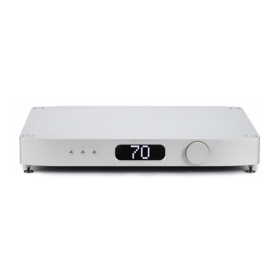
Setup and Quick Start The interface is quite simple with few user controls. Input source defaults to auto switching. The display will let you know if you have an active input. On power up, the volume is reset to the programmed startup level. -
Page 5: Front Panel User Interface
Front Panel User Interface Menu Button The square button is single purpose. It will enter the setup mode at the top of the menu tree. If in the setup, and it doesn’t matter where, this button will exit the setup and return to the normal operational mode. -
Page 6: Output Modules
About the 2 input module slots The DAC has two input module slots. They are labeled A and B. Input modules can be placed in any position. Each module is completely self contained. It is recognized by the DAC and identified on the display. -
Page 7: Module Handling
Removing and Installing Modules Removal and installation of modules is a completely tool free process that is easily performed at the back of the unit. Under the lower lip of each module is a lever arm. Simply pull the lever out and away until it is perpendicular with the back of the unit. -
Page 8: Setup Menu Options
Setup Menu Options Brightness This can be adjusted from 1 - 10 (Default 8) (Display brightness) Display On (Default) (Display On/Off) • The display is on continuously Auto off • The display is off but will turn on momentarily when information changes Volume 0 - 100 (Default 70) (Startup volume) - Page 9 Setup Menu Options (continued) Reset • This restores the DAC to default factory settings SN:DI###### This screen displays the DAC serial number Code This screen displays the currently installed firmware Saving Menu and Startup Settings When changing settings in the menu, use the enter button in the center of your volume wheel on the remote or the right arrow on the DAC faceplate to confirm settings in the DAC menu.
- Page 10 The MSB Remote Indicator LED While in use: White - Command Sent Red and White - Command Sent and Low Battery Red Flashing - Needs Charging While charging: Red - Charging White - Fully Charged Power Powerbase on and off. When the powerbase is linked to an amplifier or MSB product, this button will turn off the entire system...
-
Page 12: Loading New Firmware
Loading new firmware Always be certain that you are updated with the current firmware by checking our website. The DACs’ firmware is always updated using a .WAV file. If you experience issues with playback of the update file, be sure to check for bit-perfect playback in your system. All firmware updates can be found at: www.msbtechnology.com/Support Bit-Perfect Source Testing... - Page 13 Premier Powerbase Upgrade The powerbase contains isolation technology. The powerbase detects the input voltage and switches to 120 volt or 240 volt operation. It is also available in a fixed 100 volt configuration. All powerbases have over-voltage protection. Two fuses are provided: - 5A 250V SLO BLO - 5 mm x 20 mm miniature fuse (This is the main fuse).
-
Page 14: Grounding Diagram
Ground Jumper IN - Basic Operation The Basic Operation provides isolation only for the DAC. This gets you half the protection available. For full protection, be sure the jumper is in place between the Chassis Ground and Amplifier Ground. This is the shipping configuration. - Page 15 Powerbase - 12 Volt Remote Trigger This powerbase is equipped with a remote trigger for use with other MSB products. The trigger uses a 3 pin mini jack. When any MSB product is turned off, the other products connected will also turn off and vice-versa.
-
Page 16: Technical Support
Technical Support If you are experiencing any issues with your MSB product, please contact your nearest dealer or try our support page at www.msbtechnology. com/support. Please be sure you have the most current edition of your products firmware installed. If your issue persists please feel free to contact MSB directly. - Page 17 The Discrete DAC Limited Warranty Warranty includes: • MSB warrantys the unit against defects in materials and work- manship for a period of 1 year from the date the unit was originally shipped from MSB. • This warranty covers parts and labor only, it does not cover shipping charges or tax/duty.
Need help?
Do you have a question about the The Discrete DAC and is the answer not in the manual?
Questions and answers