D-Link DES-6500 Quick Installation Manual
Hide thumbs
Also See for DES-6500:
- User manual (353 pages) ,
- Manual (352 pages) ,
- Cli manual (334 pages)
Table of Contents
Advertisement
Available languages
Available languages
Quick Links
Introduction
This Quick Installation Guide gives step-by-step
instructions for installing modules in the D-Link
DES-6500 Modular Ethernet Switch. This switch is
used to connect an entire department to your
Ethernet backbone. For more detailed information
about the switch, its components, making network
connections,
configuration
specifications, please refer to the User's Guide
included in Adobe Acrobat format on the CD-ROM
that was included with the switch.
Step 1 – Unpacking
Please ensure your box contents included:
One switch networking module
This Quick Installation Guide
Step 2 - Hardware Installation
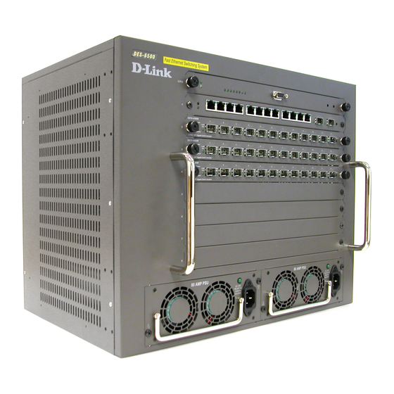
The DES-6500 ships as a base unit which includes:
DES-6501 Backplane Chassis –
provides electrical power to and conveys
transmissions between modules
DES-6502 CPU Module – Switching and
management module located in the
uppermost slot
DES-6511 Redundant Power Supply
Module – located in one of the two large
slots at the bottom of the switch
Networking modules sold separately include:
DES-6502 CPU module
DES-6504 12-port 100BASE-FX SFF Fast
Ethernet Switch module
DES-6505 8-port 1000BASE-SX SC
Gigabit Ethernet Switch module
DES-6506 24-port RJ45 Patch Panel
module
DES-6507 12-port 1000BASE-T + 2-port
Combo SFP slot Gigabit Ethernet Switch
module
DES-6508 16-port
10BASE-T/100BASE-TX (RJ45) Fast
Ethernet Switch module
DES-6509 12-port Mini GBIC Gigabit
Ethernet Switch module
DES-6510 24-port 10/100 RJ21Switch
module
DES-6511 Redundant Power Supply
module
Carefully follow the procedures defined below to
install modules in the switch. Networking modules
can be installed in any unused slot with the
and
technical
exception of the DES-6502 CPU module which must
be installed in the uppermost slot (only).
1.
Remove a blank slot cover.
2.
Carefully slide a module into the slot, making
sure that its sides are inside the guide rails.
3.
When the module reaches the back of the chassis,
push gently but firmly to connect the rear
sockets of the module to the backplane. Ensure
that the module is completely inserted into the
chassis such that its front panel is flush with the
front panel of the chassis.
4.
Tighten the two large module screws to ensure
that the module is held firmly in place.
Note: Networking modules are hot-swappable,
meaning they can be added and removed while power
to the switch is ON. The CPU module however, is
NOT hot-swappable. Removing or inserting the CPU
module while the power is on may cause irreparable
damage to the module and/or to the switch itself.
Further, make sure you have unplugged the power
cord from the removable power supply module before
inserting or removing it from the switch.
Advertisement
Table of Contents

Related Manuals for D-Link DES-6500


Summary of Contents for D-Link DES-6500
- Page 1 Step 2 - Hardware Installation Carefully slide a module into the slot, making sure that its sides are inside the guide rails. The DES-6500 ships as a base unit which includes: DES-6501 Backplane Chassis – provides electrical power to and conveys transmissions between modules ...
-
Page 2: Additional Information
United States and http://www.dlink.co.uk for Great Britain. URLs for D-Link Websites in other countries are contained in the list of D-Link Offices at the back of the User’s Guide. Einführung Diese Kurzanleitung hilft Ihnen Schritt für Schritt bei der Installation des DES-6500 Modular Ethernet Switch von D-Link. -
Page 3: Schritt 2 - Hardware Installieren
Ein Switch-Netzwerkmodul Diese Kurzanleitung zur Installation Schritt 2 – Hardware installieren Das DES-6500 wird als Grundeinheit geliefert und Schieben Sie das Modul vorsichtig in den umfasst: Steckplatz ein. Stellen Sie dabei sicher, dass es sich an den Seiten in den Führungsschienen ... -
Page 4: Ergänzende Hinweise
Introduction Ce Guide d’installation rapide vous donne des instructions détaillées pour l’installation des modèles du switch Ethernet modulaire DES-6500 de D-Link. Ce switch permet de connecter tout un service à votre dorsal Ethernet. Pour de plus amples informations concernant le switch, ses composants, la manière de... - Page 5 Un module réseau de switch Ce guide d’installation rapide Etape 2 – Installation du matériel Le DES-6500 est livré sous forme d’unité de base 10. Faites délicatement glisser un module dans la comprenant : fente, en vous assurant que ses côtés suivent ...
-
Page 6: Informations Complémentaires
Etats-Unis http://www.dlink.co.uk pour la Grande Bretagne. Les URL des sites web de D-Link dans les autres pays sont indiqués dans la liste des bureaux D-Link qui figure au dos du Guide d’utilisation. Introducción Esta Guía rápida de instalación contiene las instrucciones detalladas para la instalación de los... -
Page 7: Paso 1 - Contenido Del Paquete
Módulo conmutador de red. Guía rápida de instalación. Paso 2 – Instalación del hardware El DES-6500 es una unidad base que incluye: DES-6501 Chasis backplane – 14. Con cuidado, introduzca un módulo en el slot, Proporciona alimentación eléctrica a los asegúrese de que los laterales del módulo están... -
Page 8: Información Adicional
Estados Unidos, y en http://www.dlink.co.uk, para Gran Bretaña. Las direcciones web D-Link para otros países figuran en la lista de delegaciones D-Link, al final de la Guía del usuario. Introduzione Il presente manuale utente fornisce le istruzioni per installare i moduli nello switch Ethernet modulare D-Link DES-6500. - Page 9 1 modulo di rete dello switch Il presente manuale rapido d’installazione Fase 2 – Installazione hardware Il dispositivo DES-6500 viene fornito come unità base che include: 18. Inserire delicatamente lo slot nel modulo, Backplane Chassis DES-6501 – fornisce verificando che i lati siano inseriti nelle relative l’alimentazione elettrica e gestisce la...
-
Page 10: Informazioni Aggiuntive
Ulteriori informazioni sono disponibili online all’indirizzo per l’Italia. Gli indirizzo dei siti D-Link http://www.dlink.it degli altri paesi sono contenute nell’elenco degli uffici D-Link, riportato nell’ultima pagina del Manuale utente. -
Page 11: Шаг 1 - Распаковка
Один сетевой модуль коммутатора Данное Руководство по быстрой установке Шаг 2 – Установка модуля 20. Осторожно установите модуль в слот по DES-6500 допускает установку следующих модулей: направляющим. DES-6501 Backplane Chassis – объединительный блок, обеспечивает электропитание модулей и их взаимодействие... -
Page 12: Дополнительная Информация
пользователя на CD-ROM. В нем содержится перечень правил, схемы, пояснение многих понятий и примеры, помогающие настроить и запустить в эксплуатацию сеть. Дополнительная информация доступна на сайте Ссылки на http://www.dlink.ru. Web-сайты D-Link в других странах содержатся в списке офисов D-Link в конце Руководства пользователя. - Page 13 簡介 此快速安裝手冊指導您逐步在D-Link DES-6500模組 化乙太網交換器中安裝模組。該交換器用於將一個完整 的網路連接到乙太網路主幹。要詳細瞭解交換器及其元 件,網路連接,配置及技術規格等內容,請參考購買交 換器所附帶的光碟上Adobe Acrobat格式下的使用手 冊。 1 – 步驟 拆開包裝 請確認包裝盒中具有以下物品: 一個交換器網路模組 本快速安裝手冊 22. 小心地將模組插入插槽中 , 確認模組側邊位於導引軌 中。 步驟 硬體安裝 DES-6500是一部基本設備,它包括: DES-6501 背板機箱 –為模組及模組間傳輸 與提供電力。 DES-6502 CPU 模組 –交換和管理模組,位 於最上方的插槽。 DES-6511 備援電源模組–位於交換器底部兩...
Need help?
Do you have a question about the DES-6500 and is the answer not in the manual?
Questions and answers