Table of Contents
Advertisement
Quick Links
PERFORMANCE
DISCHARGE VOLUME........................................2.8 GPM / 10.6 LPM
PUMP HEAD PRESSURE....................................2000 PSI / 138 BAR
MINIMUM INLET WATER PRESSURE..................40 PSI / 0.68 BAR
WEIGHT (DRY) .........................................................110 LBS / 50 KG
SPRAY TIP.........................................(#4.5-15DEG) P/N J00-15045-2
SPRAY TIP..........................................(#20-15DEG) P/N J00-15200-2
HOSE, DISCHARGE..............................3/8" X 50' P/N K02-03150E1
WAND & TRIGGER GUN.......................................... P/N E320-00701
TRIGGER GUN ............................................................ P/N J06-00121
VOLTAGE .................................................................. 230V 1PH 60HZ
CURRENT ................................. 208V - 17.8 AMP / 230V - 16.6 AMP
CAM SWITCH ............................................................P/N F04-00735A
POWER CORDSET .................................................. P/N F04-00103A
Supersedes 03-27-05 Z08-02372S
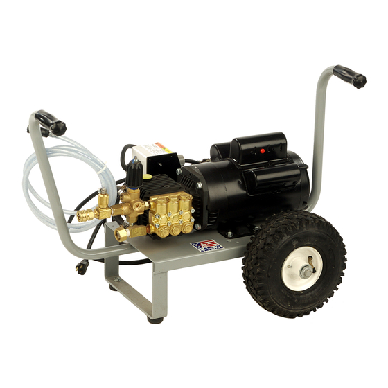
MODEL E320 (GENERAL), E320A (AR)
SPECIFICATIONS
PUMP & UNLOADER
PUMP - AR .................................................................. P/N N09-00016
PUMP - GENERAL ..................................................... P/N N07-00053
WATER FILTER .......................................................... P/N C04-00121
UNLOADER.............................................................. P/N C07-04200B
PUMP MOTOR
MOTOR HORSEPOWER........................................... 4.0 HP / 2.9 KW
MOTOR VOLTAGE .......................................... 208V/230V 60HZ 1PH
MOTOR ................................................................. P/N F02-00098-UC
ENGINE PULLEY........................................................ P/N R03-00530
MOTOR BUSHING.................................................. P/N R04-00007-H
05-31-05 Z08-02372S
Advertisement
Table of Contents
Troubleshooting

Related Manuals for ALKOTA E320


Summary of Contents for ALKOTA E320
- Page 1 SPRAY TIP..........(#20-15DEG) P/N J00-15200-2 MOTOR VOLTAGE .......... 208V/230V 60HZ 1PH MOTOR ..............P/N F02-00098-UC HOSE, DISCHARGE......3/8” X 50’ P/N K02-03150E1 WAND & TRIGGER GUN.......... P/N E320-00701 ENGINE PULLEY............P/N R03-00530 TRIGGER GUN ............P/N J06-00121 MOTOR BUSHING..........P/N R04-00007-H ELECTRICAL VOLTAGE ..............
- Page 2 MACHINE RECORD MAINTENANCE RECORD SERIAL NUMBER DATE OF PURCHASE PLACE OF PURCHASE NOTES: 01-08-04 Z08-04527 ECN-03022...
- Page 3 OPERATION TABLE OF CONTENTS ELECTRIC DRIVEN COLD WATER SAFETY INSTRUCTIONS TROUBLESHOOTING Page Number Page Number Machine 9, 10 Safety Symbols • • Pump See Parts List Section General • • Mechanical • SERVICE Electrical • Machine • INSTALLATION Pump See Parts Lists Section •...
- Page 4 SAFETY, INSTALLATION, AND OPERATION ELECTRIC DRIVEN COLD WATER CLEANER MACHINE UNPACKING GENERAL SAFETY ALL CLEANERS ARE CAREFULLY INSPECTED 1. Before operating this machine, read and observe AND CARTONED TO PROTECT AGAINST SHIPPING all safety, unpacking, and operating DAMAGE. IF THERE IS DAMAGE OR MISSING instructions.
- Page 5 4. If an extension cord must be used to operate WARNING: RISK OF INJECTION OR this machine, it should be as short as possible. SEVERE INJURY. KEEP CLEAR OF The extension cord must be properly sized and NOZZLE. DO NOT DIRECT DISCHARGE fitted with a grounding type plug and STREAM AT PERSONS.
- Page 6 “Acceptable for use with outdoor appliances; ELECTRICAL INSTALLATION store indoors while not in use.” Use only extension cords having an electrical rating not less than the rating of the product. Do not use 1.ELECTRICAL: Connect machine to an damaged extension cords. Use an extension electrically grounded circuit that is fused or cord in good repair free of frays or cracks in circuit breaker protected.
- Page 7 2. To CLEAN: ♦ ELECTRICAL: Connect the machine to an A. Start on the lower portion of the area to be electrically grounded circuit that is fuse or cleaned and work up using long, even, circuit breaker protected. Do not use any type overlapping strokes.
- Page 8 MACHINE MAINTENANCE ELECTRIC DRIVEN COLD WATER CLEANER FLUSHING Fill a 1-gallon container with Ethylene Glycol type antifreeze. Minimum should be a mixture Connect machine to an electrically grounded of ½ antifreeze and ½ water strength before each circuit that is fuse or circuit breaker use, as the antifreeze will dilute with each use.
- Page 9 MACHINE MAINTENANCE EACH AFTER EVERY EVERY EVERY ELECTRIC DRIVEN COLD FIRST DAILY YEARLY FIRST WATER CLEANERS 8 HRS OIL BATH WATER PUMP: Oil Level – check and add as needed per PUMP SERVICE insert. Oil Change – drain and refill per PUMP .
- Page 10 CLEANER TROUBLESHOOTING ELECTRIC MOTOR DRIVEN COLD WATER CLEANERS TROUBLE POSSIBLE CAUSE REM E DY 1. Poor Cleaning A. Hard water. A. Connect machine to water softener. Action. B. Low Pressure. B. See "Low operating pressure" C. Little or no chemical being C.
- Page 11 CLEANER TROUBLESHOOTING (CONT.) ELECTRIC MOTOR DRIVEN COLD WATER CLEANERS T R O U B L E P O S S I B L E C A U S E R E M E D Y A . S e e P U M P T R O U B L E S H O O T I N G . 4.
- Page 15 PUMP HEAD REMOVAL PUMP HEAD REINSTALLATION...
- Page 17 PUMP TROUBLESHOOTING TROUBLE POSSIBLE CAUSE REMEDY 1. Oil leaking in the A. Worn crankshaft seal. A. Remove and replace. area of water pump B. Bad bearing. B. Remove and replace. crankshaft. C. Grooved shaft. C. Remove and replace. D. Failure of retainer o-ring D.
- Page 18 PUMP TROUBLESHOOTING TROUBLE POSSIBLE CAUSE REMEDY 9. Dirty or worn check A. Normal wear. A. Remove and replace. valves. B. Debris B. Check for lack of water inlet screens. 10. Presence of metal A. Failure of internal component. A. Remove and disassemble to find particles during oil probable cause.
- Page 22 NOTE: When plunger nut is removed, install a new copper washer and flinger washer to ensure proper fit and seal of ceramic plunger. If same copper washers are reused cracking or a poor seal may result.
- Page 24 GENERAL PUMP MAINTENANCE OIL LEVEL 6. Malfunctioning valve assemblies must be replaced. 7. Lubricate a new o-ring with the pump crankcase oil and install into valve cavity in the head. Install a good valve assembly into the cavity as illustrated. 8.
- Page 25 GENERAL PUMP MAINTENANCE PLUNGER SERVICE PLUNGER INSTALLATION 1.Remove pump head per “HEAD REMOVAL”. 2.Remove any packings and retainers left on the plungers 1. Install the copper flinger washer onto the cross head. by pulling them straight off. 2. Slide the plunger onto the crosshead. 3.Examine each plunger, looking for a smooth surface free 3.
- Page 26 GENERAL PUMP MAINTENANCE HEAD INSTALLATION 9. Install the restop ring with the lips pointing down. 10. Install a front female adapter into each cavity with the flat side up. Make certain the adapter goes all way 1. Prepare pump head per instructions in “PACKING down into the cavity.
- Page 27 PUMP MAINTENANCE RECORD OIL CHANGE MONTH / DAY / YEAR OPERATING HOURS OIL BRAND & TYPE PUMP SERVICE MONTH / DAY / YEAR OPERATING HOURS TYPE OF SEVICE Supersedes 03-27-02 Z08-03516 08-24-04 Z08-03516...
- Page 28 PUMP TROUBLESHOOTING TROUBLE POSSIBLE CAUSE REMEDY 1. Oil leaking in the A. Worn crankshaft seal. A. Remove and replace. area of water pump B. Bad bearing. B. Remove and replace. crankshaft. C. Grooved shaft. C. Remove and replace. D. Failure of retainer o-ring D.
- Page 29 PUMP TROUBLESHOOTING TROUBLE POSSIBLE CAUSE REMEDY 9. Dirty or worn check A. Normal wear. A. Remove and replace. valves. B. Debris B. Check for lack of water inlet screens. 10. Presence of metal A. Failure of internal component. A. Remove and disassemble to find particles during oil probable cause.
- Page 30 MAXIMUM FLOW ....6.6 GPM / 24.6 LPM MAX UNLOADING PRESS..3650 PSI / 251.6 BAR MAXIMUM TEMPERATURE....195° / 91°C WEIGHT........1.0 LBS. / 0.45 KG BYPASS...........3/8 FNPT INLET............1/4 NPT OUTLET.............3/8 NPT 1. Install an appropriate pressure gauge in pump head outlet. The gauge should have a pressure range of twice the operating pressure.
- Page 34 2 11/16" 3 1/8"...
- Page 35 SWITCH PUMP MOTOR 230 VAC...
Need help?
Do you have a question about the E320 and is the answer not in the manual?
Questions and answers