Seca 264 Manual
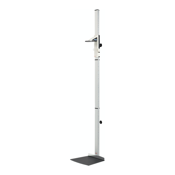
Length measuring rod
Hide thumbs
Also See for 264:
- Instruction manual and guarantee (275 pages) ,
- Mounting instructions (4 pages) ,
- Service manual (67 pages)
Table of Contents
Advertisement
Advertisement
Table of Contents

Related Manuals for Seca 264


Summary of Contents for Seca 264
- Page 1 264...
-
Page 2: Table Of Contents
....44 seca wireless groups ..66 3. Overview ....45 Channels . -
Page 3: Description Of Device
1.2 Intended use The seca 264 length measuring rod is mainly used in hospitals, doctors' surgeries and inpatient care facilities, in accordance with national regulations. The length measuring rod is used to determine a baby's size. -
Page 4: Safety Information In This Manual
English • Make sure you only use genuine seca accessories and spare parts. Otherwise the warranty provided by seca will become null and void. • Make sure RF equipment such as mobile phones is kept at a minimum distance of approx. 1metre to prevent incorrect measurements or interference with the wireless transmission. -
Page 5: Batteries
2.3 Handling (rechargeable) batteries The device is supplied with 4 batteries, type AA (Mignon). This type of battery is not rechargeable. Please take note of the following safety information. WARNING! Personal injury with improper handling. Batteries contain harmful substances which may explode if not handled properly. -
Page 6: Overview
English 3. OVERVIEW 3.1 Controls Overview • 45... - Page 7 Control Function Head slide Control for determining height Keypad, head Controls for performing length/height measurements and slide for configuring the device Frankfurt Pull-out ruler for aligning the head according to the so- measure called “Frankfurt Horizontal”. Display, head Display element of the head slide for measured results slide and for configuration Battery...
-
Page 8: Display Elements
English Display elements Symbol Meaning Battery power low. 3.3 Information on rating plate Text/Symbol Meaning Model Model number Type Type designation Ser.No. Serial number Refer to user manual Type B electromedical device Class II fully-insulated appliance For USA: FCC ID device licensing number issued by the US Federal Communications Commission (FCC) For Canada:... -
Page 9: Menu Structure
Channel 3 (C3) • Autosend • seca 360° wireless network: • System Group (ID): • Max. three seca wireless groups: 0, 1, 2 • Autoprint Maximum configuration per wireless • group: - 1 set of baby scales • Year •... -
Page 10: Before You Get Started
English 4. BEFORE YOU GET STARTED … 4.1 Scope of supply Component Qty. Bottom column element with heel stop Column element Threaded rod Upright connector End cap Elongated nut Plain washer Decorative cap Wall-mounting kit consisting of - Wall brackets - Slot bolts - Screws M6 x 60 - Standard rawl plugs... -
Page 11: Assembling The Device
4.2 Assembling the device The heel stop is mounted on the first column element in the factory. Perform the remaining assembly with the assistance of another person. Due to the large overall height, we recommend placing the components on the floor and not uprighting the device until it is fully assembled. -
Page 12: Installing The Head Slide
English Installing the head slide To position the head slide on the upright, proceed as follows: 1. Tilt the head slide slightly towards the front. ATTENTION! Damage to device due to incorrect handling Incorrect handling can damage the claw guide of the head slide. -
Page 13: Installing The Push-In Scale
Installing the push-in ATTENTION! Incorrect measurements due to installation scale errors If the push-in scale is installed incorrectly the head slide cannot determine any usable readings. − Align the push-in scale so that the printing remains visible when the scale is pushed into the groove. -
Page 14: Mounting The Device On The Wall
English 4.3 Mounting the device on the wall Choose an adequately strong, load-bearing wall to mount the device. Standard rawl plugs are supplied for installation on solid brick walls. We recommend use of appropriate special rawl plugs for other types of walls. Due to the special design, the installation height of the wall brackets can be freely selected. -
Page 15: Installing The Slot Bolts
4. Remove the slot bolts from the wall brackets. 5. Mount the wall brackets using the screws (M6x60). 6. Use a spirit level to align the wall brackets perpendicularly with each other. 7. Tighten the screws of the wall brackets. Installing the slot bolts To install the slot bolts, proceed as follows: 1. -
Page 16: Positioning The Device In The Wall Brackets
English Positioning the device To position the device in the wall brackets, proceed as follows: in the wall brackets 1. Position the device with the slot bolts in the wall brackets. 2. Use a spirit level to perpendicularly align the device. 3. -
Page 17: Connecting The Power Supply
4.4 Connecting the power supply The head slide is supplied with power from batteries. The batter holder supplied already contains 4 Mignon batteries, type AA, 1.5 volt. To connect the power supply for the head slide, proceed as follows: 1. Remove the cover of the battery compartment. 2. - Page 18 English 2. Keep the brake button pressed and move the head slide until a length value appears in the display. ATTENTION! Incorrect measurement as a result of incomplete calibration. The height value displayed does not correspond to the actual position of the head slide.
-
Page 19: Calibrating Manually
Calibrating manually If the calibration rod is not to hand, you can perform the calibration manually using another object of known height. 1. Press the Start key of the head slide. “----” appears in the display. 2. Keep the brake button pressed and move the head slide until a length value appears in the display. -
Page 20: Operate Head Slide
If you want to transmit the measured result to receivers from the system, seca 360° wireless ensure that the receivers are switched on. 2. Keep the brake button pressed and move the head slide until a length value appears in the display. -
Page 21: Continuous Display Of Measured Result (Hold)
9. Read off the height on the head slide display. 10. Press the Enter key (send/print) to transmit the height to receivers from the seca 360° wireless system. – Press key briefly: send measured results to all receive-ready devices –... -
Page 22: Transmit Measured Results To Wireless Receivers
English 5. Reposition the head slide. Length (height) is measured relative to the set zero point. If the zero point is undershot, the measured values are shown with a minus sign in front of them. 6. To disable the "ZERO" function, keep the arrow key (hold/zero) pressed until the "ZERO"... -
Page 23: Additional Functions (Menu)
5.2 Additional functions (menu) Additional functions are available in the device's menu. This allows you to configure the device to suit your own needs perfectly. • Beep • Auto …. Reset • Short Duration • Long • 50 % • 100% Brightness •... -
Page 24: Activate Acoustic Signals (Beep)
English 5. To change the setting or to call up another submenu, keep pressing the arrow key (hold/zero) until the required setting (here: display brightness “bri”) is displayed. 6. Confirm your selection with the Enter key (send/ print). The current setting for the menu item or a submenu is displayed (here: “display brightness 50%”). -
Page 25: Set Display Backlighting (Lcd)
Function Factory setting Autoprint (APrt) Length units (Unit) NOTE The wireless module is switched off when factory settings are restored. Information about existing wireless groups is retained. Wireless groups do not have to be set up again. 1. Select the item "rSEt" from the menu. 2. -
Page 26: Switch Over Length Units (Unit)
English Switch over length units You can select the units (Unit) you wish to use for displaying the height. (Unit) NOTE • This function is not available with all model variants. • Note and follow the national regulations regarding units of measurement. 1. -
Page 27: The Seca 360° Wireless Network
The following combination of devices is possible for each wireless group: • 1 set of baby scales • 1 set of personal scales • 1 length measuring rod • 1 seca wireless printer • 1 PC with seca USB wireless module 66 •... -
Page 28: Channels
• 1: personal scales • 2: height-measuring rod • 3: wireless printer • 4: PC with seca USB wireless module • 7: baby scales • 5, 6 and 8-12: reserved for system expansion The seca 360° wireless network • 67... -
Page 29: Operating The Device In A Wireless Group (Menu)
6.2 Operating the device in a wireless group (menu) All the functions required to operate the device in a seca wireless group can be found in submenu "rF". …. • Channel 1 (C1) Learn Room (ID) • Channel 2 (C2) Stop Reg. - Page 30 10. Confirm your selection for channel 3. StOp message appears in the display. The device is waiting for signals from other devices with wireless transmission capability within range. The seca 360° wireless network • 69...
-
Page 31: Activate Automatic Transmission
NOTE With certain devices, a special switch-on procedure must be followed if they are to be integrated in a wireless group. Consult the user manual for each device. 11. Switch on the device you wish to integrate in the wireless group, e.g. a wireless printer. A beep can be heard when the wireless printer is detected. -
Page 32: Select Print Option (Aprt)
NOTE This function is only available if the "learn" function has been used to integrate a seca wireless printer in the wireless group. 1. Switch on the length measuring device and the scales. 2. Select the "APrt" menu item from the "rf" submenu and confirm your selection. -
Page 33: Cleaning
Cause/Remedy … a segment lights up There is a fault at that point. continuously or not at - seca notify the service department. all? Battery voltage is falling off. The background ...the background lighting has been automatically switched off to lighting of the display save energy. - Page 34 (Lrn)” on page 68). • The device was unable to send measured results to the wireless receiver (seca wireless printer or PC with seca USB wireless module). – Check that the device is integrated in the wireless network.
-
Page 35: Change The Batteries Of The Head Slide
Malfunction Cause/Remedy … when the Enter key is Data transmission not possible, wireless module is pressed and the disabled. Er:x:71: display - Activate wireless module (see “Activate wireless module (system)” on page 68). appears? … when the Enter key is Data transmission is not possible, no wireless pressed and the group set up. -
Page 36: Maintenance
English 9. MAINTENANCE We recommend having it serviced every 3 to 5 years depending on how often the scales are used. ATTENTION! Incorrect measurements due to improper servicing − Make sure that maintenance and repair are only carried out by an authorised service partner. -
Page 37: Accessories
Article number Wireless network seca 360° wireless • wireless printer country-specific variants seca 360° Wireless Printer 465 country-specific variants seca 360° Wireless Printer Advanced 466 • PC software Application-specific licensed seca analytics 105 models • USB wireless module 456-00-00-009 seca 360° Wireless USB adapter 456 12.DISPOSAL... -
Page 38: Warranty
The warranty shall become null and void where the device is opened by persons not expressly authorised to do so by seca. We ask customers based abroad to contact their local sales agent direct in the case of warranty claims. - Page 39 78 •...
Need help?
Do you have a question about the 264 and is the answer not in the manual?
Questions and answers
We are pediatric office and our SECA 264 stadiometer is just over 2 years old, and the head slide is broken. Are there replacement parts available? Thank you.