
Subscribe to Our Youtube Channel
Related Manuals for JUKI UnionSpecial 35800DLU


Summary of Contents for JUKI UnionSpecial 35800DLU
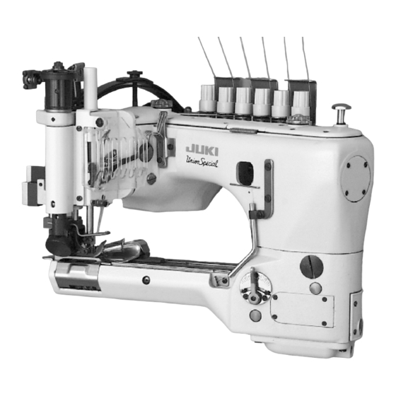
- Page 1 ADJUSTING INSTRUCTIONS / ILLUSTRATED PARTS LIST 35800 High Speed Feed- Off- The- Arm With Plain Feed Differential Feed MANUAL NO. PT9804-GR STYLES 35800DLU 35800DNU 35800DRU 35800DRW 35800DWW 35800PZ 35800DZ REV 01/14/08...
- Page 2 Manual No. PT9804-GR Adjusting Instructions & Illustrated Parts List for 35800 Series Machines First Edition Copyright 2007 Union Special Corporation Rights Reserved In All Countries Printed in U.S.A. August 2007 PREFACE This parts manual has been prepared to assist you in locating individual parts or assemblies on 35800 Series machines. It is the desire of Union Special that each machine run at its optimum performance.
-
Page 3: Table Of Contents
CONTENTS IDENTIFICATION OF MACHINES ..................................... 2 SAFETY RULES .......................................... 4 CLASS DESCRIPTION ......................................5 STYLE OF MACHINES ......................................5 ILLUSTRATIONS ........................................6 IDENTIFYING PARTS ......................................... 6 NEEDLES ..........................................6 TERMS ............................................6 THREADING & OILING FOR PLAIN FEED ................................7 THREADING &... -
Page 4: Safety Rules
SAFETY RULES 1. Before putting the machines described in this manual into service, carefully read the instructions. The starting of each machine is only permitted after taking notice of the instructions and by qualified operators. IMPORTANT! Before putting the machine into service, also read the safety rules and instructions from the motor supplier. -
Page 5: Class Description
ICLASS DESCRIPTION High Speed, Feed-Off-The-Arm High Throw Machines, Two and Three Needle, Left Needle In Front. Light Weight Presser Bar Mechanism, Adjustable Looper Avoid, Space in Front of Needles 8" (203.2 mm), Single Disc Looper Thread Take-Up, Automatic Enclosed Type Oiling System and Filter Type Oil Pump, Visual Sight Oil Action and Supply Gauges. STYLE OF MACHINES 35800DLU DOUBLE LAP SEAM. -
Page 6: Illustrations
ILLUSTRATIONS This manual has been arranged to simplify ordering repair parts. Exploded views of various sections of the mechanism are shown so that the parts may be seen in their actual position in the machine. On the page opposite the illustration will be found a listing of the parts with their part numbers, description and the number of pieces required in the particular view being shown. -
Page 7: Threading & Oiling For Plain Feed
THREADING & OILING FOR PLAIN FEED FIG. 1A... -
Page 8: Threading & Oiling For Differential Feed
THREADING & OILING FOR DIFFERENTIAL FEED FIG. 1B... -
Page 9: Needles
i r c a l i t n i Table 1 NEEDLES Selection of proper needle size is determined by size of thread used. Thread should pass freely through the needle eye in order to produce a good stitch formation. Each needle has both a type and size number. -
Page 10: Synchronizing Needle And Looper Motions
SYNCHRONIZING NEEDLE AND LOOPER MOTIONS NOTE: Needle and looper mechanisms are carefully synchronized with pre- cision gauges before leaving the factory to insure the best possible sewing conditions. Should it become necessary to disassemble the main shaft or replace compo- nents of the needle or looper drive mechanisms, re-synchronization of the machine will be required to facilitate proper sewing adjustments. -
Page 11: Tightening Needle Head
TIGHTENING NEEDLE HEAD When replacement of the needle bar, and or needle head is neces- sary, torque the needle head to needle bar 14-16 in. lbs. (1.6-1.8Nm) or use torque rod No. 21227AR that has been supplied with the machine, for the purpose of eliminating the possibility of distorting the needle bar due to overtightening. -
Page 12: Setting The Looper (Cont.)
SETTING THE LOOPER (CONT.) If more or less looper avoid motion is required, remove cylinder side cover (A, fig. 8) located at the lower front left side. For plain feed use a screwdriver to loosen looper avoid link ball joint (B). For differential feed use Union Special wrench TT85 and loosen screw stud (C) Moving ball joint down in the lever slot increases the amount of looper avoid motion, moving it up acts the... -
Page 13: Setting The Feed Dogs For Differential Feed (Cont.)
SETTING THE FEED DOGS FOR DIFFERENTIAL FEED (CONT.) If adjustment is necessary loosen screw (E, Fig. 11A) in feed dog support (C) and move as required. Retighten screw (E). differential feed dog (A) may then be leveled with main feed dog (B). -
Page 14: Presser Foot And Presser Bar Adjustment
PRESSER FOOT AND PRESSER BAR ADJUSTMENT Adjusting or Replacing Presser Foot: Remove presser bar leaf spring (B, Fig. 14) and nut (B). Loosen screw (A, Fig. 15) on presser bar guide (B). Loosen screws (C) in upper collar and screws (D) in needle lever thread pull-off lever.. Slide presser bar upward high enough to slip on presser foot yoke (E) with foot attached and tighten screw (F) on flat of presser bar. -
Page 15: Upper Feed Roller Adjustment (Cont.)
UPPER FEED ROLLER ADJUSTMENT (CONT.) When feed roller mechanism (C, Fig. 17) has been re- moved or replaced, .003" (0.08mm) minimum to .005" (0.13mm) maximum clearance should be maintained between roller and throat plate. To Adjust Guiding System for Roller: Loosen two screws (A). -
Page 16: Setting Needle Thread Take-Up And Frame Eyelet
SETTING NEEDLE THREAD TAKE-UP AND FRAME EYELET With the needle bar at the top of its stroke set the adjustable frame needle thread eyelet (A, Fig. 20) in the lower mounting hole of eyelet (B) so the needle thread from eyelet (A) to the needle lever thread eyelet (C) will be in a straight line. -
Page 17: Folder Adjustment
FOLDER ADJUSTMENT Slide folder (A, Fig. 22) on arm. The folder should be as close to the front of presser foot (B) as possible, making sure to avoid the presser foot contacting the folder when sewing across seams. If adjustment is necessary loosen screws (C) to move entire folder left to right or front to back as required. -
Page 19: Main Frame, Cast-Off Plate, Eyelets, Miscellaneous Covers And Bushings
MAIN FRAME, CAST-OFF PLATE, EYELETS, MISCELLANEOUS COVERS AND BUSHINGS Ref. Amt. Part No. Description Req. Screw ......................29476XK Chamber Cover Assembly ................35882NR Crank Chamber Cover ................. 660-212 "O" Ring ................... 22924708 Oil Sight Gauge ................35878F Presser Spring ..................35888M Gasket .................... -
Page 21: Main Frame, Cast-Off Plate, Eyelets, Miscellaneous Covers And Bushings (Cont.)
MAIN FRAME, CAST-OFF PLATE, EYELETS, MISCELLANEOUS COVERS AND BUSHINGS (CONT.) Ref. Amt. Part No. Description Req. 1. thru 42. See preceding page. 35853W Looper Throw-Out Plunger ................35890R Bearing Housing Assembly ................660-764 Lip Seal ....................660-935 "O" Ring ....................50311C Ball Bearing .................... -
Page 23: Cylinder Covers And Bushings For Plain Feed
FOLDER, CYLINDER COVERS AND BUSHINGS FOR PLAIN FEED Amt. Ref. Description Req. Part No. 35883G Pin ....................... 35883H Cylinder Hinged Cover ................Screw Pin ....................22791E 35883E Spring ......................Screw ......................35796C Chain Cutter Blade, lower ................35796B Chain Cutter Blade, upper ................. 22747 Screw ...................... - Page 25 FOLDER, CYLINDER COVERS AND BUSHINGS FOR PLAIN FEED (CONT.) Amt. Ref. Description Req. Part No. 1. thru 30. See preceding page. 8372A Washer ......................22539H Plug Screw ....................660-1115 "O"Ring ......................22539AL Plug Screw ....................35897AX Gasket ......................22733A Oil Drain Plug Screw ..................35886B Gasket ......................
-
Page 27: Cylinder Covers And Bushings For Differential Feed
FOLDER, CYLINDER COVERS AND BUSHINGS FOR DIFFERENTIAL FEED Ref. Amt. Part No. Description Req. 22524 Screw ......................-------- Throat Plate (see page 51) ................22798 Screw ......................35883N Folder Gib, left .................... 35883P Folder Gib, right ..................22564J Screw ......................35883AA Gasket ...................... - Page 29 FOLDER, CYLINDER COVERS AND BUSHINGS FOR DIFFERENTIAL FEED (CONT.) Ref. Amt. Part No. Description Req. 1. thru 36. See preceding page. 36237L Bushing, for feed bar eccentric stud ............660-1117 Oil Seal ......................35850G Looper Shaft Bushing, rear ................35883G Pin .......................
-
Page 31: Detachable Head Assembly
DETACHABLE HEAD ASSEMBLY Amt. Ref. Description Req. Part No. Detachable Head Assembly ................ 35829AP Lower Needle Bar Bushing ..............35854B Presser Bar Bushing ................35844N Bushing ....................35844T Set Screw ....................SS8120740SP Presser Bar Bushing ................35878H 35854A Upper Needle Bar Bushing ..............Plate, baffle .................... -
Page 33: Oiling, Needle Lever, Crankshaft And Main Shaft Parts
OILING, NEEDLE LEVER, CRANKSHAFT AND MAIN SHAFT PARTS Amt. Ref. Description Req. Part No. 35894V Oil Reservoir, back ..................35897BU Oil Reservoir Outlet Tube ................29472AD Oil Pump Assembly for 35800DLU, DNU, DWW, DZ ........29472AA Oil Pump Assembly for 35800DRU, DRW, PZ ..........22585A Screw .................... -
Page 35: Plain Feed Bar, Feed Lift & Feed Drive Components For Plain Feed
PLAIN FEED BAR, FEED LIFT & FEED DRIVE COMPONENTS FOR PLAIN FEED Amt. Ref. Description Req. Part No. 22874CA Screw ......................------ Feed Dog (see page 51) ................35834U Feed Dog Holder ..................Screw, for adjusting feed dog height ............ 35834V3 Feed Dog Holder Shim ................. -
Page 37: Differential Feed Bar, Main Feed Bar, Feed Lift Eccentric Assembly For Differential Feed
DIFFERENTIAL FEED BAR, MAIN FEED BAR, FEED LIFT ECCENTRIC ASSEMBLY FOR DIFFERENTIAL FEED Amt. Ref. Description Req. Part No. 22528 Screw ......................------ Differential Feed Dog (see page 51) ............Screw ......................35825AC Needle Guard ..................... 22768 Screw ......................35835B Needle Guard Holder ................. -
Page 39: Feed Drive Components, Looper Drive Components And Loopers For Plain Feed
FEED DRIVE COMPONENTS, LOOPER DRIVE COMPONENTS AND LOOPERS FOR PLAIN FEED Amt. Ref. Description Req. Part No. 35848E Looper Holder, for middle looper, marked "D" ........... 22564P Screw ....................22562A Screw ....................35848D Looper Holder, for left looper, marked "C" ..........22564P Screw .................... -
Page 41: Loopers, Looper Holders, Feed Drive Components And Looper Avoid Components For Differential Feed
LOOPERS, LOOPER HOLDERS, FEED DRIVE COMPONENTS AND LOOPER AVOID COMPONENTS FOR DIFFERENTIAL FEED Ref. Amt. Part No. Description Req. 35848B Looper Holder, for Right looper, marked "A" ..........22564P Screw ....................22562A Screw ....................35848E Looper Holder, for Middle looper, marked "D" ..........22564P Screw .................... -
Page 43: Upper Roller Feed, Foot Lifter And Thread Tension Parts
UPPER ROLLER FEED, FOOT LIFTER AND THREAD TENSION PARTS Amt. Ref. Description Req. Part No. 36280V Lifter Lever Link Assembly ................36280U Lifter Lever Link ..................22585C Screw ..................... Screw ......................35892A Puller Bar Knob, rear ..................50377L Spring, puller bar ..................22758C Screw ...................... -
Page 45: Upper Roller Feed, Foot Lifter And Thread Tension Parts (Cont.)
UPPER ROLLER FEED, FOOT LIFTER AND THREAD TENSION PARTS (CONT.) Amt. Ref. Description Req. Part No. 1. thru 34. See preceding page. 22758C Screw ......................Presser Bar Lifter Lever ................. 35880N 35880P Lifter Lever Bell Crank .................. 22894J Screw ....................35878H Presser Bar Spring and Regulator .............. -
Page 47: Pulley, Crankshaft, Clutch And Clutch Driving Mechanism
PULLEY, CRANKSHAFT, CLUTCH AND CLUTCH DRIVING MECHANISM Ref. Amt. Part No. Description Req. 35822W CrankShaft ....................29480ALY Connecting Rod and Clutch Driving Eccentric Assembly ......35877XA Eccentric ....................22894C Screw ..................... 666-186 Oil Wick ....................50342V Shoulder Screw ..................22589 Screw ...................... -
Page 49: Pulley, Crankshaft, Clutch And Clutch Driving Mechanism (Cont.)
PULLEY, CRANKSHAFT, CLUTCH AND CLUTCH DRIVING MECHANISM (CONT.) Ref. Amt. Part No. Description Req. 1. thru 33. See preceding page Nut ......................29478BY Constant Wedge Angle Clutch Assembly ........... Nut ......................11638M Nut ......................61351C Washer ....................54274N Brake Spring ..................605A Screw .................... -
Page 51: Sewing Parts
SEWING PARTS Amt. Ref. Description Req. Part No. 35830DY Presser Foot Fork ..................22894BJ Screw ....................35830K Spring ......................22599 Screw ......................22845A Screw ......................35830DL9 Presser Foot, for Style 35800DLU9 ..............35830DM8 Presser Foot, for Style 35800DNU8, DZ32 ............35830DM9 Presser Foot, for Style 35800DNU9 DZ36 ............ -
Page 53: Thread Stand
THREAD STAND Amt. Ref. Description Req. Part No. GR-21101S7 Thread Stand, complete ................Thread Stand Base ................Screw ....................Nut ......................Screw ....................Thread Stand Rod, short ................ Base Bracket ..................Screw ....................Nut ......................Joint ...................... Nut ......................Holder, large ..................Screw .................... -
Page 54: Accessories
ACCESSORIES Ref. Part Amt. Description Req. TT85 Wrench, for looper avoid ..............21388AZ Wrench, for feed bar ................21227AR Needle Head Torque Rod ..............660-240 Thread Tweezers ................. 21201 Screwdriver ..................28604R Oil Can (not shown) ................660-1012 Oil Nozzle (not shown) ................ 660-457 Plastic Cover (not shown) .............. -
Page 55: Numerical Index Of Parts
NUMERICAL INDEX OF PARTS Part No. Page No. Part No. Page No. Part No. Page No. Part No. Page No. 1 0 9 ....4 5 22596 ...27, 29 23421Y9-3/32 ..29 35761D ....21... - Page 56 NUMERICAL INDEX OF PARTS Part No. Page No. Part No. Page No. Part No. Page No. Part No. Page No. 35830DY .....51 35851A ....39 35878H ..31, 45 3 5 8 9 5 W ....3 3 35830K ....51 35851G ....39 35878W ....43...
-
Page 57: Numerical Index Of Parts
NUMERICAL INDEX OF PARTS Part No. Page No. Part No. Page No. Part No. Page No. 36284F ....2 9 605 ....31 9937 ....31 36286 ....27 605A ....49 999-196 ....29 36286B ....27 61321J ....47 C067E ....21 36290B ....21 61321L ....47 CL21 .....21, 31 36292K ....45 61351C ..47, 49... -
Page 58: Notes
NOTES... - Page 59 NOTES...
Need help?
Do you have a question about the UnionSpecial 35800DLU and is the answer not in the manual?
Questions and answers