
Related Manuals for JUKI 35800 Series


Summary of Contents for JUKI 35800 Series
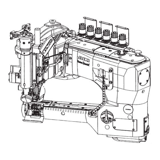
- Page 1 ® Feed-off-the arm, 3-Needle, Double Chainstitch Machine 35800 Series ENGINEER’S MANUAL 40052737 No.E376-00...
- Page 2 Introduction This Engineer’s Manual is written for the technical personnel who are responsible for the service and mainte- nance of the machine. The maintenance services to be done on this sewing machine should be based on this manual. This manual gives the "Standard Adjustment" on the former section under which the most basic adjustment value is described and on the latter section the "Results of Improper Adjustment"...
-
Page 3: Table Of Contents
CONTENTS 1. Specifications ......................1 (1) Roller mechanism/clutch type ....................1 (2) Roller mechanism/belt type ....................2 2. Model list ........................ 3 (1) Model list using the roller mechanism of the clutch type........... 3 (2) Model list using the roller mechanism of the belt type ............3 Description of US model code .............. - Page 4 (15) Adjustment of needle thread path..................38 1) Height of needle thread adjusting path ....................38 2) Height of rocking take-up path ......................38 3) Height of needle thread guide adjuster ....................38 (16) Adjustment of bobbin thread cam ..................40 (17) Adjustment of tension disk rise ..................42 (18) Adjustment of air nozzle (air blow) ..................
-
Page 5: Specifications
Lubrication Automatic rotary pump lubrication system Union Special Spec 175 (ISO grade 22) or Lubricating oil JUKI OIL SUP2000-1L Front tank capacity: 70 to 80 ml Oil tank capacity Rear tank capacity: 60 to 70 ml Pedestal type Installation... -
Page 6: Roller Mechanism/Belt Type
Lubrication Automatic rotary pump lubrication system Union Special Spec 175 (ISO grade 22) or Lubricating oil JUKI OIL SUP2000-1L Front tank capacity: 70 to 80 ml Oil tank capacity Rear tank capacity: 60 to 70 ml Pedestal type Installation... -
Page 7: Model List
Rubber type wide 3.6+3.6 0.8 mm of AY18-1/8 35800BWW9 7 to 12 stitches roller (35826DZ) Wide 2.4mm (35826X) unevenness For heavy-weight to extra-heavy-weight materials 7.2mm * In regard to the JUKI part numbers, refer to [10. Maintenance-(1) Spare parts.] – 3 –... - Page 8 MEMO – 4 –...
-
Page 9: Description Of Us Model Code
3. Description of US model code Model name: Feed-off-the-arm, 3-Needle, Double Chainstitch Machine Code Puller drive Code Classification of needle gauge 3.2mm Belt type 3.6mm Clutch type (mechanical type) 3.2mm Same as "D", only for PZ 3.6mm Code Application and outline Differential feed mechanism/Double lap seam/For light- and medium- weight materials (denim fabric of 6 to 9 oz.)/1 mm of throat plate un- evenness/Standard type wide roller equipped/Denim, jacket, working... -
Page 10: Description Of Model Code
4. Description of model code Machine name: Feed-off-the-arm, 3-needle, double chainstitch machine 3 5 8 0 0 – A A 6 to 10 Name Differential motion Stitch Needle Unevenness Sewing material Puller drive Roller width Roller shape gauge count of throat plate For light- and medium- 3.6mm weight materials (6 to 9 oz.),... -
Page 11: Names Of Machine Head
5. Names of machine head Belt drive upper feed roller Clutch drive upper feed roller End cover Gear cover (front) Clutch rod Bobbin thread guide pipe Gear cover (rear) Clutch lever Differential regulation lever Swing guard Cover for needle bar and roller Window screw for stitch length adjustment Upper feed roller assembly Pressure regulating nut... -
Page 12: How To Pass The Threads
6. How to pass the threads (1) Differential feed How to pass the needle threads and looper threads 1. Drawing of differential feed threading (sample model: 35800DNU & BWDN) Needle thread: 1 for left needle thread, 2 for middle needle thread, 3 for right needle thread Looper: 4 for front looper, 5 for middle looper, 6 for rear looper Follow the drawing below to pass the threads. -
Page 13: Piece Feed
(2) 1 piece feed How to pass the needle threads and looper threads 1. Drawing of 1 piece feed threading (sample model: 35800DRU & BWDR) Needle thread: 1 for left needle thread, 2 for middle needle thread, 3 for right needle thread Looper: 4 for front looper, 5 for middle looper, 6 for rear looper Follow the drawing below to pass the threads. -
Page 14: Standard Adjustment
7. Standard adjustment (1) How to remove the gauge components and upper feed roller (differential feed mechanism and 1 piece feed mechanism) Disassembly procedure 1. Remove the gauge, its related parts (needle , presser yoke , throat plate , differential feed dog and main feed dog ), the cover, its related parts (cover for needle bar and roller and looper cover... - Page 15 Disassembly procedure Removal procedure of the gauge and upper feed roller Loosen the setscrew and remove the needle bar and the roller cover together with the face cover and the packing, which are attached to the rear side. Loosen the nut with a 3/8”...
-
Page 16: Timing Between The Looper And Needle Bar
(2) Timing between the looper and needle bar Standard Adjustment 1. Timing between the looper and needle bar (synchronization) Gauging equipment is mounted to perform synchronization adjustment. The reference state is that there is no clearance between the bottom surface of the lower needle bar bushing and the top surface of the timing gauge when the steel rod touches the throat plate... - Page 17 Adjustment Procedures Results of Improper Adjustment 1. How to install and use the synchronization adjustment gauge o Improper synchronization position (1) Put the steel rod in the front looper base and tighten the adjustment may cause stitch setscrew skipping or thread breakage. (Caution) Use a key wrench (3 mm) instead of the steel rod necessary.
-
Page 18: Adjustment Of The Needle Entry Positions In The Right-Left And Front-Rear Directions
(3) Adjustment of the needle entry positions in the right-left and front-rear directions Standard Adjustment 1. Needle entry 1) Needle entry position in the right-left direction Mount 3 needles to the needle clamp . The standard needle entry position "A" in the right-left direction is the center of the needle hole of the throat plate 2) Needle entry position in the front-rear direction The standard needle entry position in the front-rear direction is decided under the condition that the... - Page 19 Adjustment Procedures Results of Improper Adjustment 1. Checking procedure of needle entry o Improper needle entry position (1) Mount 3 needles to the needle clamp and tighten the setscrew adjustment may cause stitch skipping, needle breakage, or (2) Loosen the needle bar holding screw , set the temporary needle thread breakage.
-
Page 20: Looper Adjustment
(4) Looper adjustment Standard Adjustment 1) Looper return When each looper ( , and ) is at the most left position, the standard distance from the tip of each looper ( , and ) to the center of each needle ( , and ) is 3.6 mm (9/64"). - Page 21 Adjustment Procedures Results of Improper Adjustment 1) Looper return o Insufficient or excessive looper (1) Front looper return may cause stitch skipping, 1. Loosen the setscrews to remove the throat plate needle breakage, or thread 2. Mount the front looper on the front looper base and tighten breakage.
-
Page 22: Adjustment Of The Needle Bar Height
(5) Adjusting the height of the needle bar Standard Adjustment 1. Height of the needle bar (1) Alignment between the bottom surface of the front looper and the top hole end of the left needle When the pulley is rotated counterclockwise and the bottom surface of the front looper is aligned with the top hole end of the left needle , the standard needle bar height is achieved by adjusting the... - Page 23 Adjustment Procedures Results of Improper Adjustment 1. Adjustment of the needle bar height o Remarkably improper needle bar (1) Remove the needle bar, roller cover, surface cover, and packing. height adjustment may cause (2) Loosen the setscrew and adjust the needle bar position stitch skipping, needle breakage, vertically.
-
Page 24: Adjustment Of The Looper Motion Paths
(6) Adjustment of the looper motion paths Standard Adjustment 1. Looper momentum in the front-rear direction (1) The standard position of the front looper is decided under the condition that the tip of the needle touches the rear of the front looper at 1/4"... - Page 25 Adjustment Procedures Results of Improper Adjustment 1. Adjustment of longitudinal movement of differential feed looper o When the front and rear momentum (1) Loosen the setscrews (4 pcs.) and remove the cylinder side cover amount of the looper is small: The amount of contact becomes (2) Loosen the setscrew of the ball joint...
-
Page 26: Adjustment Of Rear Needle Guide
(7) Adjustment of rear needle guide Standard Adjustment 1) Longitudinal adjustment of the rear needle guide 1. When the pulley is turned counterclockwise and the rear needle holder advances to the most front position, it lightly touches the left needle and then tip of the front looper passes. - Page 27 Adjustment Procedures Results of Improper Adjustment 1) Longitudinal adjustment of the rear needle guide o I f a c l e a r a n c e i s a c t u a l l y 1. Loosen the setscrew and move the rear needle guide forward developed between the needles...
-
Page 28: Adjustment Of Feed Dog Height And Longitudinal Movement (Differential Feed Dog Mechanism)
(8) Adjustment of feed dog height and longitudinal movement (differential feed dog mechanism) Standard Adjustment 1) Height of main feed dog The standard height is defined when the main feed dog attains the highest level and the root section of the main feed dog coincides with the upper face of the main feed dog throat plate 2) Height of differential feed dog... - Page 29 Adjustment Procedures Results of Improper Adjustment Adjustment of main feed dog and differential feed dog When the height of feed dogs 1. For the feed rocking lever eccentric pin of the feed dog, the is insufficient standard positioning of the driver groove is horizontal. o The amount of feed is decreased If the driver groove seems to be inclined deviating from the standard and uneven feeding can occur.
-
Page 30: Adjustment Of Feed Dog Height And Longitudinal Movement (1 Piece Feed Dog Mechanism)
(9) Adjustment of feed dog height and longitudinal movement (1 piece feed dog mechanism) Standard Adjustment 1) Height of main feed dog The standard height is defined when the main feed dog attains the highest level and the rear root section of the main feed dog coincides with the upper face of the throat plate of the main feed dog... - Page 31 Adjustment Procedures Results of Improper Adjustment 1) Height of main feed dog When the height of main feed dog 1. Apply the rear support screw to the bottom right of the main feed is insufficient , tighten the setscrew , and mount the throat plate o The amount of feed is decreased 2.
-
Page 32: Adjustment Of Feed Mechanisms
(10) Adjustment of feed mechanisms Standard Adjustment 1) Adjustment of stitch length (standard: 8 stitches/inch interval) The stitch length can be adjusted within the range of 2.1 mm to 3.6 mm. Standard adjustment is 3.2 mm. For the adjustment of the stitch length, loosen the lever setscrew and move the lever upwards or downwards until the required length is secured. - Page 33 Adjustment Procedures Results of Improper Adjustment 1) Stitch length adjustment When the stitch length is changed 1. When the stitch length adjusting window screw is removed, the o If the forward or backward lever setscrew can be seen. movement of the main feed dog o Loosen the lever setscrew to move the lever upwards and fasten is changed, the contact amount is...
-
Page 34: Presser Adjustment
(11) Presser adjustment Standard Adjustment 1) Adjustment of amount of rise of presser The standard amount of rise is 6.5mm for the standard class of the presser . (Maximum amount of rise: 9 mm) In standard positioning, the presser begins to rise faster by 3.2mm above the upper face of the throat plate before the upper feed roller begins to rise. - Page 35 Adjustment Procedures Results of Improper Adjustment 1. Installation and pressure adjustment of presser and presser yoke o If the amount of presser rise is too (1) Raise the presser shaft , mount the presser yoke on the presser excessive than required, the shaft , and tighten the setscrew presser will touch the needle...
-
Page 36: Adjustment Of Upper Feed Roller
(12) Adjustment of upper feed roller Standard Adjustment 1. Adjustment of upper feed roller (1) The standard clearance is 0.08mm minimum to 0.13mm maximum between the lower position of the upper feed roller and the upper face of the throat plate (2) The standard front/rear and right/left clearances shall be uniform between the upper feed roller the feed dog (3) The standard positioning of the upper feed roller... - Page 37 Adjustment Procedures Results of Improper Adjustment 1. Installation of upper feed roller o If the upper feed roller touches (1) Raise the upper feed roller pressing shaft and insert the upper the throat plate and there is too feed roller pressing shaft in the frame shaft hole of the upper much pressure, this will be a feed roller frame set...
-
Page 38: Replacement Of Upper Feed Roller
(Caution) In the case of replacement of the roller from narrow width to wide width, and vice versa, both the throat plate and the feed dog should also be replaced. Upper feed roller name and US part No., JUKI part No. Name US Part No. - Page 39 Adjustment Procedures Results of Improper Adjustment 1. Replacement of upper feed roller o The upper feed roller should (1) Loosen the setscrews and remove the front gear cover be selected according to the type (2) Loosen the setscrews and remove the rear gear cover of material cloth.
-
Page 40: Adjustment Of Drawing Amount Of Upper Feed Roller
(14) Adjustment of drawing amount of upper feed roller Standard Adjustment 1. Drawing amount of upper feed roller The standard amount of draw for the upper feed roller is defined to cause a slight pulling force for the sewing length (8 stitches/inch) of the feed dog. The clutch connecting lever and the clutch set are connected. - Page 41 Adjustment Procedures Results of Improper Adjustment 1. Adjustment of drawing amount of upper feed roller o If the amount of draw for the upper (1) Loosen the nut (spanner: 3/8), tighten the nut after adjusting feed roller is too much in the clutch connecting rod vertically.
-
Page 42: Adjustment Of Needle Thread Path
(15) Adjustment of needle thread path Standard Adjustment Adjustment of needle thread path The needle thread adjusting thread path is installed just under the needle thread guide so that there is no sag of the needle thread that passes through the lever thread path from the needle thread adjusting thread path when the needle bar is positioned at the upper dead point. - Page 43 Adjustment Procedures Results of Improper Adjustment 1. Mounting position of needle thread adjusting path o If there is no coincidence between (1) Mount the needle thread path guide , and tighten the setscrew position of each thread path and that of the needle thread (2) Mount the needle thread adjusting path in the needle thread path holding adjuster...
-
Page 44: Adjustment Of Bobbin Thread Cam
(16) Adjustment of bobbin thread cam Standard Adjustment 1. Adjustment of bobbin thread cam The standard positioning is secured when the pulley is turned counterclockwise and the first setscrew of the bobbin thread cam and another first setscrew of the pulley are aligned to the same line. - Page 45 Adjustment Procedures Results of Improper Adjustment 1. Adjustment of bobbin thread cam o If the standard position is not 1) Open the center top cover , loosen the setscrew , and remove secured for the bobbin thread cam the cam thread path base , this can be a cause of stitch 2) Turn the pulley counterclockwise and confirm whether the first...
-
Page 46: Adjustment Of Tension Disk Rise
(17) Adjustment of tension disk rise Standard Adjustment 1. Adjustment of tension disk rise The standard positioning is such that tip of the disc floating pin comes in contact with the upper tension disc when the upper feed roller rises by 1.0mm above the upper face of the throat plate and that the upper tension disc keeps floating when the upper feed roller... - Page 47 Adjustment Procedures Results of Improper Adjustment 1. Adjustment of tension disk rise o If proper positioning is not secured (1) Insert a screwdriver in the driver groove of the tension floating shaft for the disc floating pin , the and loosen the setscrew of the lift lever .
-
Page 48: Adjustment Of Air Nozzle (Air Blow)
(18) Adjustment of air nozzle (air blow) Standard Adjustment 1. Adjustment of air nozzle (air blow) The standard poition of the nozzle is such that it is in parallel to the throat plate . Standard forward and backward positioning is that there is no contact when the presser israised. - Page 49 Adjustment Procedures Results of Improper Adjustment 1. Adjustment of air nozzle o This is the air nozzle to cool (1) The air nozzle is inserted in the hole of the feed roller frame down the needle heat. When (2) To adjust the right and left parallelism for the air nozzle and the needle heat is high, this will cause throat plate...
-
Page 50: Adjustment Of Folder
(19) Adjustment of folder Standard Adjustment 1. Folder mounting position Insert the slide base of the folder set in the center of the slide plate of the right and left cylinder arms, and slide the presser in forward direction. At that time, a standard clearance of 0.8mm to 1.6mm should be secured between the front section "A"... - Page 51 Adjustment Procedures Results of Improper Adjustment 1. Adjustment of folder mounting position o If positioning of the folder set (1) When the folder set is installed, confirm whether a standard is inaccurate, the quality of the clearance is secured between the front section "A" of the presser sewn product will be lowered.
-
Page 52: Lubrication
8. Lubrication Oil lubrication and check point The sewing machine head section is of the rotary pump type auto lubrication system. Remove the oil circulation check windows (front) and (rear) , and feed a lubricant as high as the level between the upper and lower engraved marker lines of the oil gauges (front) and (rear) Oil drain spot... -
Page 53: Folder Types
Select an optimal folder according to nature, thinness, and thickness of the material cloth. Outlet (Caution) The – line (minus line) in the JUKI Part Numbers denotes a part for which Part No. setup is not finished at the Parts Center. -
Page 56: Part Numbers And Names Of The Modification Parts For The 35800 Class - B8/B9 Soft Chain Stitches (Balloon Stitches)
Wide roller 29480BEB 29480BEA 29480BDY 29480BDZ 40057259 40057260 40057261 40057262 (JUKI part No.) (JUKI part No.) (JUKI part No.) (JUKI part No.) 22704 Setscrew 30103006 (JUKI part No.) 35882K Front cover 30516702 (JUKI part No.) Thread path asm. for needle 29476CB thread control 40056218 (JUKI part No.) -
Page 57: Troubles And Corrective Measures
12. Troubles and corrective measures Trouble Cause (1) Cause (2) Check and corrective measures 1. Thread breakage 1-1) Threading 1-A)Thread jamming at thread 6. Refer to “How to conduct threading". guide, threading error 1-2) Thread path 2-A)Flaws, burrs, rust generation, Take measures to remove flaws, burrs, etc., and and the like can be a finish the thread path neatly. - Page 58 Trouble Cause (1) Cause (2) Check and corrective measures 2. Thread cut at bobbin 2-1)Thread path 1-A)Resistance is developed Take measures to remove flaws, burrs, etc., and thread looper when there is a scratch, finish the thread path neatly. a burr, or rust on the In this case, however, the throt plate, lower throat plate, lower looper, looper, bobbin thread cam, and such impor-...
- Page 59 Trouble (1) Trouble (2) Cause (1) Cause (2) Check and corrective measures 5. Stitch skipping 5-1) The looper does not 1-A) Looper A-1)The blade shape Regular parts are used scoop the needle is not proper. thread. 1-B) Needle B-1)Needle bent or Replacement of needles and wrong mounting installation of the needle hole...
- Page 60 Trouble (1) Trouble (2) Cause (1) Cause (2) Check and corrective measures From the previous page 5-3) Poorly tense stitches 3-A) Needle A-1)Needle top blunting, Replace the needle. for needle thread needle bent, check UY130GS the needle in use. 3-B) Lower looper B-1)Lower looper brade Replace any item if it has point blunting or...
Need help?
Do you have a question about the 35800 Series and is the answer not in the manual?
Questions and answers
Tamaño del largo de las bielas del avance de la máquina