Table of Contents
Advertisement
Quick Links
Advertisement
Table of Contents

Related Manuals for Digital Equipment VAX 4000 100


Summary of Contents for Digital Equipment VAX 4000 100
- Page 1 VAX 4000 Model 100 Installation Information Order Number: EK–465AA–IN. A01 September 1992 This manual describes how to install and test the VAX 4000 Model 100. This is a new manual. Revision Information: Digital Equipment Corporation Maynard, Massachusetts...
- Page 2 The postpaid Reader’s Comments forms at the end of this document request your critical evaluation to assist in preparing future documentation. The following are trademarks of Digital Equipment Corporation: DEC, Digital, ThinWire, VAX, VAX DOCUMENT, VMS, and the DIGITAL logo.
-
Page 3: Table Of Contents
Contents ........... . . Preface 1 Installation Procedure Step 1: Choosing a Suitable Location . -
Page 4: Preface
Preface This manual describes how to install and test the VAX 4000 Model 100. It also refers to information on connecting the system to a network, connecting external options to the system, and booting the operating system. Audience This manual is intended for anyone who wants to install the VAX 4000 Model 100. - Page 5 Conventions The following conventions are used in this manual: Convention Description Text displayed on the screen is shown in monospace type. MONOSPACE Italic type emphasizes important information and indicates the italic type complete titles of manuals. Note A note contains information that is of special importance to the user.
-
Page 6: Installation Procedure
Installation Procedure This chapter shows you, step by step, how to install the VAX 4000 Model 100. Step 1: Choosing a Suitable Location Follow these guidelines when choosing where to place the system unit: • Place the system unit where the room temperature is between 10°C and 40°C (50°F and 104°F) and the humidity is between 20% and 80%. -
Page 7: Step 2: Unpacking The System And Identifying The Parts
Step 2: Unpacking the System and Identifying the Parts 1. Unpack the system. 2. Make sure that you have all the parts listed on the packing slip. The loose-piece accessory kit is shipped with all basic systems. If you do not have all the parts listed, contact your Digital Sales representative. -
Page 8: Step 3: Connecting The Console Terminal
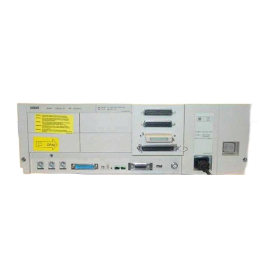
Step 3: Connecting the Console Terminal 1. Connect one end of the terminal cable to the modified modular jack (MMJ) port 3. This system will be shipped with a label covering ports 0 and 1. After port 3 is properly identified as the console port, the OPA0 arrow label may be removed. -
Page 9: Step 4: Connecting The Thinwire Terminator
Step 4: Connecting the ThinWire Terminator 1. Assemble the T-connector and the two terminators to form a ThinWire terminator. 2. Connect the ThinWire terminator to the system unit. Figure 1–3 ThinWire Termination MLO-009276 T-Connector Terminator ¡ 1–4 Installation Procedure... -
Page 10: Step 5: Connecting The Scsi Terminator
Step 5: Connecting the SCSI Terminator 1. Connect the SCSI terminator to the SCSI port. 2. Close the bail lock loops. Figure 1–4 Connecting the SCSI Terminator MLO-009696 SCSI Terminator Installation Procedure 1–5... -
Page 11: Step 6: Connecting The Dssi Terminator
Step 6: Connecting the DSSI Terminator Figure 1–5 Connecting the DSSI Terminator MLO-009697 DSSI Terminator 1–6 Installation Procedure... -
Page 12: Step 7: Connecting The Power Cord
Step 7: Connecting the Power Cord 1. Ensure that the on/off switch is in the off (O) position. 2. Connect the power cord to the system unit. 3. Connect the other end of the power cord to an isolated, grounded circuit. Figure 1–6 Power Cord Connection MLO-009277 On/Off Switch... -
Page 13: Step 8: Turning On The Console Terminal And System Unit
Step 8: Turning on the Console Terminal and System Unit 1. Turn on the console terminal. Wait until it completes its power-up test. (See the terminal documentation for more information.) 2. Check the terminal settings. See the VAX 4000 Model 100 Operator Information manual for the list of correct settings. -
Page 14: Step 9: Checking The Power-Up Test Results
Step 9: Checking the Power-Up Test Results The power-up test can take several minutes to complete, depending on the number of installed options and on which default settings you use. 1. If the power-up test results on the screen are similar to the results in Example 1–1, the system has passed the power-up test. - Page 15 If SIMM_OD is not present or not plugged in correctly, the system responds with a display similar to the following example: Example 1–2 Unsuccessful Power-Up Test Screen KA52-A V1.1, VMB 2.14 Performing normal system tests. 72..71..70..69..68..67..66..65..64..63..62.. ? Test_Subtest_DC_88 Loop_Subtest=05 Err_Type=FF DE_NO_Memory_present.lis Vec=0000 Prev_Errs=0000 P1=E04EE04E...
-
Page 16: Step 10: Connecting The System To A Network
Step 10: Connecting the System to a Network If you want to connect the system to a network, see the VAX 4000 Model 100 Operator Information manual. Step 11: Connecting External Options to the System If you want to connect external options to the system, see the VAX 4000 Model 100 Operator Information manual. - Page 17 Reader’s Comments VAX 4000 Model 100 Installation Information EK–465AA–IN. A01 Your comments and suggestions help us improve the quality of our publications. Please rate the manual in the following categories: Excellent Good Fair Poor Accuracy (product works as described) Completeness (enough information) Clarity (easy to understand) Organization (structure of subject matter) Figures (useful)
- Page 18 IN THE UNITED STATES BUSINESS REPLY MAIL FIRST CLASS PERMIT NO. 33 MAYNARD MASS. POSTAGE WILL BE PAID BY ADDRESSEE DIGITAL EQUIPMENT CORPORATION INFORMATION DESIGN AND CONSULTING PKO3–1/D30 129 PARKER STREET MAYNARD, MA 01754–9975 Do Not Tear – Fold Here and Tape...
Need help?
Do you have a question about the VAX 4000 100 and is the answer not in the manual?
Questions and answers