
Subscribe to Our Youtube Channel
Related Manuals for Digi-Sense 20250-63


Summary of Contents for Digi-Sense 20250-63
- Page 1 User Manual AC/DC True RMS Clamp Meter with Bluetooth Mobile App and ® NIST-Traceable Calibration Model 20250-63 THE STANDARD IN PRECISION MEASUREMENT 1065DGMAN_20250-63_Rev1.indd 1 07/02/2019 10:31:06 AM...
- Page 2 Introduction The Digi-Sense AC/DC True RMS Clamp Meter with Bluetooth Connectivity (model 20250-63) allows you ® to transmit data directly to your Android or iOS ™ ® device using our free D/S Meter mobile app. Now you can view data at a safe distance from potentially...
-
Page 3: Double Insulation
Safety International Safety Symbols This symbol, adjacent to another symbol or terminal, indicates the user must refer to the manual for further information. This symbol, adjacent to a terminal, indicates that, under normal use, hazardous voltages may be present Double insulation SAFETY NOTES •... - Page 4 WARNINGS • Set rotary function switch to the appropriate position before measuring. • When measuring volts do not switch to current/ resistance modes. • Do not measure current on a circuit whose voltage exceeds 600 V. • When changing ranges always disconnect the test leads from the circuit under test.
- Page 5 • Connect the equipment into an outlet on a circuit dif- ferent from that to which the receiver is connected. • Consult the dealer or an experienced radio/TV technician for help. CAUTIONS • Improper use of this meter can cause damage, shock, injury or death.
-
Page 6: Key Features
Unpacking Check individual parts against the list of items below. If anything is missing or damaged, please contact your instrument supplier immediately. 1. Meter 2. Test leads 3. One type K temperature probe 4. One 9 V battery 5. Carrying case 6. -
Page 7: Meter Description
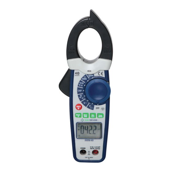
Meter Description 1. NCV test 2. Current clamp 3. Noncontact AC voltage indicator light 4. Clamp trigger 5. Rotary function switch 6. Data HOLD and Backlight button 7. PEAK and INRUSH button 8. REL and Hz% button 9. MODE select and Bluetooth button 10. -
Page 8: Display Layout
Display Layout HOLD Data Hold Minus sign Negative reading display 0 to 5999 Measurement display digits REL/ DCA Zero MAX/MIN Maximum/Minimum Auto Power-off AUTO Autorange mode DC/AC Direct Current / Alternating Current Low battery mV or V Milli-volts or Volts (Voltage) Ω... -
Page 9: Setup And Operation
Setup and Operation NOTE: Read and understand all Warning and Caution statements in this user manual prior to using this meter. Set the rotary function switch to the OFF position when the meter is not in use. AC/DC Current Measurements WARNING: Ensure that the test leads are disconnected from the meter before making current clamp measurements. -
Page 10: Dc Voltage Measurement
DC Voltage Measurement 1. Insert the black test lead into the negative COM terminal and the red test lead into the positive V Ω CAP Hz% Temp terminal. • 2. Set the rotary function switch to the V– position. 3. Connect the test leads in parallel to the circuit under test. 4. -
Page 11: Frequency Measurements
Frequency Measurements 1. Insert the black test lead banana plug into the negative COM jack and the red test lead banana plug into the V Ω • CAP Hz% Temp positive jack. 2. Set the rotary function switch to the V~ position. 3. -
Page 12: Continuity Measurements
Continuity Measurements 1. Insert the black test lead into the negative COM terminal and the red test lead into the V Ω CAP Hz% Temp positive • terminal. Ω 2. Set the rotary function switch the •))) position. 3. Use the MODE button to select continuity “• ”. -
Page 13: Noncontact Ac Voltage Measurements
Noncontact AC Voltage Measurements WARNING: Risk of Electrocution. Before use, always test the Voltage Detector on a known live circuit to verify proper operation. 1. Touch the probe tip to the hot conductor or insert into the hot side of the electrical outlet. -
Page 14: Data Hold/Backlight Button
PEAK/INRUSH Button Note: Only ACV functions can do the PEAK value measurement. 1. PEAK Key is the peak value measurement key that acts with trigger. 2. In ACV functions, press PEAK/INRUSH button to activate the detection of Maximum and Minimum peak AC Voltage values with a response time of 1 ms. -
Page 15: Max/Min Button
MAX/MIN Button 1. Press MAX/MIN key to measure the maximum and minimum values. This mode is activated on each measurement except for continuity test, diode test capacitance test, frequency test, and duty cycle test. 2. The MAX/MIN mode is disabled by holding the MAX/MIN button down for several seconds or by moving the rotary function switch. -
Page 16: Specifications
Specifications Accuracy Function Range Resolution (% of reading + digits) 60.00 A 10 mA +2.5% of rdg + 8 digits AC True RMS Current 600.0 A 100 mA +2.5% of rdg + 8 digits (Auto-ranging) 1000 A +2.8% of rdg + 8 digits Over-range protection: maximum input 1000 A Accuracy specified from 5% to 100% of the measuring range Frequency response: 50 Hz to 60 Hz True RMS... - Page 17 Accuracy Function Range Resolution (% of reading + digits) 600.0 Ω 0.1 Ω +1% of rdg + 4 digits 6.000 kΩ 1 Ω +1.5% of rdg + 2 digits 60.00 kΩ 10 Ω +1.5% of rdg + 2 digits Resistance (Auto-ranging) 600.0 kΩ...
-
Page 18: General Specifications
Accuracy Function Range Resolution (% of reading + digits) Duty Cycle 20.0% to 80.0% +1.2% of rdg + 10 digits Accuracy Function Range Resolution (% of reading + digits) –20 to 760°C 0.1/1°C +3% of rdg + 5°C Temperature –4 to 1400°F 0.1/1°F +3% of rdg + 9°F Sensor: Type K thermocouple... -
Page 19: Cleaning And Storage
Input Impedance 10 MΩ (VDC and VAC) True RMS (AAC and VAC) AC response Operating temperature 41 to 104°F (5 to 40°C) –4 to 140°F (–20 to 60°C) Storage temperature Operating humidity Max 80% up to 87°F (31°C) decreasing linearly to 50% at 104°F (40°C) <80% Storage humidity Operating altitude... - Page 20 It is recommended that Digi-Sense products are calibrated annually to ensure proper function and accurate measure- ments; however, your quality system or regulatory body may require more frequent calibrations. To schedule your recalibration, please contact InnoCal, an ISO 17025 calibration laboratory accredited by A2LA.
Need help?
Do you have a question about the 20250-63 and is the answer not in the manual?
Questions and answers