Table of Contents
Advertisement
Quick Links
C
P
C
P
OULTER
RO •
OULTER
RO •
P
C
P
C
ER
RO •
OULTER
RO •
OULTER
C
P
C
P
OULTER
RO •
OULTER
RO •
P
C
P
C
ER
RO •
OULTER
RO •
OULTER
C
P
C
P
OULTER
RO •
OULTER
RO •
P
C
P
C
ER
RO •
OULTER
RO •
OULTER
C
P
C
P
OULTER
RO •
OULTER
RO •
P
C
P
C
ER
RO •
OULTER
RO •
OULTER
C
P
C
P
OULTER
RO •
OULTER
RO •
P
C
P
C
ER
RO •
OULTER
RO •
OULTER
C
P
C
P
OULTER
RO •
OULTER
RO •
P
C
P
C
ER
RO •
OULTER
RO •
OULTER
C
P
C
P
OULTER
RO •
OULTER
RO •
P
C
P
C
ER
RO •
OULTER
RO •
OULTER
C
P
C
P
OULTER
RO •
OULTER
RO •
P
C
P
C
ER
RO •
OULTER
RO •
OULTER
C
P
C
P
OULTER
RO •
OULTER
RO •
P
C
P
C
ER
RO •
OULTER
RO •
OULTER
C
P
C
P
OULTER
RO •
OULTER
RO •
P
C
P
C
ER
RO •
OULTER
RO •
OULTER
C
P
C
P
OULTER
RO •
OULTER
RO •
P
C
P
C
ER
RO •
OULTER
RO •
OULTER
C
P
C
P
OULTER
RO •
OULTER
RO •
P
C
P
C
ER
RO •
OULTER
RO •
OULTER
C
P
C
P
OULTER
RO •
OULTER
RO •
P
C
P
C
ER
RO •
OULTER
RO •
OULTER
C
P
C
P
OULTER
RO •
OULTER
RO •
P
C
P
C
ER
RO •
OULTER
RO •
OULTER
C
P
C
P
OULTER
RO •
OULTER
RO •
P
C
P
C
ER
RO •
OULTER
RO •
OULTER
C
P
C
P
OULTER
RO •
OULTER
RO •
P
C
P
C
ER
RO •
OULTER
RO •
OULTER
C
P
C
P
OULTER
RO •
OULTER
RO •
P
C
P
C
ER
RO •
OULTER
RO •
OULTER
C
P
C
P
OULTER
RO •
OULTER
RO •
P
C
P
C
ER
RO •
OULTER
RO •
OULTER
C
P
C
P
OULTER
RO •
OULTER
RO •
P
C
P
C
ER
RO •
OULTER
RO •
OULTER
C
P
C
P
OULTER
RO •
OULTER
RO
P
C
P
• C
RO •
OULTER
RO
OULT
C
P
C
P
OULTER
RO •
OULTER
RO
C
P
C
P
• C
RO •
OULTER
RO
OULT
C
P
C
P
OULTER
RO •
OULTER
RO
P
C
P
• C
RO •
OULTER
RO
OULT
C
P
C
P
OULTER
RO •
OULTER
RO
P
C
P
• C
RO •
OULTER
RO
OULT
C
P
C
P
OULTER
RO •
OULTER
RO
P
C
P
• C
RO •
OULTER
RO
OULT
C
P
C
P
OULTER
RO •
OULTER
RO
and Operators
P
C
P
• C
RO •
OULTER
RO
OULT
C
P
C
P
OULTER
RO •
OULTER
RO
Manual
P
C
P
• C
RO •
OULTER
RO
OULT
C
P
C
P
OULTER
RO •
OULTER
RO
P
C
P
• C
RO •
OULTER
RO
OULT
C
P
C
P
OULTER
RO •
OULTER
RO
P
C
P
• C
RO •
OULTER
RO
OULT
C
P
C
P
OULTER
RO •
OULTER
RO
P
C
P
• C
RO •
OULTER
RO
OULT
C
P
C
P
OULTER
RO •
OULTER
RO
P
C
P
• C
RO •
OULTER
RO
OULT
C
P
C
P
OULTER
RO •
OULTER
RO
P
C
P
• C
RO •
OULTER
RO
OULT
C
P
C
P
OULTER
RO •
OULTER
RO
P
C
P
• C
RO •
OULTER
RO
OULT
C
P
C
P
OULTER
RO •
OULTER
RO
P
C
P
• C
RO •
OULTER
RO
OULT
C
P
C
P
OULTER
RO •
OULTER
RO
P
C
P
• C
RO •
OULTER
RO
OULT
C
P
C
P
OULTER
RO •
OULTER
RO
P
C
P
• C
RO •
OULTER
RO
OULT
C
P
C
P
OULTER
RO •
OULTER
RO
P
C
P
• C
RO •
OULTER
RO
OULT
C
P
C
P
OULTER
RO •
OULTER
RO
P
C
P
• C
RO •
OULTER
RO
OULT
Manual Number 08000000
C
P
C
P
OULTER
RO •
OULTER
RO
Rev. 3-1-13
P
C
P
• C
RO •
OULTER
RO
OULT
OULTER
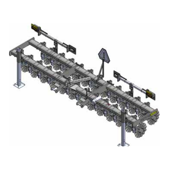
15' Rigid Frame
20' Rigid Frame
30' Folding Frame
P
RO
TM
Advertisement
Table of Contents

Related Manuals for BLU-JET COULTERPRO Series


Summary of Contents for BLU-JET COULTERPRO Series
- Page 1 OULTER RO • OULTER RO • OULTER RO • OULTER • C RO • OULTER RO • OULTER RO • OULTER OULT OULTER RO • OULTER RO • OULTER RO • OULTER • C RO • OULTER RO • OULTER RO •...
-
Page 3: Table Of Contents
Manual Number: 08000000 CoulterPro Table of Contents Rev. 3-1-13 Introduction............................Delivery..............................To The Owner............................Warranty.............................. Safety..............................Operating Instructions........................Storage..............................15’ CoulterPro, Coulter Bundles, and Row Spacings..............Frame, CoulterPro 15’ (80200015)..................... Light Kit 15’ Rigid Frame (41000040)....................31 20’ CoulterPro, Coulter Bunbles, and Row Spacings..............Frame, CoulterPro 15’... -
Page 4: Introduction
Environmental, Safety, Quality, Production and Engineering keep our firm at the cutting edge of technology. We hope your BLU-JET equipment will give you years of service. ead this manual carefully. It will instruct you on how to operate and service your machine safely and correctly. Failure to do so could result in personal injury and/or equipment damage. - Page 5 Introduction General Information: The BLU-JET CoulterPro unit is one of the most versatile machines you can own. Using the Super 1200 Coulter, the CoulterPro is designed to chop and size residue and lightly till the soil. Available in four working widths from 15’...
-
Page 6: Delivery
Dealer Checklist o The Dealer: Inspect the implement thoroughly after assembly to be certain it is functioning properly before delivering it to the customer. The following checklist is a reminder of points to cover. Check off each item as it is found satisfactory or after proper adjustment is made. -
Page 7: To The Owner
To The Owner hank you for your recent purchase of a new BLU-JET implement. The primary objective of Thurston Manufacturing Company is to build and provide you with a quality product. However, in the event that a problem does occur, it is imperative that your warranty registration is on file in order to accurately respond to your specific service circumstances. -
Page 8: Warranty
Warranty begins from date of delivery to the original purchaser and applies to all new BLU-JET products that have not been altered and are being used for the intended purpose. Negligence, abuse or modification of equipment manufactured by or purchased and resold by Thurston Manufacturing Company will void this warranty. -
Page 9: Safety
Safety RECOGNIZE SAFETY INFORMATION • This is the safety-alert symbol. When you see his symbol on your machine or in this manual, be alert to the potential for personal injury. Follow recommended precautions and safe operating practices. FOLLOW SAFETY INSTRUCTIONS •... - Page 10 Safety Observe Safety Signs Rigid Frame AP 2483-8-98 AP 2914 Folding Frame AP 2234-7-98...
-
Page 11: Operating Instructions
Operating Instruction Task Procedures Illustrations Lubricating 1. Unfold wings and grease wing hinges daily. wing hinge NOTE: Grease all zerks daily. Coulter 2. Grease all coulter arm pivots. pivot shaft lubrication Coulter 3. The plug on the coulter hub can be removed. A zerk can be installed. -
Page 12: Storage
Operating Instruction Task Procedures Illustrations Wing flex Flex spacers NOTE: Wing flex spacers in the out spacers out position position. Wing can float 2 degrees down 3 1/4” below level a range of approximately 35” (30 ft. toolbar) This spacer position should be used for mechanical or hydraulic wing lockdown. Wing flex spacers positioned to the inside. Wings can float from 7-1/2”... -
Page 13: 15' Coulterpro, Coulter Bundles, And Row Spacings
80000011 CoulterPro 15’, 25 x 7” Spacing 80000011 CoulterPro 15’, 25 x 7” Spacing... - Page 14 80200019 Coulter Bundle, Drill Till 25 x 7” Spacing AM4773 4 PLACES 80200019 Coulter Bundle, Drill Till 25 x 7” Spacing...
- Page 15 80000011 CoulterPro 15’, 25 x 7” Spacing...
- Page 16 80000011 CoulterPro 15’, 25 X 7 and 26 X 7 CoulterPro 80000011 15’ Drill Till 25 X 7 CoulterPro 80000011 15’ Drill Till 26 X 7...
- Page 17 80000011 CoulterPro 15’, 26 x 7” Spacing CoulterPro 80000011 15’ Drill Till 26 X 7...
- Page 18 80200011 Coulter Bundle Drill Till, 26 X 7” Spacing AM4773 AM4774 80200011 Coulter Bundle Drill Till 26 X 7” Spacing...
- Page 19 80000011 CoulterPro 15’, 26 x 7” Spacing...
- Page 20 80000012 CoulterPro 15’, 24 x 7.5” Spacing...
- Page 21 80000012 CoulterPro 15’, 24 x 7.5” Spacing CoulterPro 80000012 15’ Drill Till 24 X 7.5”...
- Page 22 80200010 Coulter Bundle Drill Till, 24 X 7.5” Spacing AM4773 80200010 Coulter Bundle Drill Till 24 X 7.5” Spacing...
- Page 23 80000012 CoulterPro 15’, 24 x 7.5” Spacing...
- Page 24 80000013 CoulterPro 15’, 22 x 8” Spacing...
- Page 25 80000013 CoulterPro 15’, 22 x 8” Spacing CoulterPro 80000013 15’ Drill Till 22 X 8”...
- Page 26 80200012 Coulter Bundle Drill Till, 22 X 8” Spacing AM4774 AM4773 80200012 Coulter Bundle Drill Till 22 X 8” Spacing...
- Page 27 80000013 CoulterPro 15’, 22 x 8” Spacing...
- Page 28 80000014 CoulterPro 15’, 18 x 10” Spacing...
- Page 29 80000014 CoulterPro 15’, 18 x 10” Spacing CoulterPro 80000014 15’ Drill Till 18 X 10”...
- Page 30 80200014 Coulter Bundle Drill Till, 18 X 10” Spacing AM4774 AM4773 80200014 Coulter Bundle Drill Till 18 X 10” Spacing...
- Page 31 80000014 CoulterPro 15’, 18 x 10” Spacing...
-
Page 32: Frame, Coulterpro 15' (80200015)
80200015 CoulterPro Frame 15’ 80200015 CoulterPro Frame 15’... -
Page 33: Light Kit 15' Rigid Frame (41000040)
41000040 Light Kit, Rigid CoulterPro 41000040 Light Kit Rigid CoulterPro... -
Page 34: 20' Coulterpro, Coulter Bunbles, And Row Spacings
80000015 CoulterPro 20’, 32 x 7.5” Spacing Bolt-on Wings Rigid Frame... - Page 35 80000015 CoulterPro 20’, 32 x 7.5” Spacing CoulterPro 80000015, 20’ Drill Till 32 X 7.5” Bolt on Wings CoulterPro 80000015, 20’ Drill Till 32 X 7.5” Rigid Frame...
- Page 36 80200022 Coulter Bundle Drill Till, 32 X 7.5” Spacing AM4774 80200022 Coulter Bundle Drill Till 32 X 7.5” Spacing...
- Page 37 80000015 CoulterPro 20’, 32 x 7.5” Spacing...
- Page 38 80000016 CoulterPro 20’, 34 x 7” Spacing Bolt-on Wings Rigid Frame...
- Page 39 80000016 CoulterPro 20’, 34 x 7” Spacing CoulterPro 80000016, 20’ Drill Till 34 X 7” Bolt on Wings CoulterPro 80000016, 20’ Drill Till 34 X 7” Rigid Frame...
- Page 40 80200033 Coulter Bundle Drill Till, 34 X 7” Spacing AM4774 AM4773 80200033 Coulter Bundle Drill Till 34 X 7” Spacing...
- Page 41 80000016 CoulterPro 20’, 34 x 7” Spacing...
- Page 42 80000017 CoulterPro 20’, 30 x 8” Spacing Bolt-on Wings Rigid Frame...
- Page 43 80000017 CoulterPro 20’, 30 x 8” Spacing CoulterPro 80000017, 20’ Drill Till 30 X 8” Bolt on Wings CoulterPro 80000017, 20’ Drill Till 30 X 8” Rigid Frame...
- Page 44 80200023 Coulter Bundle Drill Till, 30 X 8” Spacing AM4774 AM4773 80200023 Coulter Bundle Drill Till 30 X 8” Spacing...
- Page 45 80000017 CoulterPro 20’, 30 x 8” Spacing...
- Page 46 80000018 CoulterPro 20’, 24 x 10” Spacing Bolt-on Wings Rigid Frame...
- Page 47 80000018 CoulterPro 20’, 24 x 10” Spacing CoulterPro 80000018, 20’ Drill Till 24 X 10” Bolt on Wings CoulterPro 80000018, 20’ Drill Till 24 X 10” Rigid Frame...
- Page 48 80200024 Coulter Bundle Drill Till, 24 X 10” Spacing AM4774 AM4773 80200024 Coulter Bundle Drill Till 24 X 10” Spacing...
- Page 49 80000018 CoulterPro 20’, 24 x 10” Spacing...
-
Page 50: Frame, Coulterpro 15' (80200015)
80200015 CoulterPro Frame 15’ 80200015 CoulterPro Frame 15’... -
Page 51: 15' - 20' Bolt-On Wing Kit (80000000)
80000000 CoulterPro Wing Kit 15’-20’ 80000000 CoulterPro Wing Kit 15’-20’... -
Page 52: Frame Coulterpro 20' (80200020)
80200020 CoulterPro Frame 20’ 80200020 CoulterPro Frame 20’... -
Page 53: Light Kit 20' Rigid Frame (41000040)
41000040 Light Kit, Rigid CoulterPro 41000040 Light Kit Rigid CoulterPro... -
Page 54: 24' Folding Coulterpro, Coulter Bundles, And Row Spacings
80100013 CoulterPro 24’ Folding, 40 x 7” Spacing... - Page 55 80100013 CoulterPro 24’ Folding, 40 x 7” Spacing CoulterPro 80100013 24’ Folding Drill Till 40 X 7”...
- Page 56 80210035 Coulter Bundle Drill Till, 40 X 7” Spacing AM4779 AM4773 X 13 AM4774 80210035 Coulter Bundle Drill Till 40 X 7” Spacing...
- Page 57 80100013 CoulterPro 24’ Folding, 40 x 7” Spacing...
- Page 58 80100014 CoulterPro 24’ Folding, 38 x 7.5” Spacing...
- Page 59 80100014 CoulterPro 24’ Folding, 38 x 7.5” Spacing CoulterPro 80100014 24’ Folding Drill Till 38 X 7.5”...
- Page 60 80210036 Coulter Bundle Drill Till, 38 X 7.5” Spacing AM2719 AM4779 AM4773 X 13 AM4774 80210036 Coulter Bundle Drill Till 38 X 7.5” Spacing...
- Page 61 80100014 CoulterPro 24’ Folding, 38 x 7.5” Spacing...
- Page 62 80100015 CoulterPro 24’ Folding, 34 x 8” Spacing...
- Page 63 80100015 CoulterPro 24’ Folding, 34 x 8” Spacing CoulterPro 80100015 24’ Folding Drill Till 34 X 8”...
- Page 64 80210038 Coulter Bundle Drill Till, 34 X 8” Spacing AM4773 X 7 AM4774 80210038 Coulter Bundle Drill Till 34 X 8” Spacing...
- Page 65 80100015 CoulterPro 24’ Folding, 34 x 8” Spacing...
- Page 66 80100016 CoulterPro 24’ Folding, 35 x 8” Spacing...
- Page 67 80100016 CoulterPro 24’ Folding, 35 x 8” Spacing CoulterPro 80100016 24’ Folding Drill Till 35 X 8”...
- Page 68 80210037 Coulter Bundle Drill Till, 35 X 8” Spacing AM4773 X 8 AM4774 80210037 Coulter Bundle Drill Till 35 X 8” Spacing...
- Page 69 80100016 CoulterPro 24’ Folding, 35 x 8” Spacing...
-
Page 70: Frame, Coulterpro 24' Folding (80210047)
80210047 CoulterPro Frame 24’, Folding 80210047 CoulterPro Frame 24’, Folding... - Page 71 80210047 CoulterPro Frame 24’, Folding...
-
Page 72: Hydraulic Fold 24' Coulterpro (80210034)
80210034 Hydraulic Fold 24’ CoulterPro... -
Page 73: Light Kit 24' Folding Frame (41000038)
41000038 Light Kit, Folding CoulterPro 41000038 Light Kit Folding CoulterPro... -
Page 74: 30' Folding Coulterpro, Coulter Bundles, And Row Spacings
80100005 CoulterPro 30’ Folding, 50 x 7” Spacing... - Page 75 80100005 CoulterPro 30’ Folding, 50 x 7” Spacing CoulterPro 80100005 30’ Folding Drill Till 50 X 7”...
- Page 76 80210050 Coulter Bundle Drill Till, 50 X 7” Spacing AM4779 AM4773 X 13 AM4774 80210050 Coulter Bundle Drill Till 50 X 7” Spacing...
- Page 77 80100005 CoulterPro 30’ Folding, 50 x 7” Spacing...
- Page 78 80100006 CoulterPro 30’ Folding, 48 x 7.5” Spacing...
- Page 79 80100006 CoulterPro 30’ Folding, 48 x 7.5” Spacing CoulterPro 80100006 30’ Folding Drill Till 48 X 7.5”...
- Page 80 80210051 Coulter Bundle Drill Till, 48 X 7.5” Spacing AM4779 AM2719 AM4773 X 12 AM4774 80210051 Coulter Bundle Drill Till 48 X 7.5” Spacing...
- Page 81 80100006 CoulterPro 30’ Folding, 48 x 7.5” Spacing...
- Page 82 80100007 CoulterPro 30’ Folding, 44 x 8” Spacing...
- Page 83 80100007 CoulterPro 30’ Folding, 44 x 8” Spacing CoulterPro 80100007 30’ Folding Drill Till 44 X 8”...
- Page 84 80210053 Coulter Bundle Drill Till, 44 X 8” Spacing AM4779 AM4773 X 7 AM4774 80210053 Coulter Bundle Drill Till 44 X 8” Spacing...
- Page 85 80100007 CoulterPro 30’ Folding, 44 x 8” Spacing...
- Page 86 80100008 CoulterPro 30’ Folding, 45 x 8” Spacing...
- Page 87 80100008 CoulterPro 30’ Folding, 45 x 8” Spacing CoulterPro 80100008 30’ Folding Drill Till 45 X 8”...
- Page 88 80210052 Coulter Bundle Drill Till, 45 X 8” Spacing AM4773 X 8 AM4774 80210052 Coulter Bundle Drill Till 45 X 8” Spacing...
- Page 89 80100008 CoulterPro 30’ Folding, 45 x 8” Spacing...
-
Page 90: Frame, Coulterpro 30' Folding (80210048)
80210048 CoulterPro Frame 30’, Folding 80210048 CoulterPro Frame 30’, Folding... - Page 91 80210048 CoulterPro Frame 30’, Folding...
-
Page 92: Hydraulic Fold 30' Coulerpro (80210049)
80210049 Hydraulic Fold 30’ CoulterPro... -
Page 93: Light Kit 30' Folding Frame (41000038)
41000038 Light Kit, Folding CoulterPro 41000038 Light Kit Folding CoulterPro... -
Page 94: Flatback Coulter Mounts
Flatback Mounts AM4772 Bracket, Flatback 4 x 6, Centered with Hardware AM4773 Bracket, Flatback Off Centered, 4 x 6 with Hardware... - Page 95 Flatback Mounts AM4774 Bracket, Flatback, 4 x 6, Offset with Hardware AM4779 Bracket, Flatback Offset, 4 x 6, Offset with Hardware...
-
Page 96: Pull Pin Kit (80210201)
Universal Mounts and Pull Pin Kit (80210201) AM2719 Bracket, Universal Coulter 80210201 Pull Pin Kit Cat III... -
Page 97: Super 1200 Flex Coulter And Shank Parts
Coulter and Shank Parts AM2799 AM2799 Assembly, Coulter Arm With Hub and Knee Casting HD Coulter, 12” Shank, 1 Row... -
Page 98: Manual Holder Aam2639
AAM2639 Manual Holder & AAM2442 Park Stand AAM2639 Manual Holder W/6 x 4 Mounting AAM2442 Park Stank Assembly... -
Page 99: Stabilizer 9400/Coulterpro, Aam2858
AAM2858 Stabilizer Assembly 9400/CoulterPro AAM2858 Stabilizer Assembly 9400/CoulterPro... -
Page 100: Hydraulic Cylinders And Parts
Hydraulic Cylinders And Parts MFG # Bore/ TMC # Stroke Repair Kit Clevis Butt Gland Piston SAE-33524A 3-1/2” x 24” PMCK-SAE-33600 100000577 141700023 081700255 071700174 DP4247 DP4309 DP3996 DP4319 DP4325 DP4327 SAE-33024 3” X 24” PMCK-SAE-33000 100000423 141500043 081500323 071500244 DP4246 DP4308 DP4116... -
Page 101: Assembly
Tie-rod Cylinder Disassembly - Assembly Procedure With cylinder removed from machine, clean, drained of oil and fully retracted, proceed as follows: Disassembly: 1. Secure cylinder in vice or other method to prevent rotation. With the immediate area clean of dirt so parts can be laid out. 2. -
Page 102: Assembly
Assembly (Rigid Frame) Task Procedures Illustrations Positioning Position rigid CoulterPro frame on sturdy stands, about main frame 35” high on hard level surface. on stands NOTE: Consult row spacing before positioning stands. Position stands to avoid interference with row assemblies. DANGER Secure frame to... -
Page 103: 15' - 20' Wing Kit (80000000)
Assembly (80000000 Wing Kit 15’-20’) 80000000 CoulterPro Wing Kit 15’-20’ To convert 15’ toolbar to a 20’ toolbar, attach (2) AM4744 wing extensions to main frame with hardware provided in bundle 8000000 Bolt-on Wing Kit. -
Page 104: Folding Frame
Assembly (Folding CoulterPro) Task Procedures Illustrations Main frame Position folding CoulterPro frame on sturdy stands, about 35” high on hard level surface. Installation Install wing flex spacers (a) AM4735 Flex spacers (AM4735) on frame with of wing flex out position (BP3041) 1/2” x 2” hex cap spacers screws and (c) (BP3244) - Page 105 Assembly (Folding CoulterPro) Task Procedures Illustrations Square head of pin to the Attaching the outside of weldment. wing BP3610 Secure pin with (e) (BP3096) 3/8” x 2-1/2” hex cap screws (f) (BP3003) 3/8” hex lock nuts. BP3096 BP3003 Tractor side Place wing on sturdy stands.
-
Page 106: Park Stand Assembly, Aam2442
Assembly (AAM2442 Park Stand) Task Procedures Illustrations Park stand AAM2442 Parking Stand Assembly Parts Consult row spacing pages NOTE: for open location for park stand If main mount on mainframe as far out frame stands as possible. are high enough Insert (2) (AM4682) park stand... -
Page 107: Pull Pin Kit, Cat Iii, 80210201
Assembly (80210201 CoulterPro Pull Pin Kit Cat III) Task Procedures Illustrations Pull pin kits Bundle Number 80210201 Install pull pin kits to main frame Rocker plate Install (a) (AM4063) rocker plate with (b) (BP3509) 1-1/4” installation AM4063 x 4-23/32” CAT. III pin and folding securewith (c) (BP3517) -
Page 108: Flatback Mounts
Assembly (Mounting Flatbacks) Task Procedures Illustrations Mounting 1. Consult row spacing pages coulter and mark bracket locations. flatbacks 2. Mounting (a) (AM4772) 4 x 6 flatback, centered and (b) (AM4779) 4 x 6 flatback, offset to frame. 3. Place (c) (BP3331) 5/8 x 4”W x 7-3/4”L u-bolts over tube and install flatback. Center coulter BP3331 shank slot on the bracket with... -
Page 109: Super 1200 Flex Coulter
Coulter Assembly Task Procedures Illustrations 1. Remove hex cap screws from Preparing AP2799 (a) (AM2799) coulter arm coulters with hub and knee casting assembly. mounting AP2840 2. Place coulter blade on NOTE: coulter assembly and replace Smooth hex cap screws. blade shown. - Page 110 Assembly (Mounting Coulters) Task Procedures Illustrations Mounting Insert coulter shank assembly BP3042 into the mounting. coulters BP3043 Insert the (a) (BP3229) 1/2”- 13 x 2-1/2” carriage bolt into top hole of bracket. Push coulter shank assembly back into the bracket and insert the bottom carriage bolt.
-
Page 111: Manual Holder Aam2639
Assembly (AAM2639 Manual Holder W/6 x 4 Mounting) Task Procedures Illustrations AAM2639 Manual Holder NOTE: Consult spacing pages for manual holder location AAM2639 Manual Holder W/6 x 4 Mounting 1. Mount (3) (AP4254) manual holder (1) (AM7640) manual holder bracket with (4) (BP3006) 3/8”... - Page 112 Assembly (Hydraulics) Task Procedures Illustrations Mounting Left-hand wing cylinders NOTE: Left-hand right-hand as viewed from the rear. Install wing cylinders to main frame cylinder weldment. (Consult hydraulic diagram) Secure with cylinder pins and cotter keys. Install (7) (DP4551) adapter with restrictor in the top port of each cylinder.
-
Page 113: Hydraulics
Assembly (Hydraulics) Task Procedures Illustrations Connecting Connect the hydraulic hoses hydraulic to the tractor remote couplers. The 1/4” hoses supply oil to hoses the wing cylinders. Mark CAUTION CAUTION: 1/4” hose pairs with paint or Always tape. Mark hoses so that hook tool they are plugged in correctly bar to tractor... -
Page 114: Light Kit Rigid Frame (41000040)
41000040 Light Kit, Rigid CoulterPro NOTE: Consult spacing pages bracket locations... - Page 115 Assembly (41000040 Light Kit, Rigid Frame) Task Procedures Illustrations Mounting light kit brackets Consult row spacing pages BP3214 AM3408 for bracket locations. Mount (a) (AM3408) mounting plate light post T to frame with CP2660 (b) (BP3214) 3/8” x 4”W x 7”L u-bolts.
- Page 116 Assembly (41000040 Light Kit, Rigid Frame) Task Procedures Illustrations Align hole in (g) (AM3409) Mounting light tube bracket, 3’5-7/8” AM3409 light kit with hole in plate. Tighten brackets plate hex nuts. Secure tube with (e) (BP3736) 3/8” x 2”W CP2660 x 3”L u-bolts and (c) (CP2660) 3/8”...
- Page 117 Assembly (41000040 Light Kit, Rigid Frame) Task Procedures Illustrations Attach two (i) (AM3421) side Mounting CP2660 mount light brackets to mounts light kit with (j) (BP3006) 3/8” x 1” hex AM3421 brackets cap screws and (c) (CP2660) 3/8” hex lock nuts. Install NOTE: BP3006 (AM3415)
- Page 118 Assembly (41000040 Light Kit, Rigid Frame) Task Procedures Illustrations Installing Red and AP3549 Amber AP3551 lamps Amber NOTE: AP4415 Left-hand right-hand as viewed from the rear. AP4415 Amber Left-hand from the rear Insert (m) (AP3551) model CP2660 Amber 60 oval grommets into Amber mountings.
- Page 119 Assembly (41000040 Light Kit, Rigid Frame) Task Procedures Illustrations Installing reflectors Attach (s) (AP2548) 2 x 9 Red reflectors below Red and Amber lights. Attach (t) (AP2551) 2 x 9 Red-Orange reflectors above Red and Amber lights. AP2548 Attach (u) (AP2547) 2 x 9 Yellow reflectors above AP2551 Amber lights and on...
- Page 120 Assembly (41000040 Light Kit, Rigid Frame) Task Procedures Illustrations AP3153 AP3142 Attach (b) (AP3142) 10’ main 5-wire, 7 pin electrical harness (a) (AP3153) 2 post, 5 wire electrical harness. Extend to dust cap. Cable tie wires to AP3142 tubes and frame.
-
Page 121: Light Kit Folding Frame (41000038)
41000038 Light Kit, Folding CoulterPro, StripTill NOTE: Consult spacing pages bracket locations... -
Page 122: Folding Frame
Assembly (41000038 Light Kit, Folding Frame) Task Procedures Illustrations Mounting light kit brackets Consult row spacing pages for bracket locations. CP2660 Mount (a) (AM3427) light AM3427 bracket, 16”, 4” mounting on main frame rear wing weldment area with (BP3214) 3/8” x 4”W x 7”L u-bolts. - Page 123 Assembly (41000038 Light Kit, Folding Frame) Task Procedures Illustrations Position (i) (AM3409) light Mounting CP2660 Wing Side tube bracket, 3’ 5-7/8”, 17” light kit 17” from the center of mounting brackets AM3409 plate to the wing side. Tighten plate hex nuts. Secure tube with (g) (BP3736) 3/8”...
- Page 124 Assembly (41000038 Light Kit, Folding Frame Task Procedures Illustrations Attach two (k) (AM3421) side CP2660 AM3421 Mounting mount light brackets to mounts light kit with (l) (BP3006) 3/8” x 1” hex brackets cap screws and (c) (CP2660) BP3006 3/8” hex lock nuts. Install NOTE: (AM3415) front light bracket...
- Page 125 Assembly (41000038 Light Kit, Folding Frame Task Procedures Illustrations Installing Red and Amber Amber AP4415 AP3551 lamps NOTE: Left-hand right-hand as viewed from the rear. AP3549 AP4415 Amber Insert (o) (AP3551) model Amber 60 oval grommets into Amber mountings. CP2660 Insert (p) (AP3549) lamp into grommet.
- Page 126 Assembly (41000038 Light Kit, Folding Frame) Task Procedures Illustrations Installing reflectors Attach (u) (AP2548) 2 x 9 Red reflectors below Red and Amber lights. Attach (v) (AP2551) 2 x 9 Red-Orange reflectors above Red and Amber lights. AP2551 Attach (w) (AP2547) 2 x 9 Yellow reflectors above Amber lights and on rear main frame plate.
- Page 127 Assembly (41000038 Light Kit, Folding Frame Task Procedures Illustrations AP3153 AP3142 Attach (b) (AP3142) 10’ main 5-wire, 7 pin electrical harness (a) (AP3153) 2 post, 5 wire electrical harness. Extend to dust cap. Cable tie wires to AP3142 tubes and frame.
-
Page 128: Decals
Actual Size 4” x 22” Color: Reflex Blue and Clear Coat On White FB5000 White Vinyl AP 2230 Decal, CoulterPro, 3-1/4” x 14” AP 2215 Decal, BLU-JET, 3 x 8 AP 2231 Decal, FEMA, 2-1/2” x 1-1/2” AP 2483 Decal, Danger, Falling From Equipment... - Page 129 Color: Reflex Blue and Clear Coat On White FB5000 White Vinyl Qty. 3,000 AP 2230 Decal, CoulterPro, 3-1/4” x 14” AP 2215 Decal, BLU-JET, 3 x 8 AP 2231 Decal, FEMA, 2-1/2” x 1-1/2” AP 2234 Decal, Danger Stand Clear Falling Wing AP 2483...
-
Page 130: Specifications
Specifications Tractor Attachment..3 Point Frames: Double 4” x 6” x 3/8: 26” Rank Weight......15’ Frame: 1198 lbs. Roller: 1098 lbs. Bolt-on Wings: 365 lbs. 20’ Frame: 1436 lbs. Roller: 1600 lbs. 24’ Frame: 2685 lbs. Roller: 1730 lbs. 30’ Frame: 3015 lbs. Roller: 2270 lbs. Coulter with blade, bracket, and hardware: 81 lbs. -
Page 131: Torque Specifications
Torque Specifications SAE FASTENER TORQUE CHART STAN NOTE: Use these torque's, unless special torque's are specified. Values are for UNC and UNF thread fasteners, plated or HYDRAU unplated, as received from supplier. Fasteners can be dry or lubricated with normal engine oil. Values do not apply if O-ring b graphite, moly-disulphide or other extreme pressure lubricant is used. -
Page 132: Stabilizer Assembly (Aam2858)
AAM2858 Stabilizer Assembly 9400/CoulterPro AAM2858 Stabilizer Assembly 9400/CoulterPro... - Page 133 AAM2858 Stabilizer Assembly 9400/CoulterPro Task Procedures Illustrations CoulterPro Center (2) (AM4897) stabilizer Stabilizer on back bar of CoulterPro frame. Secure to frame with four (6) (BP3208) 3/4” x 6”W x 5-3/4”L u-bolts, eight (BP3035) 3/4” lock washers and eight (4) (BP3034) 3/4”...
-
Page 134: Rolling Harrow 15
Optional Rolling Harrow 70210543 15’... - Page 135 Optional Rolling Harrow 70210543 15’...
-
Page 136: Rolling Harrow 20
Optional Rolling Harrow 70210544 20’... - Page 137 Optional Rolling Harrow 70210544 20’...
-
Page 138: Rolling Harrow 24
Optional Rolling Harrow 70210545 24’... - Page 139 Optional Rolling Harrow 70210545 24’...
-
Page 140: Rolling Harrow 30
Optional Rolling Harrow 70210546 30’... - Page 141 Optional Rolling Harrow 70210546 30’...
-
Page 142: Torsion Arm Basket Aam2876 45
AAM2876 45” Basket With Torsion Arm and Hardware... -
Page 143: Torsion Arm Basket Aam2878 75
AAM2878 75” Basket With Torsion Arm and Hardware... -
Page 144: Torsion Arm Basket Aam2879 90
AAM2879 90” Basket With Torsion Arm and Hardware... -
Page 145: Offset Brackets
Offset Brackets and Hardware... -
Page 146: Rolling Harrow Assembly
(Assembly) Optional Rolling Harrow Task Procedures Illustrations Mounting Harrow brackets BP3407 BP3035 BP3034 NOTE: Consult spacing pages for required brackets locations Consult row spacing pages for required offset brackets and locations. Mount offset bracket on frame rear with (b) (BP3407) BP3034 AM5124 3/4”... - Page 147 (Assembly) Optional Rolling Harrow Task Procedures Illustrations Mounting Rolling Harrow Mount (a) (AM5428) harrow BP3215 AM5428 slide linkage to with (BM3543) 1” x 4-5/16” double AP2407 grooved pin. Secrue pin with (c) (BP3215) 1-1/2” OD x 1” ID 14 GA machinery BM3543 bushings and (d) (AP2407)
- Page 148 (Assembly) Optional Rolling Harrow Task Procedures Illustrations Mounting Torsion Spring Baskets BP3012 BP3017 BP3016 Place (a) (AP2144) HCFT205-16 bearings on ends of basket. Position basket mounting arm over bearing and secure bearings and basket to arms with (BP3012) 7/16” x 1-1/2” hex cap screws, (e) (BP3017) 7/16”...
- Page 149 (Assembly) Optional Rolling Harrow Task Procedures Illustrations Mounting Light Kit AM3049 CP2660 NOTE: Light Kit mounts must be BP3736 relocated to rear of harrow mount arms on folding models Mount (a) (AM3409) light bracket to plate on rear of harrow mount using NOTE: (BP3736) 3/8”-16 x 2W x 3L...
- Page 150 Notes...
Need help?
Do you have a question about the COULTERPRO Series and is the answer not in the manual?
Questions and answers