Table of Contents
Advertisement
Quick Links
S
T
ll • S
T
ll • S
ub
iller
ub
iller
ll • S
T
ll • S
ller
ub
iller
ub
S
T
ll • S
T
ll • S
ub
iller
ub
iller
ll • S
T
ll • S
ller
ub
iller
ub
S
T
ll • S
T
ll • S
ub
iller
ub
iller
ll • S
T
ll • S
ller
ub
iller
ub
S
T
ll • S
T
ll • S
ub
iller
ub
iller
ll • S
T
ll • S
ller
ub
iller
ub
S
T
ll • S
T
ll • S
ub
iller
ub
iller
ll • S
T
ll • S
ller
ub
iller
ub
S
T
ll • S
T
ll • S
ub
iller
ub
iller
ll • S
T
ll • S
ller
ub
iller
ub
S
T
ll • S
T
ll • S
ub
iller
ub
iller
ll • S
T
ll • S
ller
ub
iller
ub
S
T
ll • S
T
ll • S
ub
iller
ub
iller
ll • S
T
ll • S
ller
ub
iller
ub
S
T
ll • S
T
ll • S
ub
iller
ub
iller
ll • S
T
ll • S
ller
ub
iller
ub
S
T
ll • S
T
ll • S
ub
iller
ub
iller
ll • S
T
ll • S
ller
ub
iller
ub
S
T
ll • S
T
ll • S
ub
iller
ub
iller
ll • S
T
ll • S
ller
ub
iller
ub
S
T
ll • S
T
ll • S
ub
iller
ub
iller
ll • S
T
ll • S
ller
ub
iller
ub
S
T
ll • S
T
ll • S
ub
iller
ub
iller
ll • S
T
ll • S
ller
ub
iller
ub
S
T
ll • S
T
ll • S
ub
iller
ub
iller
ll • S
T
ll • S
ller
ub
iller
ub
S
T
ll • S
T
ll • S
ub
iller
ub
iller
ll • S
T
ll • S
ller
ub
iller
ub
S
T
ll • S
T
ll • S
ub
iller
ub
iller
ll • S
T
ll • S
ller
ub
iller
ub
S
T
ll • S
T
ll • S
ub
iller
ub
iller
ll • S
T
ll • S
ller
ub
iller
ub
S
T
ll • S
T
ll • S
ub
iller
ub
iller
ll • S
T
ll • S
ller
ub
iller
ub
S
T
ll • S
ub
iller
ub
ll • S
T
ll • S
ller
ub
iller
ub
T
ll
ub
iller
T
ll • S
iller
ub
T
ll
ub
iller
S
T
ll • S
iller
ub
T
ll
UB
ub
iller
T
ll • S
iller
ub
T
ll
ub
iller
T
ll • S
iller
ub
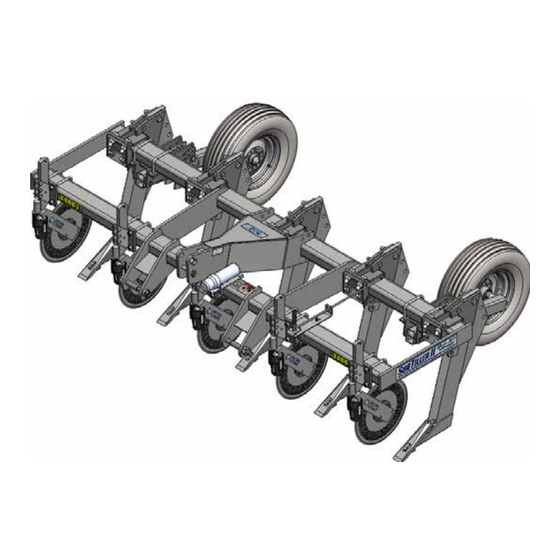
Three Point
T
ll
ub
iller
T
ll • S
iller
ub
4 x 6 x 11' Frame
T
ll
ub
iller
T
ll • S
iller
ub
T
ll
5 Shank 30"
ub
iller
T
ll • S
iller
ub
Assembly
T
ll
ub
iller
T
ll • S
iller
ub
and Operators
T
ll
ub
iller
T
ll • S
iller
ub
Manual
T
ll
ub
iller
T
ll • S
iller
ub
T
ll
ub
iller
T
ll • S
iller
ub
T
ll
ub
iller
T
ll • S
iller
ub
T
ll
ub
iller
T
ll • S
iller
ub
T
ll
ub
iller
T
ll • S
iller
ub
T
ll
ub
iller
T
ll • S
iller
ub
T
ll
ub
iller
T
ll • S
iller
ub
T
ll
ub
iller
T
ll • S
iller
ub
T
ll
ub
iller
Manual Number 70200003
T
ll • S
iller
ub
Rev. 6-13-16
• S
T
ll
ub
iller
T
ll • S
iller
ub
T
ILLER
II
TM
$10.00 Net
Advertisement
Table of Contents

Subscribe to Our Youtube Channel
Related Manuals for BLU-JET SubTiller II


Summary of Contents for BLU-JET SubTiller II
- Page 1 ll • S ll • S iller iller iller ll • S ll • S ll • S ller iller iller ll • S ll • S iller iller iller ll • S ll • S ll • S ller iller iller ll •...
- Page 2 • Box 218 • Thurston, Nebraska, 68062-0218 Phone: 402-385-3041 • Fax: 402-385-3043 E-mail: box218@thurstonmfgco.com • Design specifications and features as described are subject to change without notice. BLU-JET is a registered trademark of Thurston Manufacturing Company, Thurston NE. /SIronWorks @SIronWorks...
-
Page 3: Table Of Contents
Operating Instructions..................Specifications..................... 12 Parts........................ 13 Frame, 4” x 6”, 11’, Base Unit (70210684)............. Frame, SubTiller II, 11’, 4” x 6”, 3 Point (70210071)......... 14 Manual Holder (AAM2639)................15 Pin Adjust Gauge Wheels (70210150)............16 Super 1200 Coulter (70210296)..............17 Coulter Arm With Hub and Knee Casting (AM2799)........ -
Page 4: Subtiller Ii
Introduction Task Procedures Illustrations SubTiller II elcome to Thurston Manufacturing Company. Our goal is to provide quality products and services to our customers. The company’s BLU- JET products have a reputation for quality, excellence in design and proven durability. Energetic, resourceful and continuous improvement goals in Environmental, Safety, Quality, Production and Engineering keep our firm at the cutting edge of technology. - Page 5 Introduction Task Procedures Illustrations SubTiller II General Information: The BLU-JET SubTiller II lifts and fractures hardpan and wheel compaction. Shank penetrate 14” to 18”, fracturing on either side of the shank. The BLU-JET SubTiller II was designed to be used in combination with Super 1200 Coulters to easily cut through residue. arranty is provided for customers who operate and maintain their equip- ment as described in this manual. Warranty registration is accomplished by the dealer completing and forwarding the WARRANTY REGISTRATION FORM to Thurston Manufacturing Company. It is in your best interest to insure that this has been done.
-
Page 6: Dealer Checklist
Dealer Checklist Task Procedures Illustrations SubTiller II o The Dealer: Inspect the implement thoroughly after assembly to be certain it is functioning properly before delivering it to the customer. The following checklist is a reminder of points to cover. Check off each item as it is found satisfactory or after proper adjustment is made. -
Page 7: To The Owner
To The Owner Task Procedures Illustrations SubTiller II hank you for your recent purchase of a new BLU-JET im- plement. The primary objective of Thurston Manufacturing Company is to build and provide you with a quality product. However, in the event that a problem does occur, it is im- perative that your warranty registration is on file in order to accurately respond to your specific service circumstances. -
Page 8: Warranty
Limited Warranty Task Procedures Illustrations SubTiller II hurston Manufacturing Company warrants each new BLU-JET machine primary framework to be free from defects in material and workmanship for a period of five (5) years, normal wear of wearing parts excepted. Thurston Manufacturing Company further warrants each new BLU-JET product to be free from defects in material and workmanship, normal wear of wearing parts excepted, for a period of one (1) year. All accessories purchased and resold by Thurston Manufacturing Company will be warranted according to their respective manufacturer. Tires on BLU-JET equipment are warranted through their respective tire manufacturers and their network of dealers in your local area. -
Page 9: Safety
Safety Task Procedures Illustrations RECOGNIZE SAFETY INFORMATION SubTiller II • This is the safety-alert symbol. When you see his symbol on your machine or in this manual, be alert to the potential for personal injury. Follow recommended precautions and safe operating practices. FOLLOW SAFETY INSTRUCTIONS • Carefully read all safety messages in this manual and on your machine safety signs. Keep safety signs in good condition. Replace missing or damaged safety signs. - Page 10 Safety Task Procedures Illustrations SubTiller II HIGHWAY AND TRANSPORT OPERATIONS • Plan your route to avoid heavy traffic. • Be a safe and courteous driver. Always yield to oncoming traffic in all situations, including narrow bridges, intersection, etc. • Be observant of bridge loading ratings. Do not cross bridges rated lower than the gross weight at which you are operating. • Always operate equipment in a position to provide maximum visibility at all times. Makes allowances for increased length and weight of the equipment when making turns, stopping the unit, etc.
-
Page 11: Operating Instructions
WARNING: Thurston Manufacturing does not recommend the use of three point SUBTILLER ll WARNING on articulated four wheel drive tractors. Damage to the tractor or SUBTILLER II will not be covered under warranty. SUBTILLER II used with articulated four wheel drive tractors should be pull type models. - Page 12 8”-14” depth. Do not run the SubTiller II point too deep. This may result in wasted horsepower and a slicing effect through the hardpan rather than a lifting and shattering effect directly under the compacted zone.
- Page 13 Operating Instructions Task Procedures Illustrations SubTiller II Changing Points The fall and summer points should rest flatly on metal shims placed between the lower shank and the point. Do not tighten with impact wrench. Over tightening can cause damage to point. Coulters Coulter should be adjusted to slice 3” to 4” deep during operation. Running coulters too deep may result in premature bearing failure. Grease coulter pivot shaft gener-...
-
Page 14: Specifications
Specifications Task Procedures Illustrations Frame............... 11’, 4” x 6” x 1/2” SubTiller II Tractor Attachment......... 3 Point Pull Pin Kit............CATEGORY II & III Gauge Wheel .......... Pin Adjust Gauge Wheel Tire........... 9.5L-15-6ply (Tire Pressure 32 PSI Max.) Working Depths: Fall Point............ 14-18” Summer Point..........10-18”... -
Page 15: Parts
70210684, Frame, 4 x 6, 11’ Base Unit 5 Shank 30” Task Procedures Illustrations SubTiller II 70210684, FRAME, 4”X 6”, 11’, 5 SHANK 30” BASE UNIT BOM ID Item No Description 70210071 FRAME, SUBTILLER II, 11’, 4” X 6”, 3-POINT 70210150 GAUGE WHEEL, PIN ADJUST, 9.5L-15 WHEEL (SET OF 2) 70210296 COULTER, SUPER 1200, SUBTILLER II 3-POINT, 5 ROW 70210397 SHANK, MOUNTING, REINFORCED SHEARBOLT, SUBTILLER, 5 ROW 80210202 KIT, SUBTILLER II PULL PIN, CATEGORY II AAM2717 SOIL PROBE & MOUNTING, 6” X 4” HARDWARE AP2701 COULTER BLADE 20” FLUTED... - Page 16 70210071, Frame, SUBTILLER II, 11’, 4” x 6”, 3 Point Task Procedures Illustrations SubTiller II 70210071, FRAME, SUBTILLER II, 11’, 4” X 6” 3-POINT BOM ID Item No Description AAM2639 MANUAL HOLDER WITH 6”X 4” MOUNTING AM7640 BRACKET, MOUNTING, MANUAL HOLDER AP4254 MANUAL HOLDER, BLACK BP3001 NUT, HEX, 3/8”-16, GRADE 2, PLATED BP3002 WASHER, LOCK, 3/8”, PLATED BP3006 HEX CAP SCREW, 3/8”-16 X 1”, GRADE 5, PLATED BP3045 U-BOLT, 3/8”-16 X 6”W X 5”L, PLATED AM24002 FRAME, SUBTILLER II, 11’, 3-POINT AP2215 DECAL, BLU-JET, 3” X 8” AP2217 DECAL, SUBTILLER II, 4” X 20” AP2231 DECAL, FEMA, 2-1/2” X 1-1/2” AP2483 DECAL, DANGER, FALLING FROM EQUIPMENT AP2547 DECAL, REFLECTOR, YELLOW, 2” X 9” AP2548 DECAL, REFLECTOR, RED, 2” X 9”...
-
Page 17: Manual Holder (Aam2639)
AAM2639 Manual Holder With 6” x 4” Mounting Task Procedures Illustrations SubTiller II AAM2639 MANUAL HOLDER WITH 6” X 4” MOUNTING BOM ID Item No Description AM7640 BRACKET, MOUNTING, MANUAL HOLDER BP3045 U-BOLT, 3/8”-16 X 6”W X 5”L AP4254 MANUAL HOLDER, BLACK BP3006 HEX CAP SCREW, 3/8”-16 X 1”, GRADE 5, PLATED BP3002 WASHER, LOCK, 3/8”, PLATED BP3001 NUT, HEX, 3/8”-16, GRADE 2, PLATED Mount (3) (AP4254) manual holder (1) (AM7640 manual holder bracket with (4) (BP3006) 3/8” x 1” hex cap screw. Secure with (5) (BP3002) 3/8” lock washer and (6) (BP3001) 3/8” hex nut. 2. Consult row spacing page for manual holder location. -
Page 18: Pin Adjust Gauge Wheels (70210150)
70210150 (Gauge Wheel Pin Adjust 9.5L-15 Wheel (Set of 2) Task Procedures Illustrations SubTiller II 70210150 GAUGE WHEEL PIN ADJUST 9.5L-15 WHEEL BOM ID Item No Description AAM2766 WHEEL, 9.5L-16, 6 PLY, 15 X 6 X 6, WHITE AP2001 RIM, 15 X 6 X 6, WHITE AP2012 TIRE, 9.5L-15, 6 PLY AP2790 VALVE STEM, METAL AM24024 ASSEMBLY, GAUGE WHEEL LEG, PIN ADJUST AM24025 BRACKET, PIN ADJUST GAUGE WHEEL MOUNTING AP2407 SNAP RING, 1” EXTERNAL, HEAVY DUTY BM3650 PIN, 1” X 5-9/16” BP3034 NUT, HEX, 3/4”-10, GRADE 2, PLATED BP3035 WASHER, LOCK, 3/4”, PLATED BP3051 PIN, 1” X 6”, HITCH, PLATED BP3208 U-BOLT, 3/4”-10 X 6”W X 5-3/4”L, PLATED BP3215 MACHINERY BUSHING, 1-1/2” OD X 1” ID, 14 GAUGE, PLATED BP3511 PIN, COTTER, 3/16” X 1-3/4” AM24024 ASSEMLBY, GAUGE WHEEL LEG, PIN ADJUST BOM ID... -
Page 19: Super 1200 Coulter (70210296)
70210296 (Coulter, Super 1200, SubTiller II, 5 Row) Task Procedures Illustrations SubTiller II 70210296, COULTER, SUPER 1200, SUBTILLER II, 5 ROW 70210296, COULTER, SUPER 1200, SUBTILLER II 3-POINT, 5 ROW BOM ID Item No Description 70210296 COULTER, SUPER 1200, SUBTILLER II 3-POINT, 5 ROW AAM2728 COULTER, SUPER 1200, 16”, 1 ROW AM24011 BRACKET, SUBTILLER II CENTER COULTER AM24034 BRACKET, FLATBACK BP3034 NUT, HEX, 3/4”-10, GRADE 2, PLATED BP3035 WASHER, LOCK, 3/4”, PLATED BP3042 NUT, HEX, 1/2”-13, GRADE 2, PLATED BP3043 WASHER, LOCK, 1/2”, PLATED BP3047 U-BOLT, 3/4”-10 X 4”W X 7-3/4”L BP3229 BOLT, CARRIAGE, 1/2”-13 X 2-1/2”, GRADE 5, PLATED... -
Page 20: Coulter Arm With Hub And Knee Casting (Am2799)
70210296 (5 Row) Super 1200 Flex Coulter and Shank Parts Task Procedures Illustrations SubTiller II AP2707, HUB ASSEMBLY, 4 BOLT BOM ID Qty Item No Description AP2707 HUB ASSEMBLY, 4 BOLT AP2703 HUB CAP, 1610 AP2706-1 HUB W/ CUPS, 4 BOLT, 5” BC, 3.62” PILOT, W/ZERK HOLE AP2075 BEARING CUP, LM 11910 AP2524 BEARING CUP, LM 67010 AP2747 GREASE SEAL, 15235TB AP2023 BEARING CONE, LM 67048 AP2024 BEARING CONE, LM 11949 AP2702 HEX CAP SCREW, 1/2”-20 X 1”, GRADE 5, PLATED BP3072 GREASE ZERK, 1/4”-28 AM2799, ASSEMBLY, COULTER ARM WITH HUB & KNEE CASTING, HD BOM ID Item No Description AM2799 ASSEMBLY, COULTER ARM WITH HUB & KNEE CASTING, HD AM2743 CASTING, COULTER KNEE, HD, MACHINED WITH BUSHINGS AP2274 BUSHING, 1-17/32” OD X 1-3/8” ID” X 1” OAL... -
Page 21: Shank Mounting Reinforced Shearbolt, 1 Row (70210385)
70210397, Shank Mounting Reinforced Shearbolt 5 Row 70210385 Shank Mounting, Reinforced, 1 Row Task Procedures Illustrations SubTiller II 70210385, SHANK MOUNTING, REINFORCED SHEARBOLT, SUBTILLER II BOM ID Item No Description AM7550 SHANK MOUNT, 6” X 4”, SUBTILLER II AM7551 BRACKET, MOUNTING CLAMP, 4”X 6” AM7553 SHANK, SUBTILLER, REINFORCED BP3528 TENSION BUSHING, 1” X 3/4” X 1-1/4” OAL BP3019 NUT, HEX, 1”-8, GRADE 2, PLATED BP3020 WASHER, LOCK, 1”, PLATED BP3021 HEX CAP SCREW, 3/4”-10 X 4-1/2”, GRADE 2, PLATED BP3034 NUT, HEX, 3/4”-10, GRADE 2, PLATED BP3035 WASHER, LOCK, 3/4”, PLATED BP3042 NUT, HEX, 1/2”-13, GRADE 2, PLATED BP3043 WASHER, LOCK, 1/2”, PLATED BP3050 WASHER, FLAT, 1/2”, PLATED BP3129 HEX CAP SCREW, 1/2”-13 X 3”, GRADE 5, PLATED BP3256 HEX CAP SCREW, 1”-8 X 5”, GRADE 5, PLATED BP3263 HEX CAP SCREW, 1”-8 X 3-1/2”, GRADE 8, PLATED... -
Page 22: Pull Pin Kit Category Ii/Iii (88210202)
80210202, Pull Pin Kit Category II Task Procedures Illustrations SubTiller II 80210202, KIT, PULL PIN CATEGORY II 80210202, KIT, SUBTILLER II PULL PIN, CATEGORY II BOM ID Item No Description 80210202 KIT, SUBTILLER II PULL PIN, CATEGORY II BM3630 PIN, CATEGORY II, LOWER LINK BM3808 BUSHING BP3129 HEX CAP SCREW, 1/2”-13 X 3”, GRADE 5, PLATED BP3244 NUT, HEX LOCK, 1/2”-13, PLATED BP3508 PIN, CATEGORY II TOP LINK, 1” X 4-5/8” BP3517 LYNCH PIN, 7/16”... -
Page 23: Soil Probe (Aam2717)
AAM2717, Soil Probe & Mounting 6” x 4” Hardware Task Procedures Illustrations SubTiller II AAM2717, SOIL PROBE & MOUNTING, 6” X 4” HARDWARE AAM2717, SOIL PROBE & MOUNTING, 6” X 4” HARDWARE BOM ID Item No Description AAM2717 SOIL PROBE & MOUNTING, 6” X 4” HARDWARE AM7646 BRACKET, SOIL PROBE STORAGE AM7647 SOIL PROBE BP3001 NUT, HEX, 3/8”-16, GRADE 2, PLATED BP3002 WASHER, LOCK, 3/8”, PLATED BP3045 U-BOLT, 3/8”-16 X 6”W X 5”L, PLATED... -
Page 24: Assembly
Assembly (Shank Mounting) Task Procedures Illustrations SubTiller II Positioning Position SubTiller mainframe on sturdy stands, about 35” mainframe high on hard level surface. on stands Clamp frame to stands to NOTE: stabilize. Hydraulic Optional gauge wheels Pull Type Consult row spacing pages must be and mark out rows on back mounted bars. -
Page 25: Cutting Edge Mounting
Assembly (Shank and Cutting Edge) Task Procedures Illustrations SubTiller II Mounting Push bottom of the shank in until (a) (BP3021) 3/4”-10 shank BP3034 BP3035 x 4-1/2”, grade 2, hex cap continued screw can be inserted. Secure with (b) (BP3035) 3/4” lock BP3021 washer and (c) (BP3034) 3/4” hex nut. BP3034 Insert spare (a) (BP3021) 3/4”- 10 x 4-1/2”, grade 2, hex cap screw in storage hole at the top of mounting bracket. -
Page 26: Points, Fall And Summer, Mounting
Assembly (Points) Task Procedures Illustrations SubTiller II Attaching Insert the head of (a) (BP3440) 1/2”-13 x 9”, grade 2, carriage points bolt into notch in point. Start carriage bolt through hole in shank. Hook the point over BP3042 the end of the shank and position Vee over cutting edge end. Place (b) (BP3050) 1/2” flat washer, and (c) (BP3043) 1/2”... -
Page 27: Coulter Assembly
Assembly (Coulter) Task Procedures Illustrations SubTiller II 1. Remove hex cap screws from Preparing coulter hub. coulters mounting 2. Place (AP2701) 20” fluted Attaching coulter blade on coulter 20” fluted assembly and replace hex blades to cap screws. coulter assembly 3. Install (BP3205) 2-1/2” x 1-3/4” Placing machinery bushing over machinery (AM2735) 16” coulter shank bushing weldment. -
Page 28: Coulter Mounting
Assembly (Coulters) Task Procedures Illustrations SubTiller II Mounting Mark out rows on toolbar and coulters center (a) (AM24034) flatbacks on marks. Insert (b) (BP3047) 3/4”-10 x 4”W x 7-3/4”L, u-bolts. BP3047 Secure u-bolts with (d) (BP3035) 3/4” lock washers and (c) (BP3034) 3/4” hex nuts. AM24034 BP3034 BP3035 Place (e) (AAM2728) Super BP3043 1200 coulter assembly into AAM2728 bracket. Insert (f) (BP3229) 1/2”-13 x 2-1/2”, grade 5 carriage bolts. BP3229 Install (g) (BP3043) 1/2” lock washers and (h) (BP3042) 1/2”... -
Page 29: Pin Adjust Gauge Wheel Mounting
70210150 Assembly (Pin Adjust Gauge Wheel) Task Procedures Illustrations SubTiller II Mounting Consult row spacing pages and mark out placement on pin adjust the back bar. gauge BP3205 wheels Position (a) (AM24025) adjust gauge wheel bracket NOTE: on mainframe and secure Consult AM24025 with two (b) (BP3205) 3/4-10 row spacing x 6”W x 5-3/4”L, u-bolts,... -
Page 30: Manual Holder Mounting
AAM2639 Manual Holder With 6” x 4” Mounting Task Procedures Illustrations SubTiller II Installation manual holder AAM2639 MANUAL HOLDER WITH 6” X 4” MOUNTING BOM ID Item No Description AM7640 BRACKET, MOUNTING, MANUAL HOLDER BP3045 U-BOLT, 3/8”-16 X 6”W X 5”L AP4254 MANUAL HOLDER, BLACK BP3006 HEX CAP SCREW, 3/8”-16 X 1”, GRADE 5, PLATED BP3002 WASHER, LOCK, 3/8”, PLATED BP3001 NUT, HEX, 3/8”-16, GRADE 2, PLATED Mount (3) (AP4254) manual holder (1) (AM7640 manual holder bracket with (4) (BP3006) 3/8” x 1” hex cap screw. Secure with (5) (BP3002) 3/8” lock washer and (6) (BP3001) 3/8” hex nut. 2. Consult row spacing page for manual holder location. -
Page 31: Pull Pin Kit Installation
80210202, Pull Pin Kit Category II Task Procedures Illustrations SubTiller II Installation pull pins 80210202, KIT, PULL PIN CATEGORY II 80210202, KIT, SUBTILLER II PULL PIN, CATEGORY II BOM ID Item No Description 80210202 KIT, SUBTILLER II PULL PIN, CATEGORY II BM3630 PIN, CATEGORY II, LOWER LINK BM3808 BUSHING BP3129 HEX CAP SCREW, 1/2”-13 X 3”, GRADE 5, PLATED BP3244 NUT, HEX LOCK, 1/2”-13, PLATED BP3508 PIN, CAT II TOP LINK, 1” X 4-5/8” BP3517 LYNCH PIN, 7/16” 1. Install pull pins. -
Page 32: Soil Probe Mounting
AAM2717, Soil Probe Task Procedures Illustrations SubTiller II Installation of soil probe AAM2717, SOIL PROBE & MOUNTING, 6” X 4” HARDWARE AAM2717, SOIL PROBE & MOUNTING, 6 X 4 HARDWARE BOM ID Item No Description AAM2717 SOIL PROBE & MOUNTING, 6” X 4” HARDWARE AM7646 BRACKET, SOIL PROBE STORAGE AM7647 SOIL PROBE BP3001 NUT, HEX, 3/8”-16, GRADE 2, PLATED BP3002 WASHER, LOCK, 3/8”, PLATED BP3045 U-BOLT, 3/8”-16 X 6”W X 5”L, PLATED 1. Install soil probe. -
Page 33: Decal Installation
70210071, Frame, SubTiller II, 11’, 4” x 6”, 3 Point Task Procedures Illustrations SubTiller II Decal installation 70210071, FRAME, SUBTILLER II, 11’, 4” X 6” 3-POINT BOM ID Item No Description AAM2639 MANUAL HOLDER WITH 6”X 4” MOUNTING AM7640 BRACKET, MOUNTING, MANUAL HOLDER AP4254 MANUAL HOLDER, BLACK BP3001 NUT, HEX, 3/8”-16, GRADE 2, PLATED BP3002 WASHER, LOCK, 3/8”, PLATED BP3006 HEX CAP SCREW, 3/8”-16 X 1”, GRADE 5, PLATED BP3045 U-BOLT, 3/8”-16 X 6”W X 5”L, PLATED AM24002 FRAME, SUBTILLER II, 11’, 3-POINT AP2215 DECAL, BLU-JET, 3” X 8” AP2217 DECAL, SUBTILLER II, 4” X 20” AP2231 DECAL, FEMA, 2-1/2” X 1-1/2” AP2483 DECAL, DANGER, FALLING FROM EQUIPMENT AP2547 DECAL, REFLECTOR, YELLOW, 2” X 9” AP2548 DECAL, REFLECTOR, RED, 2” X 9”... -
Page 34: Pull Type Kit
70210724, Hitch Kit, Singles, Clevis & Category III Task Procedures Illustrations SubTiller II DP5011, HOSE, HYDRAULIC, 70210244, HYDRAULIC GAUGE 3/8” X 180” (15’0”) WHEELS, HEAVY DUTY SINGLES, 10FJX-10FJX 8’ & 11’ FRAMES DP5094, HOSE, HYDRAULIC, 3/8” X 276” (23’0”) 8MP-10FJX DP5094, HOSE, HYDRAULIC, 3/8” X 276” (23’0”) 8MP-10FJX 70210695, HITCH KIT, CLEVIS, CATEGORY III 70210724, HITCH KIT, SUBTILLER II, SINGLES CLEVIS, CATEGORY III 70210724, HITCH KIT, SINGLES, CLEVIS & CATEGORY III BOM ID Item No Description 70210724 HITCH KIT, SUBTILLER II, SINGLES, CLEVIS & CATEGORY III 70210244 HYDRAULIC GAUGE WHEELS, HEAVY DUTY SINGLES, 8’ & 11’ FRAMES 70210695 HITCH KIT, SUBTILLER II, CLEVIS & CATEGORY III DP5011 HOSE, HYDRAULIC, 3/8” X 180” (15’ 0”), 10FJX-10FJX DP5094 HOSE, HYDRAULIC, 3/8” X 276” (23’ 0”), 8MP-10FJX... -
Page 35: Hitch Kit, Subtiller Ii, Clevis & Category
70210695, Hitch Kit, Clevis & Category III Task Procedures Illustrations SubTiller II 70210695, HITCH KIT, CLEVIS & CATEGORTY III BOM ID Item No Description 70210364 TONGUE, SUBTILLER II CONVERSION, CATEGORY III AAM4768 ASSEMBLY, TURNBUCKLE AM2197 BRACKET, WRENCH STORAGE AM2518 JACK, 9TWDL (TOP WIND DROP LEG) AM2526 CRANK WITH GRIP AP2413 GRIP, JACK HANDLE AM4759 TURNBUCKLE WRENCH, 3-1/16” AP2413 GRIP, WRENCH HANDLE AM7224 TONGUE, CATEGORY III AP2150 TRANSPORT CHAIN, 20,000#, 3/8” AP2215 DECAL, BLU-JET, 3” X 8” AP2222 DECAL, STAND CLEAR OF TONGUE, TONGUE LIGHT AP2231 DECAL, FEMA, 2-1/2” X 1-1/2” AP2282-1 HOSE RETAINER, 4” X 6”, WITH PLASTIC CAPS AP2469 DECAL, SAFETY CHAIN... -
Page 36: Hydraulic Gauge Wheels Heavy Duty Singles, 8' &11' (70210244)
70210244, Hydraulic Gauge Wheels, Heavy Duty Singles, 8’ &11’ Frames Task Procedures Illustrations SubTiller II 70210090, HYDRAULIC GAUGE WHEELS UPRIGHT BRACES 70210244, HYDRAULIC GAUGE WHEELS, HEAVY DUTY SINGLES, 8’ & 11’ FRAMES... - Page 37 70210244, Hydraulic Gauge Wheels, Heavy Duty Singles, 8’ &11’ Frames Task Procedures Illustrations SubTiller II 70210244, HYD GAUGE WHEELS, HEAVY DUTY SINGLES, 8’ & 11’ FRAMES BOM ID Item No Description 70210244 HYDRAULIC GAUGE WHEELS, HEAVY DUTY SINGLES, 8’ & 11’ FRAMES 70210090 HYDRAULIC GAUGE WHEEL UPRIGHT BRACE AM2760 BRACE, SUBTILLER II, CYLINDER UPRIGHT BM3560 PIN, 1” X 4-1/8” BP3034 NUT, HEX, 3/4”-10, GRADE 2, PLATED BP3047 U-BOLT, 3/4”-10 X 4”W X 7-3/4”L BP3511 PIN, COTTER, 3/16” X 1-3/4” AAM2098 SMV KIT, 4” X 6” (SLOW MOVING VEHICLE) AM4077 BRACKET, SMV MOUNTING AP2542 SMV SIGN AP2543 SMV MOUNTING SOCKET AP2544 SMV MOUNTING SPADE BP3001 NUT, HEX, 3/8”-16, GRADE 2, PLATED BP3002 WASHER, LOCK, 3/8”, PLATED BP3045 U-BOLT, 3/8”-16 X 6”W X 5”L, PLATED...
-
Page 38: Pull Type, Dual Wheel Hydraulic Gauge Wheel Kit (70210725)
70210725, Hitch Kit, SubTiller II, Duals Task Procedures Illustrations SubTiller II DP5094, HOSE, HYDRAULIC, DP5011, HOSE, HYDRAULIC, 70210182, HYDRAULIC GAUGE 3/8” X 276” (23’0”) 3/8” X 180” (15’0”) WHEELS, HEAVY DUTY DUALS, 8MP-10FJX 10FJX-10FJX 16’ & 21’ FRAMES DP5094, HOSE, HYDRAULIC, 70210695, HITCH KIT, 70210724, HITCH KIT, SUBTILLER II, DUALS 3/8” X 276” (23’0”) CLEVIS, CATEGORY III 8MP-10FJX 70210725, HITCH KIT, SUBTILLER II, DUALS BOM ID Item No Description 70210725 HITCH KIT, SUBTILLER II, DUALS 70210182 HYDRAULIC GAUGE WHEELS, HEAVY DUTY DUALS, 16’ & 21’ FRAMES 70210695 HITCH KIT, SUBTILLER II, CLEVIS & CATEGORY III DP5011 HOSE, HYDRAULIC, 3/8” X 180” (15’ 0”), 10FJX-10FJX DP5094 HOSE, HYDRAULIC, 3/8” X 276” (23’ 0”), 8MP-10FJX... -
Page 39: Hitch Kit, Subtiller Ii, Clevis & Category Iii (70210695)
70210695, Hitch Kit, SubTiller II, Clevis & Category III Task Procedures Illustrations SubTiller II 70210695, HITCH KIT, SUBTILLER II, CATEGORY III BOM ID Item No Description 70210364 TONGUE, SUBTILLER II CONVERSION, CATEGORY III AAM4768 ASSEMBLY, TURNBUCKLE AM2197 BRACKET, WRENCH STORAGE AM2518 JACK, 9TWDL (TOP WIND DROP LEG) AM2526 CRANK WITH GRIP AP2413 GRIP, JACK HANDLE AM4759 TURNBUCKLE WRENCH, 3-1/16” AP2413 GRIP, WRENCH HANDLE AM7224 TONGUE, CATEGORY III AP2150 TRANSPORT CHAIN, 20,000#, 3/8” AP2215 DECAL, BLU-JET, 3” X 8” AP2222 DECAL, STAND CLEAR OF TONGUE, TONGUE LIGHT AP2231 DECAL, FEMA, 2-1/2” X 1-1/2” AP2282-1 HOSE RETAINER, 4” X 6”, WITH PLASTIC CAPS AP2469 DECAL, SAFETY CHAIN... -
Page 40: Hydraulic Gauge Wheels Heavy Duty Duals, 8' &11' (70210182)
70210182, Hydraulic Gauge Wheels, Heavy Duty Duals, 16’ & 21’ Frames Task Procedures Illustrations SubTiller II 70210090, HYDRAULIC GAUGE WHEELS UPRIGHT BRACES 70210182, HYDRAULIC GAUGE WHEELS, HEAVY DUTY DUALS, 16’ & 21’ FRAMES... - Page 41 70210182, Hydraulic Gauge Wheels, Heavy Duty Duals, 16’ & 21’ Frames Task Procedures Illustrations SubTiller II BOM ID Item No Description 70210182 HYDRAULIC GAUGE WHEELS, HEAVY DUTY DUALS, 16’ & 21’ FRAMES 70210090 HYDRAULIC GAUGE WHEEL UPRIGHT BRACE AM2760 BRACE SUBTILLER II CYLINDER UPRIGHT BM3560 PIN, 1” X 4-1/8” BP3034 NUT, HEX, 3/4”-10, GRADE 2, PLATED BP3047 U-BOLT, 3/4”-10 X 4”W X 7-3/4”L BP3511 PIN, COTTER, 3/16” X 1-3/4” AAM2098 SMV KIT, 4” X 6” (SLOW MOVING VEHICLE) AM4077 BRACKET, SMV MOUNTING AP2542 SMV SIGN AP2543 SMV MOUNTING SOCKET AP2544 SMV MOUNTING SPADE BP3001 NUT, HEX, 3/8”-16, GRADE 2, PLATED BP3002 WASHER, LOCK, 3/8”, PLATED BP3045 U-BOLT, 3/8”-16 X 6”W X 5”L, PLATED AAM2709 ASSEMBLY, HUB AND SPINDLE, 611 HUB, 1-3/4” X 11”...
-
Page 42: 9Tw25Dl Top Wind Drop Leg Jack (Am2518)
AM2518, 9TW25DL (Top Wind Drop Leg) Jack Task Procedures Illustrations SubTiller II AM2518 JACK, 9TWDL TOP WIND DROP LEG BOM ID Qty Item No Description AM2524 INTERMEDIATE TUBE WITH PLUNGER ASSEMBLY AM2525 DROP LEG WITH PAD & HANDLE AM2534 SCREW ASSEMBLY, 4” AM2539 TOP TUBE, WITH BOLT ON MOUNTING AP2407 SNAP RING, 1” EXTERNAL, HEAVY DUTY AP2410 THRUST BEARING, NICE 609 EM1736 BEARING SEAT EM1739 EM3016 9000# LABEL... -
Page 43: Hub And Spindle Assembly, 611 Hub, 1-3/4" X 11"(Aam2709)
AAM2709 ASSEMBLY, HUB AND SPINDLE, 611 HUB, 1-3/4” X 11” Task Procedures Illustrations SubTiller II AAM2709 ASSEMBLY, HUB AND SPINDLE, 611 HUB, 1-3/4” X 11” BOM ID Item No Description AP2023 BEARING CONE, LM 67048 AP2048 HUB CAP, 1513 AP2049 WHEEL BOLT, 1/2”-20 X 1” AP2066 GREASE SEAL, CR 16289 AP2078 BEARING CONE, JL 69349 AP2123 HUB WITH CUPS, 6 BOLT, 611301-6 AP2077 BEARING CUP, JL 69310 AP2123-Hub HUB, 6 BOLT, 611301-6 AP2524 BEARING CUP, LM 67010 BP3072 GREASE ZERK, 1/4”-28 AP2146 WASHER, SPINDLE, 2” X 1-1/16” X .134” AP2167 SPINDLE, 1-3/4” X 11”, S7203-F-00 AP2426 PIN, COTTER, 5/32” X 1-3/4” AP2811 NUT, SPINDLE, 1”-14... -
Page 44: Assembly
Assembly (Hydraulic Gauge Wheels) Task Procedures Illustrations SubTiller II Mounting cylinder uprights BP3516 BP3290 AM3346 AM5049 BP3275 NOTE: Consult row spacing drawings Consult (a) (AM3346) cylinder row spacing upright placement. pages for cylinder Center upright and install upright (b) (AM5049) cylinder upright locations clamp bracket with six (c) (BP3290) 1’’ x 3”, grade 8, hex... -
Page 45: Upright Braces
Assembly (Hydraulic Gauge Wheels) Task Procedures Illustrations SubTiller II Mounting upright AM2760 BP3047 brace BM3560 BP3511 BP3034 Adjust brace and insert Position (a) (AM2760) SUB- (d) (BM3560) 1” x 4-1/8” pin. TILLER II Secure with two (e) (BP3511) upright brace behind cylinder 3/16” x 1-3/4” cotter pins after upright. cylinders are installed. Insert (b) (BP3047) 3/4” x 4”W Tighten 3/4” hex nuts on x 7-3/4”L, u-bolts over frame u-bolts. into brace. Start (c) (BP3034) 3/4” hex nuts on each u-bolt. -
Page 46: Pivot Brackets
Assembly (Hydraulic Gauge Wheels) Task Procedures Illustrations SubTiller II Inserting pivot brackets NOTE: Left-hand right-hand as viewed from the rear. AM5038 AM3039 Insert (a) (AM5038) pivot arm bracket “A” into right-hand side from the rear, of the upright. Insert (b) (AM5039) pivot arm bracket “B” into left-hand side from the rear, of the... -
Page 47: Wheel Legs
Assembly (Hydraulic Gauge Wheels) Task Procedures Illustrations SubTiller II Mounting wheel leg BP3140 BP3035 BP3516 BP3034 AM5018 Position (a) (AM5018) wheel leg Secure with (c) (BP3035) 3/4” bolt-on spindle loop between lock washers and (d) (BP3034) pivot brackets. 3/4” hex nuts. Install (e) (BP3516) 1-1/4” x 1” Insert (b) (BP3140) 3/4” x 2-1/2” hex cap screws. x 1” tension bushing in wheel leg weldment. -
Page 48: Single Wheel Cylinders
Assembly (Hydraulic Single Gauge Wheels) Task Procedures Illustrations SubTiller II Mounting cylinders NOTE: Left-hand right-hand as viewed from the rear. DP4486 AM3039 BM3520 DP4143 Left-hand from the rear DP4485 Left-hand from the rear Right-hand from the rear Install (c) (AM3039) transport cylinder Remove upright cylinder pins locks and secure with (d) (BM3520) and install (a) (DP4486) 4 x 12” transport lock clip pins. -
Page 49: Single Wheel Bolt-On Adapter And Hub And Spindle
Assembly (Hydraulic Single Gauge Wheels) Task Procedures Illustrations SubTiller II Mounting single wheel bolt-on adapter and hub and spindle BP3140 AM5019 BP3035 BP3034 AAM2709 Mount (a) (AM5019) single wheel bolt-on adapter to wheel leg with (b) (BP3140) 3/4” x 2-1/2” hex cap screws (c) (BP3035) 3/4” lock washers and (d) (BP3034) 3/4” hex nuts. Turn set screws out and insert (e) (AAM2709) 1-3/4” x 11”, 611 hub and spindle. Allow 3/4” inch between the hub and bracket weldment. -
Page 50: Single Wheel Mounting
Assembly (Hydraulic Single Gauge Wheels) Task Procedures Illustrations SubTiller II Mounting wheels AAM2766 Remove wheel bolts and mount (a) (AAM2766) 9.5L-16, 6 ply, 15 x 6 x 6, wheel. Valve stem to the outside. -
Page 51: Dual Gauge Wheel Cylinders
Assembly (Hydraulic Dual Gauge Wheels) Task Procedures Illustrations SubTiller II Mounting cylinders NOTE: Left-hand right-hand as viewed from the rear. DP4487 BM3520 Remove upright cylinder pins and install (a) (DP4487) 4-1/2” x 12” rephasing cylinder on the left-hand side from the rear. Install (b) (AM4721) transport cylinder lock, 1-3/4” x 2” AM4721 cylinder rod and secure with (c) (BM3520) transport lock clip pins. Install (d) (DP4143) 10MJIC- DP4143 8MSAE, 90 degree adapters. -
Page 52: Dual Gauge Wheel Bolt-On Adapter And Hub And Spindle
Assembly (Hydraulic Dual Gauge Wheels) Task Procedures Illustrations SubTiller II Mounting dual wheel bolt-on adapter and hub and spindle BP3140 AM5020 AAM2709 BP3035 BP3034 Mount (a) (AM5020) dual wheel bolt-on adapter 1-3/4” loop to wheel leg with (b) (BP3140) 3/4” x 2-1/2” hex cap screws (c) (BP3035) 3/4” lock washers and (d) (BP3034) 3/4” hex nuts. Turn set screws out and insert (e) (AAM2709) 1-3/4” x 11”, 611 hub and spindle. Allow 7/8” inch between the hub and bracket weldment. -
Page 53: Dual Wheel Mounting
Assembly (Hydraulic Dual Gauge Wheels) Task Procedures Illustrations SubTiller II Mounting wheels AAM2766 AAM2766 Remove wheel bolts and mount (a) (AAM2766) 9.5L-16, 6 ply, 15 x 6 x 6, wheels. Valve stem to the outside. -
Page 54: Depth Collars And Smv (Slow Moving Vehicle)
Assembly (Hydraulic Gauge Wheels) Task Procedures Illustrations SubTiller II AP2542 AP2544 BP3002 BP3076 BP3001 AM4077 BP3002 AAM2098 SMV Kit BP3001 AP2543 AM2090 BP3045 BP3045 Position (a) (AM2090) depth Attach (h) (AP2543) SMV mounting Mounting collar brackets near uprights. socket to bracket with hardware depth collar Secure with (b) (BP3045) provided. -
Page 55: Tongue Assembly
Assembly (Hydraulic Gauge Wheels) Task Procedures Illustrations SubTiller II Mounting tongue assembly 1. Complete assembly of SubTiller before installing tongue assembly. Remove pull pins and install (a) (AM7224) CAT III tongue. AM7224... -
Page 56: Turnbuckle
Assembly (Hydraulic Gauge Wheels) Task Procedures Illustrations SubTiller II Mounting turnbuckle assembly EM3735 AAM4768 BP3519 Pull pin BM3610 1. Insert (a) (EM3735) bushing before attaching (b) (AAM4768) turnbuckle assembly to 3rd link. Secure with pull pin. Raise tongue and attach turnbuckle to hitch end with (c) (BM3610) 1-3/4” x 6-1/8” pin. Secure with (d) (BP3519) 3/8” x 2-1/2” roll pin. -
Page 57: Jack
Assembly (Hydraulic Gauge Wheels) Task Procedures Illustrations SubTiller II Mounting Position (a) (AM2518) 21-3/4” jack 9TW-25DL top wing DL jack on tongue, 21-3/4” from hitch plate on tongue weldment. Insert (b) (BP3099) 5/8” x 6”W x 6”L u-bolts. Secure with (c) (BP3038) 5/8” hex nuts. BP3015 BP3096 AM2526 BP3003 BP3038 AM2518 BP3099 Attach (d) (AM2526) jack handle with (e) (BP3096) 3/8” x 2-1/2” hex cap screw, two (g) (BP3015) 3/8” flat washers and (h) -
Page 58: Hitch And Transport Chain
Assembly (Hydraulic Gauge Wheels) Task Procedures Illustrations SubTiller II Mounting hitch and transport BP3519 BP3051 chain AP2850 AP2150 BM3610 BP3511 Attach (d) (AP2850) CAT III Install (a) (AP2150) 20,000# perfect hitch with (e) (BP3051) transport chain in bottom 1” x 6” hitch pins. hitch hole with (b) (BM3610) Secure with (f) (BP3511) 3/16” 1-3/4” x 6-1/8” pin. x 1-3/4” cotter pins. -
Page 59: Hose Tenders
Assembly (Hydraulic Gauge Wheels) Task Procedures Illustrations SubTiller II Installing hose retainers AP2282-1 Mount (a) (AP2282-1) 4 x 6 hose retainers on both sides of the tongue. -
Page 60: Turnbuckle Wrench And Hitch Storage Brackets
Assembly (Hydraulic Gauge Wheels) Task Procedures Illustrations SubTiller II Mounting wrench and hitch storage brackets BP3500 AM4759 AM2144 BP3001 BP3002 BP3002 BP3001 AM2197 AAM2424 BP3045 Attach (f) (AAM2424) hitch Mount (a) (AM2197) wrench storage bracket with storage bracket with (BP3045) 3/8” x 6”w x 5”L (BP3045) 3/8” x 6”w x 5”L u-bolt, (c) (BP3002) 3/8” lock u-bolt, (c) (BP3002) 3/8” lock washers and (d) (BP3001) -
Page 61: Hydraulic Hoses For Single And Dual Gauge Wheels
Assembly (Hydraulic Hoses, Single and Dual Gauge Wheels) Task Procedures Illustrations SubTiller II Attaching hydraulic DP5011 hoses for singles DP5094 and duals NOTE: Left-hand Right-hand DP4007 right-hand as viewed from the rear. Left-hand DP5094 Install (c) (DP4007) 1/2” male Attach (a) (DP5094) 3/8” x 276” tip quick coupler 8FP on hose. (23’ 0”), hose to rod end of right-hand cylinder. Attach (b) (DP5011) 3/8” x 180” Extend hose down right-hand (15’ 0”), hose to butt end of side of tongue to hitch. -
Page 62: Pull Type Decals
Assembly (Hydraulic Single and Dual Gauge Wheels Decals) Task Procedures Illustrations SubTiller II Decals AP2222 AP2215 AP2215 AP2914 AP2469 AP2231 a. AP2215 2 Decal, BLU-JET, 3” x 8” b. AP2914 1 Decal, Warning, High Pressure Fluid c. AP2469 1 Decal, Safety Chain d. AP2231 1 Decal, FEMA, 2-1/2” x 1-1/2” e. AP2222 1 Decal, Stand Clear Of Tongue, Tongue Light... -
Page 63: Hydraulic Repair Kits
Hydraulic Repair Kits Task Procedures Illustrations SubTiller II MFG # Bore/ TMC # Stroke Repair Kit Clevis Butt Gland PMS-AM-2558 3-3/4” X 12” PMCK-AM-2558A 100000577 141800009 081800022 DP 4485 DP 4467 DP 3996 DP 4297 DP 4280 PMS-AM-2552 4” X 12” PMCK-AM-2552A 100000577 141900037... -
Page 64: Tie-Rod Cylinder Disassembly - Assembly Procedure
Tie-rod Cylinder Disassembly - Assembly Procedure Task Procedures Illustrations SubTiller II With cylinder removed from machine, clean, drained of oil and fully retracted, proceed as follows: Disassembly: 1. Secure cylinder in vice or other method to prevent rotation. With the immediate area clean of dirt so parts can be laid out. 2. Remove tie-rod nuts, item (1). 3. Pull rod assembly from cylinder. Remove tube item (3). 4. Loosen nut, item (4), and remove clevis, item (5), from rod assembly. 5. Place rod assembly in vice with copper or brass jaws so as not to damage. 6. Remove all seals from items (6), (8), and (9) for replacement. Clean and inspect all parts, for damage (nicks, scratches, cracks and etc.) replace as necessary. If you have any question please contact... -
Page 65: Torque Specifications
Task Procedures Illustrations SubTiller II SAE FASTENER TORQUE CHART NOTE: Use these torque’s unless special torque’s are specified. Values are for UNC and UNF thread fasteners, plated or NOTE: Use these torque's, unless special torque's are specified. Values are for UNC and UNF thread fasteners, plated or HYDRA un-plated, as received from supplier. -
Page 66: Shank Wear Plates (Optional)
Shank Wear Plate Kit Task Procedures Illustrations SubTiller II Installing shank wear plates 1. Place (1) (EM6208) ST shank wear plate on both sides of the shank. Plates should touch weld on the foot of the shank. 2. Position the plates 1/2” back from the leading edge of the shank. -
Page 67: Row Spacings
11' SUBTILLER 5 SHANK 30" 11’ SubTiller II 5 Shank 30” Task Procedures Illustrations SubTiller II 60" 60" 51-1/2" 51-1/2" 30" 30"... -
Page 68: Shank 30" Single Hydraulic Gauge Wheels
11' SUBTILLER 5 SHANK 30" 11’ SubTiller II 5 Shank 30” (Single Hydraulic Wheels) Task Procedures Illustrations SubTiller II 60" 60" 42" 42" 30" 30"... -
Page 69: Shank 30" Dual Hydraulic Gauge Wheels
11' SUBTILLER 11’ SubTiller II 5 Shank 30” (Dual Hydraulic Wheels) 5 SHANK 30" Task Procedures Illustrations SubTiller II 60" 60" 45" 45" 30" 30"... - Page 70 Notes Task Procedures Illustrations SubTiller II...
Need help?
Do you have a question about the SubTiller II and is the answer not in the manual?
Questions and answers