Table of Contents
Advertisement
™
Powers
Controls
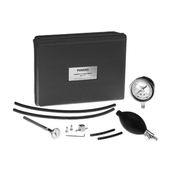
Calibration Kit for Room and Duct
Thermostats
Product Number
Caution Notation
Description
Item
1
Dial thermometer
2
Baumanometer
3
Dual scale pressure gauge 0 to 30 psi and 0 to 200 kPa
4
1/16-inch (1.6 mm) hex Allen wrench
5
1/4-inch (6.4 mm) OD plastic tubing, 2-3/4-inch (70 mm) long
6
1/4-inch (6.4 mm) OD plastic tubing plug
7
1/4-inch (6.4 mm) OD by 1/4-inch (6.4 mm) OD plastic by
1/8-inch (3.2 mm) NPT brass tee
8
3/16-inch (4.8 mm) ID rubber tubing, 12 inches (305 mm) long
9
Calibration Tool Kit (Part Number 832-178)
Dial Thermometer
Baumanometer
Item Number TB 239, Rev. 020
832-177
CAUTION:
This kit contains the equipment required to test pneumatic room and duct thermostats
and pneumatic devices such as valve or damper actuators or positioning relays.
Table 1 lists the items contained in the calibration kit.
Table 1. Calibration Kit Parts List.
Description
The dial thermometer is used to determine
the ambient temperature at the thermostat
sensing element.
The baumanometer is a squeeze bulb with
a restrictor type shut-off valve. It is used if
a source of air pressure is not available or
if a gradual air pressure change is required
to operate a pneumatic device such as a
valve or damper actuator.
Document No. 155-253P25
Equipment damage or loss of data may occur if you do not
follow procedures as specified.
Technical Bulletin
December 9, 2003
Quantity
Reference
1
Figure 1
1
Figure 2
1
Figure 3
1
Figure 4
2
Figure 5
2
Figure 6
1
Figure 7
2
Figure 8
1
TB 240
Figure 1. Dial Thermometer.
Figure 2. Baumanometer.
Siemens Industry, Inc.
TB 239
Advertisement
Table of Contents

Related Manuals for Siemens Powers 832-177


Summary of Contents for Siemens Powers 832-177
- Page 1 Figure 2. Baumanometer. Item Number TB 239, Rev. 020 Siemens Industry, Inc.
- Page 2 (Figure 2) or thermostat test port to the tee Figure 8. 3/16-Inch (4.8 mm) ID holding the gauge. Rubber Tubing. Assembly Figure 9. Pressure Gauge Assembly. CAUTION: Thermostats must be recalibrated whenever sensitivity is changed. Page 2 Siemens Industry, Inc.
-
Page 3: Table Of Contents
NOTE: Do not breathe on or touch the bi-metal coil, to avoid influencing the temperature reading. Figure 10. Typical Thermostat Details. Siemens Industry, Inc. Page 3... - Page 4 Alternately close and open nozzle by gently supply pressure exhaust valve seat pushing down the bi-metal Excessive air leakage Supply and return Connections are Reverse tubing connections from nozzle line connection interchanged or connection to port is incorrect Page 4 Siemens Industry, Inc.
- Page 5 This fluttering action will usually dislodge dirt from the throttling pin or brass exhaust valve seat. NOTE: Replacement parts are no longer available for this model. If this problem persists, replace the unit with a TH-192 Thermostat. Siemens Industry, Inc. Page 5...
-
Page 6: Th-182 Hc Heating-Cooling Thermostat
(48.2 kPa to 55.1 kPa at 22°C). The factory sensitivity setting is approximately 2-1/4 psi per degree Fahrenheit (27.9 kPa per degree Celsius). Any change in temperature setting or sensitivity of the heating side does not affect the cooling setting and vice versa. Page 6 Siemens Industry, Inc. - Page 7 The sensitivity of the slide must always be in contact with the center leg of the element. Recalibrate by rotating the nozzle. See Heating or Cooling Calibration Step 4. CAUTION: The element must be recalibrated whenever sensitivity is changed. Siemens Industry, Inc. Page 7...
- Page 8 This fluttering action will usually dislodge dirt from the throttling pin or brass exhaust valve seat. NOTE: Replacement parts are no longer available for these models. If this problem persists, replace the unit with a TH-192 Thermostat. Page 8 Siemens Industry, Inc.
-
Page 9: Th-182Dn And Th-182 Dnv Day-Night And Day-Night Vent Thermostats
(48.2 kPa to 55.1 kPa), turn the day nozzle counterclockwise. If greater than 7 psi to 8 psi (48.2 kPa to 55.1 kPa), turn the day nozzle clockwise. The thermostat day setting is now in calibration; proceed to Night Setting Calibration. Siemens Industry, Inc. Page 9... - Page 10 Only one bi-metal element with its nozzle and throttling pin will operate at a given time, and the choice of this operating element will be governed by the supply pressure. • Use the Pressure gauge assembly (Figure 9) to measure control pressure. Page 10 Siemens Industry, Inc.
- Page 11 This fluttering action will usually dislodge dirt from the throttling pin or brass exhaust valve seat. NOTE: Replacement parts are no longer available for this model. If this problem persists, replace the unit with a TH-192 Thermostat. Siemens Industry, Inc. Page 11...
-
Page 12: Direct Acting D Room Thermostat
11. Verify that the control pressure remains between 7 to 8 psi. 12. Replace the thermostat cover and tighten the two screws. The thermostat is now in calibration and can be set to the desired room temperature. Page 12 Siemens Industry, Inc. -
Page 13: D Day-Night Thermostats
10. Remove the D Adjustment Key and Pressure gauge assembly, and let pressure stabilize. 11. Verify that the control pressure remains between 7 to 8 psi. The Day Setting is now complete; proceed to Night Setting. Figure 14. D Day-Night Thermostat Details. Siemens Industry, Inc. Page 13... - Page 14 5. Move reset lever back to left. Thermostat will now control at night dial setting. Check calibration. 6. The thermostat is now in calibration. Test hose should be removed and test plug screwed in tightly. 7. Replace the thermostat cover and tighten the two cover screws. Page 14 Siemens Industry, Inc.
-
Page 15: Th-192 S Single Temperature Room Thermostat
2. Use a needle nose pliers to pull the limit stop tab (see Figure 15). 3. Rotate the limit stop to its new position. 4. Reposition between the setpoint cam gear teeth. Do not pull the limit stop any more than necessary to clear the gear teeth. Siemens Industry, Inc. Page 15... - Page 16 For one-pipe thermostats, the port is on the right side. • For two-pipe thermostats, the port is on the left side. CAUTION: If you use the wrong test port, thermostat damage can occur and result in replacement of the device. Page 16 Siemens Industry, Inc.
-
Page 17: Th192 Hc Heating/Cooling Room Thermostat
One turn increases the changeover point by about 3 psi (20 kPa). Turn on the supply pressure and recheck to verify the new changeover point. Figure 16. TH192 HC Thermostat Details. Siemens Industry, Inc. Page 17... - Page 18 NOTE: For TH192 HC thermostats, the test port is on the left side. CAUTION: If you use the wrong test port, thermostat damage can occur and result in replacement of the device. Page 18 Siemens Industry, Inc.
- Page 19 NOTE: For TH192 HC thermostats, the test port is on the left side. CAUTION: If you use the wrong test port, thermostat damage can occur and result in replacement of the device. Siemens Industry, Inc. Page 19...
-
Page 20: Th192 Dn Day/Night And Dnv Room Thermostat
One turn increases the changeover point by about 3 psi (20 kPa). Turn on the supply pressure and recheck to verify the new changeover point. Figure 17. TH192 DN and TH192 DNV Thermostat Details. Page 20 Siemens Industry, Inc. - Page 21 NOTE: For TH192 DN and DNV thermostats, the test port is on the left side. CAUTION: If you use the wrong test port, thermostat damage can occur and result in replacement of the device. Siemens Industry, Inc. Page 21...
- Page 22 NOTE: For TH192 DN and DNV thermostats, the test port is on the left side. CAUTION: If you use the wrong test port, thermostat damage can occur and result in replacement of the device. Page 22 Siemens Industry, Inc.
-
Page 23: Free Energy Band™ Th193 Hc Heating/Cooling Room Thermostat
Graduation closest to the rigid Graduation closest to the end of the bi-metal element minimum (MIN) end of the bi- metal element 4 psi/°F (50 kPa/°C) 1 psi/°F (12 kPa/°C) CAUTION: Thermostats must be recalibrated whenever sensitivity is changed. Siemens Industry, Inc. Page 23... - Page 24 To calibrate the TH193 HC Hesitation Thermostat, perform the following tasks in the order shown: 1. Calibrate the cooling element per Cooling Calibration. 2. Calibrate the heating element per Heating Calibration. 3. Adjust the dead band output pressure per Dead Band Output Pressure Adjustment. Page 24 Siemens Industry, Inc.
- Page 25 3. Set the heating and cooling dials to the desired set points. The dead band is between these two set points. 4. Replace the thermostat cover and tighten the two screws. The thermostat is now in calibration, and the setpoint can be changed to the desired room temperature. Siemens Industry, Inc. Page 25...
- Page 26 For one-pipe thermostats, the test port is on the right side. For two-pipe thermostats, the test port is on the left side. CAUTION: If you use the wrong test port, thermostat damage can occur and result in replacement of the device. Page 26 Siemens Industry, Inc.
-
Page 27: Free Energy Band™ Th193 Hc Hesitation Room Thermostat
Graduation closest to the rigid Graduation closest to the end of the bi-metal element minimum (MIN) end of the bi- metal element 4 psi/°F (50 kPa/°C) 1 psi/°F (12 kPa/°C) CAUTION: Thermostats must be recalibrated whenever sensitivity is changed. Siemens Industry, Inc. Page 27... - Page 28 To calibrate the TH193 HC Hesitation Thermostat, perform the following tasks in the order shown: 1. Calibrate the cooling element per Cooling Calibration. 2. Calibrate the heating element per Heating Calibration. 3. Adjust the dead band output pressure per Dead Band Output Pressure Adjustment. Page 28 Siemens Industry, Inc.
- Page 29 Allow the thermostat to stand for about five minutes to adjust to the new setting. 6. Repeat Cooling Calibration steps 6 through 8. The heating calibration is now complete. Proceed to Dead Band Output Pressure Adjustment. Siemens Industry, Inc. Page 29...
- Page 30 Information in this publication is based on current specifications. The company reserves the right to make changes in specifications and models as design improvements are introduced. Other product or company names mentioned herein may be the trademarks of their respective owners.© 2003 Siemens Industry, Inc. Your feedback is important to us. If you have Document No.
Need help?
Do you have a question about the Powers 832-177 and is the answer not in the manual?
Questions and answers