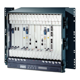
Cisco ONS 15454 Installation Instructions Manual
How to install cards and fiber-optic cable
Hide thumbs
Also See for ONS 15454:
- Hardware installation manual (516 pages) ,
- Troubleshooting manual (107 pages) ,
- Manual (88 pages)
Advertisement
Quick Links
Download this manual
See also:
Troubleshooting Manual
Install Cards and Fiber-Optic Cable
This chapter explains how to install the Cisco ONS 15454 cards and fiber-optic cable.
Before You Begin
This section lists the chapter procedures (NTPs). Turn to a procedure for applicable tasks (DLPs).
1.
2.
3.
4.
5.
6.
7.
8.
9.
10.
Only trained and qualified personnel should be allowed to install, replace, or service this equipment.
Warning
Statement 1030
Filler cards serve three important functions: they prevent exposure to hazardous voltages and
Warning
currents inside the chassis; they contain electromagnetic interference (EMI) that might disrupt other
equipment; and they direct the flow of cooling air through the chassis. Do not operate the system
unless all cards and faceplates are in place. Statement 156
78-17697-01
NTP-A15 Install the Common Control Cards, page
installing any other cards.
NTP-A16 Install Optical Cards and Connectors, page
NTP-A17 Install the Electrical Cards, page
NTP-A246 Install Ethernet Cards and Connectors, page
NTP-A274 Install the FC_MR-4 Card, page
NTP-A316 Install the Filler Cards, page
NTP-A247 Install Fiber-Optic Cables, page
cable on optical cards.
NTP-A245 Route Fiber-Optic Cables, page
NTP-A116 Remove and Replace a Card, page
and replace a card, including deleting the card from Cisco Transport Controller (CTC) and changing
an OC-N card without losing the card's provisioning.
NTP-A20 Replace the Front Door, page
procedure to replace the front door and ground strap after installing cards and fiber-optic cable.
C H A P T E R
2-2—Complete this procedure first before
2-7—Complete as needed.
2-10—Complete as needed.
2-11—Complete as needed.
2-13—Complete as needed.
2-15—Complete as needed.
2-16—Complete this procedure to install fiber-optic
2-19—Complete as needed.
2-20—Complete this procedure as needed to remove
2-21—If the front door was removed, complete this
Cisco ONS 15454 Procedure Guide, R8.0
2
2-1
Advertisement

Related Manuals for Cisco ONS 15454


Summary of Contents for Cisco ONS 15454
-
Page 1: Before You Begin
C H A P T E R Install Cards and Fiber-Optic Cable This chapter explains how to install the Cisco ONS 15454 cards and fiber-optic cable. Before You Begin This section lists the chapter procedures (NTPs). Turn to a procedure for applicable tasks (DLPs). - Page 2 Statement 94 Caution Always use the supplied ESD wristband when working with a powered ONS 15454. Plug the wristband cable into the ESD jack located on the lower-right outside edge of the shelf assembly. If protective clips are installed on the backplane connectors of the cards, remove the clips before Caution installing the cards.
- Page 3 NTP- A15 Install the Common Control Cards The XC card is compatible with most cards but does not support features new to Release 5.0 and Note greater. See the Cisco ONS 15454 Reference Manual for more information about XC card compatibility. Note For specific slot restrictions for a particular card, consult the card reference section for that card in the Cisco ONS 15454 Reference Manual.
- Page 4 Not supported with XCVT cards. Requires XC10G or XC-VXC-10G cards. STM64IO Short Reach and OC192/STM64 Any Reach (OC192-XFP cards) FC_MR-4 OC192 Not supported with XCVT cards. Requires XC10G or XC-VXC-10G cards. LR/STM64 LH ITU 15xx.xx Cisco ONS 15454 Procedure Guide, R8.0 78-17697-01...
- Page 5 DS1/E1-56 DS3-12 DS3-12E DS3N-12 DS3N-12E DS3XM-6 DS3XM-12 DS3/EC1-48 EC1-12 E100T-12 Not supported with the XC10G or XC-VXC-10G cards. E1000-2 Not supported with the XC10G or XC-VXC-10G cards. E100T-G E1000-2-G CE-100T-8 CE-1000-4 G1K-4 ML100-12 Cisco ONS 15454 Procedure Guide, R8.0 78-17697-01...
- Page 6 OC48 ELR 200 OC192 SR/STM64 IO 1310 OC192 IR/STM64 SH 1550 OC192 LR/STM64 LH 1550 OC192 LR/STM64 LH ITU 15xx.xx FC_MR-4 OC192SR1/ STM64IO Short Reach and OC192/STM64 Any Reach (OC192-XFP cards) MRC_12 MRC-2.5G-4 Cisco ONS 15454 Procedure Guide, R8.0 78-17697-01...
- Page 7 The laser is on when the card is booted and the safety key is in the on position (labeled 1). The port Warning does not have to be in service for the laser to be on. The laser is off when the safety key is off (labeled 0). Statement 293 Cisco ONS 15454 Procedure Guide, R8.0 78-17697-01...
- Page 8 Chapter 2 Install Cards and Fiber-Optic Cable NTP- A16 Install Optical Cards and Connectors Always use the supplied ESD wristband when working with a powered ONS 15454. Plug the wristband Caution cable into the ESD jack located on the lower-right outside edge of the shelf assembly.
- Page 9 OC-48 XC10G/XC-VXC-10G OC-48 OC-48 Refer to the card’s reference section in the “Optical Cards” chapter of the Cisco ONS 15454 Reference Manual for more information about slot and bandwidth restrictions. Open the card latches/ejectors. Step 2 Use the latches/ejectors to firmly slide the optical card along the guide rails until the card plugs into the Step 3 receptacle at the back of the slot.
- Page 10 Warning touch the backplane with your hand or any metal tool, or you could shock yourself. Statement 94 Always use the supplied ESD wristband when working with a powered ONS 15454. Plug the wristband Caution cable into the ESD jack located on the lower-right outside edge of the shelf assembly.
- Page 11 During this procedure, wear grounding wrist straps to avoid ESD damage to the card. Do not directly touch the backplane with your hand or any metal tool, or you could shock yourself. Statement 94 Cisco ONS 15454 Procedure Guide, R8.0 2-11...
- Page 12 Ethernet ports to intrabuilding or nonexposed wiring and cabling only. Always use the supplied ESD wristband when working with a powered ONS 15454. Plug the wristband Caution cable into the ESD jack located on the lower-right outside edge of the shelf assembly.
- Page 13 Allow the card to cool before touching any other part of it or before placing it in an antistatic bag. Statement 201 Always use the supplied ESD wristband when working with a powered ONS 15454. Plug the wristband Caution cable into the ESD jack located on the lower-right outside edge of the shelf assembly.
- Page 14 If you need to remove a GBIC or SFP/XFP, complete the “DLP-A470 Remove GBIC or Note SFP/XFP Devices” task on page 21-59. Step 7 Continue with the “NTP-A247 Install Fiber-Optic Cables” procedure on page 2-16. Stop. You have completed this procedure. Cisco ONS 15454 Procedure Guide, R8.0 2-14 78-17697-01...
- Page 15 Do not operate the system unless all cards and faceplates are in place. Statement 156 Always use the supplied ESD wristband when working with a powered ONS 15454. Plug the wristband Caution cable into the ESD jack located on the lower right outside edge of the shelf assembly and ensure the shelf assembly is properly grounded.
- Page 16 20-dB attentuator. Never connect a direct fiber loopback. Using fiber loopbacks causes irreparable damage to the OC192 LR/STM64 LH 1550 or OC192 LR/STM64 LH ITU 15xx.xx card. Cisco ONS 15454 Procedure Guide, R8.0 2-16 78-17697-01...
- Page 17 Never connect a direct, unattenuated fiber loopback. Using unattenuated fiber loopbacks causes irreparable damage to the OC192 IR/STM64 SH 1550 card. Always use the supplied ESD wristband when working with a powered ONS 15454. Plug the wristband Caution cable into the ESD jack located on the lower-right outside edge of the shelf assembly.
- Page 18 –21 dBm (FC) 0 dBm –22 dBm (GE) OC192SR1/STM64IO Short Reach –6 dBm –1 dBm –11 dBm –1 dBm (ONS-XC-10G-S1) OC192/STM64 Any Reach –6 dBm –1 dBm –11 dBm –1 dBm (ONS-XC-10G-S1) Cisco ONS 15454 Procedure Guide, R8.0 2-18 78-17697-01...
- Page 19 Stop. You have completed this procedure. NTP-A245 Route Fiber-Optic Cables Purpose This procedure describes how to route fiber-optic cables away from the ONS 15454 shelf, including installing fiber boots and fiber clips. Tools/Equipment None Prerequisite Procedures NTP-A247 Install Fiber-Optic Cables, page 2-16...
- Page 20 Close the fold-down front door when all fiber-optic cables in the front compartment are properly routed. Stop. You have completed this procedure. NTP-A116 Remove and Replace a Card Purpose This procedure removes and replaces all cards housed in the ONS 15454 shelf and rack. Tools/Equipment None...
- Page 21 2-1). Figure 2-1 Installing the Door Ground Strap Retrofit Kit Attach the other end of the ground strap to the longer screw on the fiber guide. Step 3 Attach the lock washer. Cisco ONS 15454 Procedure Guide, R8.0 2-21 78-17697-01...
- Page 22 Ground strap cable Step 6 Swing the door closed. The ONS 15454 comes with a pinned hex key tool for locking and unlocking the front door. Turn Note the key counterclockwise to unlock the door and clockwise to lock it.
Need help?
Do you have a question about the ONS 15454 and is the answer not in the manual?
Questions and answers