Table of Contents
Advertisement
Quick Links
Download this manual
See also:
Service Manual
Advertisement
Table of Contents

Related Manuals for Inter-m PT-9107S


Summary of Contents for Inter-m PT-9107S
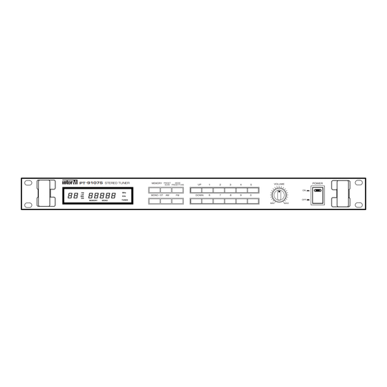
- Page 1 OC03 OC03 PT-9107S Stereo Tuner MEMORY POWER PT 9107S PRESET MODE STEREO TUNER VOLUME SCAN PRESET/TUNE MONO / ST DOWN MONO...
-
Page 2: Table Of Contents
5. Installation of the Speaker......................5 6. Applications of the Antenna ....................6 7. Warning..........................7 8. Applications ..........................8 9. Block Diagram........................9 10. Specifications........................10 OFFICE : 653-5 BANGHAK-DONG, DOBONG-KU, SEOUL, KOREA TEL : 82-2-2289-8140~8, FAX : 82-2-2289-8149 Home Page : http://www.inter-m.com E-mail : export@inter-m.com... -
Page 3: Unpacking And Installation
* Do not install this apparatus in a confined space such as a book case or similar unit. * The apparatus shall not be exposed to dripping or splashing and no objects filled with liquids, such as vases, shall be place on the apparatus. PT-9107S... -
Page 4: Features
- FM STEREO MUTE CIRCUIT This unit employed muting circuitry and eliminates noise when tuner is not tuned frequency in stereo state. - USE OF EMERGENCY BATTERY You can operate this by use of emergency battery for unexpected AC power failure. PT-9107S... -
Page 5: Front Panel Controls
7. MEMORY INDICATE (Number 10 Switch) This indicator is for memorizing the broadcasting frequency. 8. FM/AM BAND INDICATE (Number 4 Switch) This indicator is used for selecting AM or FM. 9. PRESET This indicator is display of the memory state. PT-9107S... - Page 6 When you press the UP/DOWN switch, MODE PRESET is increase and decrease by 1 channel. MODE TUNE is increase and decrease by 1 step. 13. ADDRESS SELECTOR SWITCH 20 kinds address are prepared and each address is accessible by this switches. PT-9107S...
-
Page 7: Rear Panel Controls
- AM TERMINAL: Connect the AM loop antenna. 8. FUSE COVER This fuse holder contain AC fuse, replace only with same type fuse when it is blown out. If it continuously low, stop replacing fuse and refer servicing to qualified personnel. PT-9107S... -
Page 8: Applications Of The Antenna
Fix one end of AM loop antenna single cable to the AM terminal and the other end to GND. - AM OUTDOOR ANTENNA Install the vinyl-coated cable to an outdoor place if the AM reception is not good enough. PT-9107S... -
Page 9: Warning
Mount antenna discharge unit as close as possible to where lead-in enters house. d Use jumper wire not smaller than No. 6 AWG (13.3 mm ) copper, or the equivalent, when a separate antenna-grounding electrode is used. See NEC Section 810-21(f). PT-9107S... -
Page 10: Applications
OUTPUT SUB OUT DUCK P.PWR DUCK P.PWR DC INPUT REC OUT INSERT CD PLAYER CASSETTE DECK PT-9107S OUTPUT CAUTION; TO REDUCE THE RISK OF ELE- AC INPUT FIXED VARIABLE CTRIC SHOCK, DO NOT REMOVE COVER. 230V 50Hz, 11W NO USER SERVICEABLE PARTS INSIDE. -
Page 11: Block Diagram
STEREO TUNER Block Diagram Block Diagram PT-9107S... -
Page 12: Specifications
AM .....................Mono Balance: 240mV (modul. 30%) Antenna Input ..........................FM: 75Ω ............................AM: Loop Ant. - GENERAL Power Source ...................AC 100V–240V, DC 24V 50/60Hz Power Consumption ........................11W Weight............................3.5kg Dimensions ....................482(W) 44(H) 280(D)mm * Specifications and design subject to change without notice for improvements. PT-9107S... - Page 13 NOTE...
- Page 14 NOTE...
- Page 15 MADE IN KOREA 9007983710...
Need help?
Do you have a question about the PT-9107S and is the answer not in the manual?
Questions and answers