Fisher Minute Mount 2 Mechanic's Manual
Hide thumbs
Also See for Minute Mount 2:
- Owner's manual (112 pages) ,
- Installation instructions manual (8 pages) ,
- Installation instructions (4 pages)

Related Manuals for Fisher Minute Mount 2


Summary of Contents for Fisher Minute Mount 2
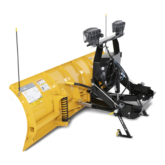
- Page 1 February 15, 2019 Lit. No. 41298, Rev. 01 SNOWPLOWS MECHANIC'S GUIDE SNOWPLOWS Featuring the Insta-Act Hydraulic System ® Isolation Module Light System CAUTION Read this manual before servicing the snowplow.
-
Page 3: Table Of Contents
TABLE OF CONTENTS INTRODUCTION ....................5 Electrical Schematic — 4-Port Module ............37 Recommended Tools ...................5 Hydraulic Schematic ..................42 Available Service Items ................5 Raise — Electrical ..................43 SAFETY ......................6 Raise — Hydraulic ..................44 Lower / Float — Electrical ................. 45 SPECIFICATIONS .....................9 Lower —... - Page 4 Lit. No. 41298, Rev. 01 February 15, 2019...
-
Page 5: Introduction
• Removable spring tool this manual carefully before attempting to service • Flat screwdriver (for replacing trip springs; PN 20043-1) the FISHER snowplow equipment covered by this guide. • Sockets and combination wrenches: • Hydraulic pressure test kit (PN 56686) 5/16"–7/8", 1-1/16", 1-1/8"... -
Page 6: Safety
SAFETY SAFETY DEFINITIONS Instruction Label WARNING Indicates a potentially hazardous situation Warning and Caution Label that, if not avoided, could result in death or serious personal injury. CAUTION Indicates a potentially hazardous situation that, if not avoided, may result in minor or moderate injury. - Page 7 SAFETY SAFETY PRECAUTIONS FUSES WARNING To prevent accidental movement of Improper installation and operation could cause The electrical and hydraulic systems contain the blade, always turn the control OFF personal injury, and/or equipment and property several automotive-style fuses. If a problem should whenever the snowplow is not in use.
- Page 8 SAFETY FIRE AND EXPLOSION BATTERY SAFETY TORQUE CHART WARNING CAUTION CAUTION Gasoline is highly fl ammable and gasoline Batteries normally produce explosive Read instructions before assembling. vapor is explosive. Never smoke while gases, which can cause personal injury. Fasteners should be fi nger tight until working on vehicle.
-
Page 9: Specifications
• Motor Amperage Draw = 100A at 1650 psi ± • Control – 7.5A 50 psi Hydraulic Fluid • Switched Accessory Lead Draw = 0.75A • FISHER ® EZ Flow Hydraulic Fluid to –40°F (–40°C) or other fl uid conforming to Military Specifi cation MIL-H-5606A, such as Mobil Aero HFA or Shell AeroShell ®... -
Page 10: Attaching/Detaching Snowplow From Vehicle
ATTACHING/DETACHING SNOWPLOW FROM VEHICLE HT Series™ ATTACH/DETACH DIAGRAM NOTE: After each use of the snowplow, reapply dielectric grease to the electrical plugs to maintain the protective coating on the terminals. NOTE: Multiplexed 2-plug systems are equipped with plug covers. Headgear Push Bar Pin Release Handle (raised) Headlamp Bracket... -
Page 11: Operational Test And Final Adjustments
A-frame should be parallel with the the fi ll hole. If additional fl uid is needed, fi ll the on you, you could be seriously injured. ground. reservoir with FISHER EZ Flow Hydraulic Fluid ® to –40°F (–40°C), or other fl uid conforming to 2. -
Page 12: System Overview
SYSTEM OVERVIEW VEHICLE LIGHTING CHECK 1. Verify the operation of all vehicle front lighting • Both vehicle and snowplow passenger-side If DRLs are in high or low beam fi lament when prior to connecting the snowplow harness. turn signal lamps should fl ash at the same the snowplow is attached, the corresponding time. -
Page 13: Headlamp Beam Aiming
SYSTEM OVERVIEW HEADLAMP BEAM AIMING Torque headlamp fasteners to 45 ft-lb once correct 4. Mark (or tape) the vertical centerline of e. Check functioning of any automatic visual aim is achieved. the snowplow headlamps and the vertical vehicle leveling systems and specifi c centerline of the vehicle on the screen. -
Page 14: Hydraulic Hose Routing
SYSTEM OVERVIEW – HYDRAULIC HOSE ROUTING HOSE ROUTING FOR HT Series™ BLADES To Lift Ram Base To PS To Lift To PS Ram Ram Rod Angle Ram To Lift Ram To DS To Lift Ram Base Angle Ram To DS Ram DS Ram PS Ram Lit. -
Page 15: Hydraulic Unit
SYSTEM OVERVIEW – HYDRAULIC UNIT Insta-Act ® HYDRAULIC UNIT The HT Series™ hydraulic unit has blade scrape lock circuitry built in. This feature is activated when the blade is in FLOAT. The HT Series blade is raised in approximately 4 seconds and angled side to side in approximately 3 seconds. - Page 16 SYSTEM OVERVIEW – HYDRAULIC UNIT SOLENOID CARTRIDGE VALVE IDENTIFICATION RELIEF VALVE IDENTIFICATION & LOCATION & LOCATION Pump Relief Valve PS Plowing DS Plowing Relief Valve Relief Valve Relief Valve Scrape Lock Solenoid Cartridge Valves Lit. No. 41298, Rev. 01 February 15, 2019...
-
Page 17: Hydraulic Component Installation
SYSTEM OVERVIEW – HYDRAULIC HYDRAULIC COMPONENT INSTALLATION Ram Seal Installation 2. Cycle through the control functions twice to Seal O-Ring Back-Up Ring remove the pressure in the hydraulic unit. Wear Ring 1. Lubricate O-rings before assembly. Wiper Gland 3. Slowly remove the breather from the top of the hydraulic unit. -
Page 18: Ht Series™ Controls
SYSTEM OVERVIEW – HT Series™ CONTROLS Power Indicator Light (red) ON/OFF Switch (emergency stop on side of control) ON/OFF Button (emergency stop) Joystick Control Hand-Held Control Lit. No. 41298, Rev. 01 February 15, 2019... -
Page 19: Hand-Held Control
HAND-HELD CONTROL WITH SECURITY GUARD™ SNOWPLOW ANTI-THEFT SYSTEM CONTROL OVERVIEW Function Time-Outs Each control is equipped with an ON/OFF switch WARNING and an indicator light to show when the control is To prevent accidental movement of the powered ON or OFF. The controls are powered by All control functions, except LOWER/FLOAT, time blade, always push the ON/OFF button the vehicle's battery, so your vehicle ignition (key) - Page 20 HAND-HELD CONTROL WITH SECURITY GUARD™ SNOWPLOW ANTI-THEFT SYSTEM Smooth Stop Function Description of Operation Press this button to raise the snowplow and The control automatically allows the blade to coast RAISE cancel the FLOAT mode. Function times out FLOAT Light to a stop when the button is released.
-
Page 21: Security Guard ™ Snowplow Anti-Theft System
HAND-HELD CONTROL WITH SECURITY GUARD™ SNOWPLOW ANTI-THEFT SYSTEM SECURITY GUARD System Activation & Establishing a 4-Digit Security Code 4. Once a 4-digit security code is established, NOTE: If the plow/vehicle electrical connection the SECURITY GUARD system will recognize is lost or disconnected, the SECURITY GUARD NOTE: The snowplow must be attached to the any control that has been programmed with system will reset, requiring any HT Series control... - Page 22 HAND-HELD CONTROL WITH SECURITY GUARD™ SNOWPLOW ANTI-THEFT SYSTEM Light Flash Indicators Additional Notes • The SECURITY GUARD system requires POWER – Red Function any HT Series™ control (other than the one Control is OFF with the assigned 4-digit security code) to enter the security code before the snowplow Solid On Control is ON and active...
-
Page 23: Joystick Control
JOYSTICK CONTROL WITH SECURITY GUARD™ SNOWPLOW ANTI-THEFT SYSTEM CONTROL OVERVIEW All half-ton snowplow controls come equipped Function Time-Outs WARNING with the SECURITY GUARD system. To use To prevent accidental movement of the this function, you must complete the "Activation" All control functions, except LOWER/FLOAT, time blade, always move the ON/OFF switch to process. - Page 24 JOYSTICK CONTROL WITH SECURITY GUARD™ SNOWPLOW ANTI-THEFT SYSTEM Smooth Stop FLOAT Light Function Description of Operation (green) Move the control lever toward the top of the The control automatically allows the blade to coast control body to raise the snowplow and cancel RAISE to a stop when the lever returns to center position.
-
Page 25: Security Guard ™ Snowplow Anti-Theft System
JOYSTICK CONTROL WITH SECURITY GUARD™ SNOWPLOW ANTI-THEFT SYSTEM SECURITY GUARD System Activation & Establishing a 4-Digit Security Code 4. Once a 4-digit security code is established, NOTE: If the plow/vehicle electrical connection the SECURITY GUARD system will recognize is lost or disconnected, the SECURITY GUARD NOTE: The snowplow must be attached to the any control that has been programmed with system will reset, requiring any HT Series control... - Page 26 JOYSTICK CONTROL WITH SECURITY GUARD™ SNOWPLOW ANTI-THEFT SYSTEM Light Flash Indicators Additional Notes • The SECURITY GUARD system requires POWER – Red Function any HT Series™ control (other than the one Control is OFF with the assigned 4-digit security code) to Solid On Control is ON and active enter the security code before the snowplow...
-
Page 27: Hand-Held Master Control For The Security Guard™ Snowplow Anti-Theft System
HAND-HELD MASTER CONTROL FOR THE SECURITY GUARD™ SNOWPLOW ANTI-THEFT SYSTEM UNIVERSAL CLEAR SECURITY WARNING IMPORTANT: The following steps must be NOTE: The only button that should be exposed performed using the Distributor Master is the LOWER button. All other buttons should To prevent accidental movement of the Control (PN 48800). -
Page 28: Theory Of Operation
THEORY OF OPERATION SNOWPLOW HYDRAULICS The HT Series™ snowplow hydraulic system Snowplow Daytime Running Lights The output of the vehicle high beam/low beam performs four blade movements. select switch is directed to the Isolation Module via the plug-in harness. When the snowplow is not Because Daytime Running Lamps (DRLs) are All functions require the vehicle ignition (key) attached to the vehicle, the signal passes through... - Page 29 THEORY OF OPERATION 3-PORT MODULE ELECTRICAL White Label Non-DRL Module • Activating a switched accessory wire (a • With the four headlamp relays shifted to the key-controlled power source) applies battery "snowplow" position, the vehicle high and (PN 29060) voltage to the VACC input of the module, low beams are now directed to the snowplow which energizes the coil of the control power headlamps via the vehicle and snowplow...
- Page 30 THEORY OF OPERATION 3-PORT MODULE ELECTRICAL Green Label DRL Module • Activating a switched accessory wire (a key- • Activating the turn signal applies voltage to the controlled power source) applies battery voltage module turn signal circuit input. A control circuit (PN 29070-1) to the VACC input of the module.
- Page 31 THEORY OF OPERATION 3-PORT MODULE ELECTRICAL Blue Label Module • Turning on the vehicle ignition switch provides • With the headlamp relays shifted to the 12V to the switched accessory wire, which in "snowplow" position, the vehicle high and (PN 29760-2) turn applies battery voltage to the VACC input low beams are now directed to the snowplow to the module at port C, pin C.
-
Page 32: Electrical & Hydraulic Schematics
ELECTRICAL & HYDRAULIC SCHEMATICS This section contains hydraulic and ELECTRICAL LEGEND HYDRAULIC LEGEND electrical schematics to help explain how the hydraulic unit performs the LINE, WORKING (MAIN) SPRING CROSSING WIRE different functions. A schematic is an abstract drawing showing the purpose LINES JOINING SOLENOID, SINGLE WINDING WIRE SPLICE... - Page 33 SYSTEM OVERVIEW – ELECTRICAL WIRING – 3-PORT MODULE CAUTION Factory Vehicle Harness On 2-plug electrical systems, Park/Turn plug covers shall be used Lamps whenever snowplow is disconnected. Vehicle battery Battery cable is 12V unfused source. Vehicle Headlamps Vehicle Battery Cable Vehicle Control Harness To Snowplow Control Vehicle Lighting...
-
Page 34: Electrical Schematic - 3-Port Module
ELECTRICAL SCHEMATIC – 3-PORT MODULE Snowplow Assembly Vehicle Battery Cable, 4-Receptacle Plow (End View) – Pump 1 – Red (Control Power) 1 – Red Control Motor – 2 – Red (Twisted with #3) 2 – Green 3 – Black (Twisted with #2) 3 –... - Page 35 LOW BEAM HEADLAMPS WITH SNOWPLOW CONNECTED TO VEHICLE (3-PORT MODULE) Snowplow Assembly Vehicle Battery Cable, 4-Receptacle Plow (End View) – Pump 1 – Red (Control Power) 1 – Red Control Motor – 2 – Red (Twisted with #3) 2 – Green 3 –...
- Page 36 HIGH BEAM HEADLAMPS WITH SNOWPLOW CONNECTED TO VEHICLE (3-PORT MODULE) Snowplow Assembly Vehicle Battery Cable, 4-Receptacle Plow (End View) – Pump 1 – Red (Control Power) 1 – Red Control Motor – 2 – Red (Twisted with #3) 2 – Green 3 –...
- Page 37 THEORY OF OPERATION 4-PORT MODULE ELECTRICAL Snowplow Headlamps With the snowplow attached, the Isolation Module is still inactive until either of the two following conditions are met: The vehicle parking lights are The Isolation Module acts as an electrical hub, turned ON or the vehicle ignition switch is turned automatically directing vehicle power to the appropriate vehicle or snowplow lighting devices,...
- Page 38 SYSTEM OVERVIEW – ELECTRICAL WIRING – 4-PORT MODULE CAUTION Factory Vehicle Harness On 2-plug electrical systems, Park/Turn plug covers shall be used Lamps whenever snowplow is disconnected. Vehicle battery Battery cable is 12V unfused source. Vehicle Headlamps Vehicle Battery Cable PN 29175 Adapter Vehicle Control Harness...
-
Page 39: Electrical Schematic - 4-Port Module
ELECTRICAL SCHEMATIC – 4-PORT MODULE Snowplow Assembly Vehicle Battery Cable, 4-Receptacle Plow (End View) – Pump 1 – Red (Control Power) 1 – Red Control Motor – 2 – Red (Twisted with #3) 2 – Green 3 – Black (Twisted with #2) 3 –... - Page 40 LOW BEAM HEADLAMPS WITH SNOWPLOW CONNECTED TO VEHICLE (4-PORT MODULE) Snowplow Assembly Vehicle Battery Cable, 4-Receptacle Plow (End View) – Pump 1 – Red (Control Power) 1 – Red Control Motor – 2 – Red (Twisted with #3) 2 – Green 3 –...
- Page 41 HIGH BEAM HEADLAMPS WITH SNOWPLOW CONNECTED TO VEHICLE (4-PORT MODULE) Snowplow Assembly Vehicle Battery Cable, 4-Receptacle Plow (End View) – Pump 1 – Red (Control Power) 1 – Red Control Motor – 2 – Red (Twisted with #3) 2 – Green 3 –...
-
Page 42: Hydraulic Schematic
HYDRAULIC SCHEMATIC ANGLE RIGHT ANGLE LEFT LIFT RAISE LOWER Quill Angle Relief Scrape Lock Angle Relief Pump Relief Pump Filter Draws Fluid on LOWER Return to Reservoir Lit. No. 41298, Rev. 01 February 15, 2019... -
Page 43: Raise - Electrical
RAISE – ELECTRICAL System Response Pump Motor 1. By activating the RAISE function on the cab control, the control sends a signal to the Plow Module to complete the ground path for the electrical circuit, activating the motor relay and solenoid cartridge valve S3. -
Page 44: Raise - Hydraulic
RAISE – HYDRAULIC ANGLE RIGHT ANGLE LEFT LIFT RAISE LOWER Quill Angle Relief Scrape Lock Angle Relief Pressure Return Pilot Line Pump Relief Pump Filter Draws Fluid on LOWER Return to Reservoir Lit. No. 41298, Rev. 01 February 15, 2019... -
Page 45: Lower / Float - Electrical
LOWER / FLOAT – ELECTRICAL System Response Pump Motor 1. By activating the LOWER function on the cab control, the control sends a signal to the Plow Module to complete the ground path for the electrical circuit, activating solenoid cartridge valve S1. -
Page 46: Lower - Hydraulic
LOWER – HYDRAULIC ANGLE RIGHT ANGLE LEFT LIFT RAISE LOWER Quill Angle Relief Scrape Lock Angle Relief Drawn from Tank Return Pilot Line Pump Relief Pump Filter Draws Fluid on LOWER Return to Reservoir Lit. No. 41298, Rev. 01 February 15, 2019... -
Page 47: Angle Right - Electrical
ANGLE RIGHT – ELECTRICAL System Response Pump Motor 1. By activating the angle right (R on the control face) function on the cab control, the control sends a signal to the Plow Module to complete the ground path for the electrical circuit, activating the motor relay and solenoid cartridge valve S2. -
Page 48: Angle Right - Hydraulic
ANGLE RIGHT – HYDRAULIC ANGLE RIGHT ANGLE LEFT LIFT RAISE LOWER Quill Angle Relief Scrape Lock Angle Relief Pressure Return Pilot Line Pump Relief Pump Filter Draws Fluid on LOWER Return to Reservoir Lit. No. 41298, Rev. 01 February 15, 2019... -
Page 49: Angle Left - Electrical
ANGLE LEFT – ELECTRICAL System Response Pump Motor 1. By activating the angle left (L on the control face) function on the cab control, the control sends a signal to the Plow Module to complete the ground path for the electrical circuit, activating the motor relay and solenoid cartridge valves S2 and S3. -
Page 50: Angle Left - Hydraulic
ANGLE LEFT – HYDRAULIC ANGLE RIGHT ANGLE LEFT LIFT RAISE LOWER Quill Angle Relief Scrape Lock Angle Relief Pressure Return Pilot Line Pump Relief Draws Fluid Pump Filter on LOWER Return to Reservoir Lit. No. 41298, Rev. 01 February 15, 2019... -
Page 51: Hold In Raise Position - Hydraulic
HOLD IN RAISE POSITION – HYDRAULIC Control: None ANGLE RIGHT ANGLE LEFT LIFT System Response RAISE LOWER Hydraulic fl uid is trapped in the rod end of the Quill lift ram by the internal check valve in solenoid cartridge valves S1. Angle Relief Scrape... -
Page 52: Striking An Object While Plowing - Hydraulic
STRIKING AN OBJECT WHILE PLOWING Blade Movement: Striking an Object Force applied Force applied While Plowing when pushing when backdragging ANGLE RIGHT ANGLE LEFT LIFT Control: None System Response: RAISE LOWER 1. Hydraulic fl uid is trapped in the base end of the Quill cylinders by the relief valves, the P/O check valve (PC1), and solenoid cartridge valve S2. - Page 53 STRIKING AN OBJECT WHILE PLOWING Blade Movement: Striking an Object Force applied Force applied While Plowing when pushing when backdragging ANGLE RIGHT ANGLE LEFT LIFT Control: None System Response: RAISE LOWER 1. Hydraulic fl uid is trapped in the base end of the Quill cylinders by the relief valves, the P/O check valve (PC1), and solenoid cartridge valve S2.
-
Page 54: Scrape Lock Open
SCRAPE LOCK OPEN (ALLOWS BLADE TO RAISE, FOLLOWING SURFACE CONTOUR) ANGLE RIGHT ANGLE LEFT LIFT RAISE LOWER Quill Angle Relief Scrape Lock Angle Relief Drawn from Reservoir Return to Reservoir Pump Relief Pump Filter Draws Fluid on LOWER Return to Reservoir Lit. -
Page 55: Troubleshooting Guide
TROUBLESHOOTING INTRODUCTION HOW TO USE THE TROUBLESHOOTING ELECTRICAL TESTING GUIDE All malfunctions of the HT Series™ snowplow Read and understand the electrical circuit Because of the relative complexity of the snowplow can be categorized as structural, electrical, or operation information in the Theory of Operation electrical and hydraulic systems, some conditions hydraulic. -
Page 56: Before You Begin
TROUBLESHOOTING BEFORE YOU BEGIN Before proceeding, or performing any tests, you must verify the following conditions: 1. Verify that the customer has accurately and d. Fuses are good. g. Hydraulic reservoir is fi lled to proper level completely described the problem. Check all with recommended fl... -
Page 57: Vehicle Headlamps
TROUBLESHOOTING VEHICLE HEADLAMPS Incorrect Operation or No Headlamps SOLUTIONS BASIC CHECKS DRL mode/automatic headlamp function. Fully understand OEM headlamp operation; refer to vehicle owner's manual. Correct Isolation Module kit installed for application. Verify per eMatch at www.fi sherplows.com. OEM lights operating correctly prior to installation. OEM headlamps must be fully operational for correct Isolation Module operation. -
Page 58: Snowplow Park/Turn Lamps
TROUBLESHOOTING SNOWPLOW PARK/TURN LAMPS* Incorrect Operation or No Park/Turn Lamps BASIC CHECKS SOLUTIONS OEM park/turn lamps working. Refer to vehicle owner's manual for fuse location and size. Harnesses connected between vehicle and snowplow (all). Harnesses must be connected for all snowplow and headlamp functions. Clean harness connectors. -
Page 59: Snowplow Drl Lamps
TROUBLESHOOTING SNOWPLOW DRL LAMPS* Incorrect Operation or No DRL Lamps BASIC CHECKS SOLUTIONS Fully understand OEM DRL operation. Refer to vehicle owner's manual for DRL operation. OEM headlamps and DRLs operating correctly. OEM headlamps must be fully operational for correct Isolation Module operation. OEM DRL fuse tests good. -
Page 60: Solenoid Coil Activation Test (Scat)
TROUBLESHOOTING SOLENOID COIL ACTIVATION TEST (SCAT) 4. Compare the SCAT results with the testing that should energize the coil(s). If switched NOTE: See the System charts on the following pages. ground is not present, go to the Control/ Overview – Controls section for details on Cable/Plow Module Test. - Page 61 TROUBLESHOOTING SOLENOID COIL ACTIVATION TEST (SCAT) 5. Connect the snowplow control into the 4-position Turn the snowplow control ON and perform NOTE: This MUX-plow diagnostic harness kit control connector either in the cab of the vehicle a SCAT. See the following chart for solenoid can be used with or without the snowplow or on the diagnostic harness.
-
Page 62: Individual Solenoid Coil Test
TROUBLESHOOTING SOLENOID COIL ACTIVATION TEST (SCAT) Off-Truck Testing 5. Connect the snowplow control into the 9. Perform any required repairs and retest as 4-position control connector on the diagnostic needed. Make sure to disconnect the power harness. source before removing the diagnostic 1. -
Page 63: Control/Cable/Plow Module Test
TROUBLESHOOTING CONTROL/CABLE/PLOW MODULE TEST CONDITION POSSIBLE CAUSE CORRECTIVE ACTION To Safely Handle PC Board: Make sure grille plugs between snowplow and truck are Snowplow is not connected. properly connected. With the vehicle switched accessory ON, test the 4-pin CAUTION connector inside the cab. If pin 1 does not have 12V and/or if pin 4 does not have ground, use the electrical schematic in Circuit board may be damaged by static Incomplete harness connection(s) or... -
Page 64: Motor And Motor Relay Test
TROUBLESHOOTING MOTOR AND MOTOR RELAY TEST 6. If switched 12V is present at the empty large 5. Check for switched 12V at the empty large WARNING motor relay terminal, replace the motor. motor relay terminal while activating any Keep 8' clear of the blade when it is being control function except LOWER. -
Page 65: Pump Pressure Test
TROUBLESHOOTING PUMP PRESSURE TEST POSSIBLE WARNING CONDITION CORRECTIVE ACTION CAUSE Keep 8' clear of the blade when it is being Pump relief valve may be out of adjustment. Turn relief valve clockwise raised, lowered, or angled. Do not stand 1/4 turn and retest pressure. Repeat until correct pressure (1650 ± 50 psi) between the vehicle and blade or directly in is obtained. -
Page 66: Blade Drop Speed Adjustment
TROUBLESHOOTING BLADE DROP SPEED ADJUSTMENT Fluid Level WARNING Keep 8' clear of the blade when it is being CAUTION raised, lowered, or angled. Do not stand Do not mix different kinds of hydraulic between the vehicle and blade or directly fl... - Page 67 Lit. No. 41298, Rev. 01 February 15, 2019...
- Page 68 Copyright © 2019 Douglas Dynamics, LLC. All rights reserved. This material may not be reproduced or copied, in whole or in part, in any printed, mechanical, electronic, fi lm, or other distribution and storage media, without the written consent of Fisher Engineering. Authorization to photocopy items for internal or personal use by Fisher Engineering outlets or snowplow owner is granted.
Need help?
Do you have a question about the Minute Mount 2 and is the answer not in the manual?
Questions and answers
I just had a Fisher HD2 with 8.5 foot straight blade installed by a fisher dealer on my 1995 F250 with a diesel. The problem is the plow headlights go on and off when the plow is hooked up and when not hooked up, now the truck headlights do the same thing Never had this problem with the old plow or with the headlights ever before
The intermittent operation of the plow headlights on a Fisher Minute Mount 2 could be caused by the following issues:
1. Loose or Faulty Electrical Connections – The system relies on electrical plugs to switch between vehicle and plow headlights. Check for loose, corroded, or damaged connectors in the wiring harness and plug-in module.
2. Defective Headlamp Module – The prewired plug-in module controls the switching between vehicle and plow headlights. If faulty, it may cause intermittent operation.
3. Grounding Issues – Poor ground connections can lead to inconsistent electrical performance. Inspect and ensure all grounds are securely fastened and free of corrosion.
4. Worn or Damaged Wiring – Inspect wiring for breaks, frays, or pinched areas that may cause intermittent contact.
5. Faulty Bulbs or Sockets – If the bulbs or sockets are damaged, it may result in flickering or intermittent operation.
6. Vehicle Daytime Running Lights (DRLs) Interference – Some vehicle DRLs may remain on with the plow attached, which could interfere with proper headlamp function.
Checking these areas systematically should help identify and resolve the issue.
This answer is automatically generated