Fisher Minute Mount 2 Owner's Manual
Snowplow
Hide thumbs
Also See for Minute Mount 2:
- Owner's manual (112 pages) ,
- Mechanic's manual (68 pages) ,
- Installation instructions manual (8 pages)

Related Manuals for Fisher Minute Mount 2


Summary of Contents for Fisher Minute Mount 2
- Page 1 November 1, 2016 Lit. No. 43894, Rev. 02 OWNER'S MANUAL Original Instructions CAUTION Read this document before operating or servicing snowplow. This manual supersedes all editions with an earlier date.
-
Page 3: Snowplow Owner Data Sheet
SNOWPLOW OWNER DATA SHEET Register your snowplow online at www.fisherplows.com Owner Name: ________________________________________________________________________ Date Purchased: ______________________________________________________________________ Dealer Name: ___________________________________________ Phone: ______________________ Dealer Address: ______________________________________________________________________ Vehicle Model/Year: ___________________________________________________________________ Snowplow Model/Year: _________________________________________________________________ Snowplow Type/Size: ___________________________________________ Weight: ___________ lb/kg Ballast: No ___ Yes ___ Amount ____________lb/kg Insta‑Act Hydraulic Unit Serial Number: ___________________________________________________... -
Page 5: Table Of Contents
TABLE OF CONTENTS Snowplow Owner Data Sheet .......3 Insta‑Act Hydraulic Units ........25 ® System Capacity ...........27 Preface ..............7 Pump Motor Specifications ......27 Safety ..............8 Cab Controls ............28 Vehicle Application Information ......15 Accessories and Options ........30 Ballast Requirements ........16 Attaching Snowplow to Vehicle ......34 Getting to Know Your Snowplow ......17 Operating Your Snowplow ........37 Minute Mount... - Page 6 TABLE OF CONTENTS Driving and Plowing on Snow and Ice .... 68 XtremeV™/XV2™ Cutting Edge Wear and Plowing Snow ..........69 Leveling Adjustment Procedure ..... 88 General Instructions .........70 Greasing XV2 Pivot Pin Hinge ......89 Hard Packed Snow ........70 Hydraulic System ..........
-
Page 7: Preface
This manual has been prepared to acquaint When service is necessary, bring your snowplow you with the safety information, operation, and to your local FISHER outlet. They know your maintenance of your new FISHER snowplow. snowplow best and are interested in your ®... -
Page 8: Safety
SAFETY SAFETY DEFINITIONS WARNING/CAUTION & INSTRUCTION LABELS WARNING Become familiar with and inform users about the Indicates a potentially hazardous warning/caution and serial number labels on the situation, that if not avoided, could result back of the blade and the instruction label on in death or serious personal injury. - Page 9 SAFETY Instruction Labels Warning/Caution Label Multiple Pinch Points Label XLS™ Blades Only (both sides) Lit. No. 43894, Rev. 02 November 1, 2016...
- Page 10 SAFETY Serial Number Label ZZZZZ YYMMDDLLXXXXZZZZZ zzzzz YYMMDDLLXXXXZZZZZ Code Definition 2‑Digit Year 2‑Digit Month 2‑Digit Day 2‑Digit Location Code XXXX 4‑Digit Sequential Number ZZZZZZ 5‑ or 6‑ Digit Blade Assembly PN Lit. No. 43894, Rev. 02 November 1, 2016...
- Page 11 (16 km/h). Do not exceed GVWR or GAWR including the blade and ballast. CAUTION The rating label is found on the driver-side vehicle door See your FISHER outlet for application ® cornerpost. recommendations. Lit. No. 43894, Rev. 02 November 1, 2016...
- Page 12 • Wear safety goggles to protect your eyes from FUSES battery acid, gasoline, dirt, and dust. The FISHER electrical and hydraulic systems • Avoid touching hot surfaces such as the ® contain several automotive blade‑style fuses. If engine, radiator, hoses, and exhaust pipes.
- Page 13 SAFETY FIRE AND EXPLOSION VENTILATION WARNING WARNING Gasoline is highly flammable and gasoline Vehicle exhaust contains lethal fumes. vapor is explosive. Never smoke while Breathing these fumes, even in low working on vehicle. Keep all open flames concentrations, can cause death. Never away from gasoline tank and lines.
- Page 14 SAFETY BATTERY SAFETY NOISE Airborne noise emission during use is below CAUTION 70 dB(A) for the snowplow operator. Batteries normally produce explosive gases, which can cause personal injury. VIBRATION Therefore, do not allow flames, sparks or lit tobacco to come near the battery. When Operating snowplow vibration does not exceed charging or working near a battery, always 2.5 m/s...
-
Page 15: Vehicle Application Information
VEHICLE APPLICATION INFORMATION • FISHER eMatch selection system is based CAUTION on available vehicle capacity for snowplow See your FISHER outlet/Web site ® equipment on a representative vehicle equipped for specific vehicle application with options commonly used for plowing and recommendations before installation. -
Page 16: Ballast Requirements
If ballast is required, it is important that it be as close to the tailgate as possible. secured properly behind the rear axle. A ballast retainer kit is available from your FISHER outlet ® (PN 62849). NOTE: The ballast retainer kit is for snowplow vehicles requiring ballast. -
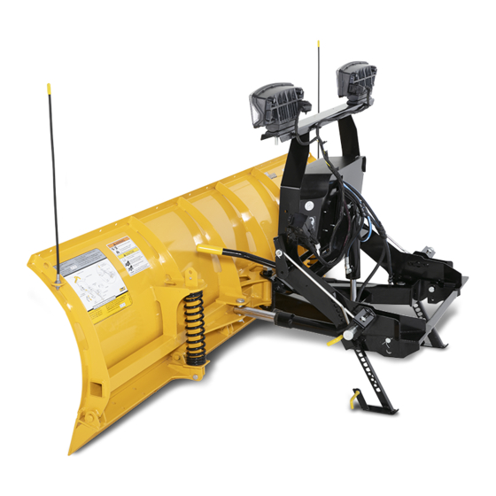
Page 17: Getting To Know Your Snowplow
Insta-Act Hydraulic Unit quickest and easiest mounting system available, the Minute Mount 2 system is twice the mount Release because it takes half the time. The Minute Mount 2 Vehicle Handle system should be installed according to the Headgear Mount instructions supplied. -
Page 18: Blades
The blade is curved to pick up snow and cast it aside smoothly—rolling snow instead of pushing it. This action allows you to move more snow faster, The FISHER difference—the integral trip‑edge ® using less power, saving fuel, and reducing wear design—is incorporated into all Minute Mount... -
Page 19: Ht Series™/Sd Series/Hd2
GETTING TO KNOW YOUR SNOWPLOW HT Series™ HD2™ As truck manufacturers reduce vehicle weight to Designed for today's snow plowing professional, increase fuel efficiency, plowers struggle to find a the HD2 snowplow is available in 7'6", 8', 8'6", rugged, hard‑working snowplow that matches their and 9' widths and is constructed of heavy‑duty 1/2-ton truck specifications. -
Page 20: Hdx™/Mc Series/Xtremev
GETTING TO KNOW YOUR SNOWPLOW HDX™ MC Series The ultimate in straight blade performance and Designed for trucks in the 17,000–27,500 GVW reliability, the stainless steel HDX snowplow gives range, these 9' and 10' snowplows are built for you a whole new way to attack winter. Built for the municipalities and contractors who need to clear business of plowing, this rugged snowplow will parking lots, narrow streets, and intersections. -
Page 21: Xv2™/Xls™ Series
GETTING TO KNOW YOUR SNOWPLOW XV2™ XLS™ With its deep curl tapered‑wing design, the From an 8' retracted to a 10' expanded straight XV2 blade takes the popular XtremeV™ wing blade, to a scoop width of nearly 9', the XLS design to another level. -
Page 22: A-Frame/T-Frame
25°, providing excellent snow displacement. The heavy 1" pivot The headgear also provides the mounting bolt is shear‑proof under normal operation, framework for the FISHER Insta‑Act hydraulic ® ®... -
Page 23: Weights Table
GETTING TO KNOW YOUR SNOWPLOW Weights: Off-Truck Assembly with Blade Size Blade Assembly Wt (lb) Wt (kg) Size Blade Assembly Wt (lb) Wt (kg) 7‑1/2' HT Series™ Snowplow (MS) 7‑1/2' XV2™ Snowplow 6'‑9" SD Snowplow (MS) 8‑1/2' XV2 Snowplow 7‑1/2' SD Snowplow (MS) 9‑1/2' XV2 Snowplow... -
Page 24: Mount Kits
GETTING TO KNOW YOUR SNOWPLOW MOUNT KITS INTENSIFIRE™ SNOWPLOW HEADLAMPS Fisher Engineering has designed a mount kit for most vehicles. Due to the differences between WARNING vehicle models, the kits are not interchangeable. Your vehicle must be equipped with snowplow headlamps and directional lights. -
Page 25: Insta-Act ® Hydraulic Units
GETTING TO KNOW YOUR SNOWPLOW Insta-Act HYDRAULIC UNITS The HT Series™ hydraulic unit has built‑in blade ® scrape lock circuitry to resist the tendency of a snowplow to "float up" while plowing deep snow or The Insta‑Act hydraulic unit delivers fast, uniform stacking snow into piles. - Page 26 GETTING TO KNOW YOUR SNOWPLOW The Insta‑Act hydraulic unit's angling gives you The XLS blade is raised in approximately ® full control of the snowplow from within the cab. 2 seconds and angled side to side in approximately Hydraulic rams hold the blade at a desired angle. 2 seconds.
-
Page 27: System Capacity
GETTING TO KNOW YOUR SNOWPLOW System Capacity XtremeV™ and XV2™ Blades 12 V DC with +/– Connection • Insta‑Act Unit Reservoir ....1‑3/4 quarts ® 2200–2300 psi Pump Relief Valve • Insta‑Act System Total ..2‑3/8 to 2‑3/4 quarts 4550–4650 psi Plowing Relief Valve 3650–3750 psi Back Dragging Relief Valve Pump Motor Specifications 4.5"... -
Page 28: Cab Controls
The ON/OFF switch on the cab control allows power indicator light will turn OFF. you to turn OFF the control and prevent blade movement even when the ignition switch is ON. FISHER snowplows come equipped with one ® The control ON/OFF switch serves as an of two special controls: the Fish‑Stik... - Page 29 GETTING TO KNOW YOUR SNOWPLOW Snowplow Controls with FLEET FLEX System Power Indicator Light (red) ON/OFF Switch (Emergency Stop) ON/OFF Button (Emergency Stop) Fish-Stik ® Joystick Control Hand-Held Control Lit. No. 43894, Rev. 02 November 1, 2016...
-
Page 30: Accessories And Options
ACCESSORIES AND OPTIONS BLADE WINGS Blade wings extend out and forward, increasing the length and improving the overall operating performance of your snowplow. STEEL DEFLECTOR Keeps fluffy snow from flowing over the top of the SnoFoil ASSEMBLY ® blade. Easily installed and attractively priced. The SnoFoil accessory improves visibility and RUBBER DEFLECTOR plowing efficiency by deflecting light snow away... - Page 31 ACCESSORIES AND OPTIONS REPLACEABLE CUTTING EDGES UHMW Polymer Carbon Steel These 1"‑thick cutting edges made of durable, lightweight polymer absorb much of the shock and vibration when the blade encounters rough Cutting edges made of high‑carbon steel bolt surfaces. to the base angle for maximum blade life. Depending on the blade series, cutting edges are Rubber 3/8", 1/2", and 5/8"...
- Page 32 Minute Mount 2 SYSTEM SKID PLATES ® abrasive surfaces (hard pack, gravel). These off‑season inserts for the Minute Mount 2 WEAR/CURB SHOE KIT system pushplates offer protection by filling and covering the receiver portion of the pushplates. These shoes offer two types of wear protection.
- Page 33 This long lasting plow cover is constructed of There's also a quart of FISHER EZ Flow hydraulic heavy duty nylon with a gathered elastic band fluid and a knit cap to keep your ears warm while sewn into the bottom edge for a tight, weather‑...
-
Page 34: Attaching Snowplow To Vehicle
ATTACHING SNOWPLOW TO VEHICLE ATTACHING SNOWPLOW NOTE: Use dielectric grease to prevent corrosion on all connections. WARNING Attaching Steps: Keep 8' clear of the blade when it is being raised, lowered, or angled. Do not stand between vehicle and blade or directly in 1. - Page 35 ATTACHING SNOWPLOW TO VEHICLE blade, stand in front of headgear on driver's Headgear side and push headlamp bracket. Jack (fully raised) HT Series™: Using headgear push bar, push headgear toward vehicle to allow connecting Headlamp pins to fully engage pushplates. See following Bracket page for illustration.
- Page 36 ATTACHING SNOWPLOW TO VEHICLE Attach HT Series™ Blade Headgear Push Bar Pin Release Handle (raised) Headlamp Bracket Jack Lock Attachment Jack (raised) Pin Release Handle (lowered) Pushplate Connecting Pin Jack Lock Jack (lowered) Lit. No. 43894, Rev. 02 November 1, 2016...
-
Page 37: Operating Your Snowplow
OPERATING YOUR SNOWPLOW Fish-Stik HAND-HELD CONTROL ® FLOAT Light Power Indicator (green) Light (red) FLOAT ON/OFF WARNING To prevent accidental movement of the RAISE blade, always push the ON/OFF button ON/OFF Button to switch the control OFF whenever (Emergency Stop) the snowplow is not in use. - Page 38 OPERATING YOUR SNOWPLOW Automatic Shutdown Function Description of Operation Press this button to raise the blade and The control will automatically turn OFF after being cancel FLOAT mode. Function times out RAISE idle for 20 minutes. To reactivate the control after after 3.0 (straight blades), 4.0 (XtremeV™, XV2™) or 3.5 (XLS™) seconds.
- Page 39 OPERATING YOUR SNOWPLOW Scoop/Retract Blade Position Function Description of Operation XtremeV, XV2, and XLS Blades Straight blades: Press this button to angle the blade to the left. FLOAT ON/OFF All others: With wings in a straight line, press the L button to move both wings (Angle to the angle left position.
- Page 40 OPERATING YOUR SNOWPLOW Wing Positions Function Description of Operation XtremeV™, XV2™, and XLS™ Blades Press this button on the left side of the control to move the left wing. The first time the button is pressed after the control is turned ON or another function is used, the wing will extend.
- Page 41 OPERATING YOUR SNOWPLOW JOYSTICK CONTROL FLOAT Light Power Indicator (green) Light (red) WARNING To prevent accidental movement of the ON/OFF FLOAT blade, always move the ON/OFF switch to OFF whenever the snowplow is not in use. RAISE The power indicator light will turn OFF. SCOOP RETRACT ON/OFF Switch...
- Page 42 OPERATING YOUR SNOWPLOW Function Time-Outs Smooth Stop/Soft Stop All control functions, except LOWER/FLOAT, time The control automatically allows the blade to coast out (stop) automatically after a period of time. This to a stop when the lever returns to center position. is to limit the amount of electrical energy required This results in smoother operation, reduces the from the vehicle.
- Page 43 OPERATING YOUR SNOWPLOW Control Functions Function Description of Operation Move the control lever toward the top of the Raise, Lower, Float, Angle control body to raise the blade and cancel RAISE the FLOAT mode. Function times out after 3.0 (straight blades), 4.0 (XtremeV™, Moving the control lever straight up and down or XV2™) or 3.5 (XLS™) seconds.
- Page 44 OPERATING YOUR SNOWPLOW Scoop/Retract Blade Position Function Description of Operation XtremeV, XV2, and XLS Blades Straight blades: Move the control lever straight to the left to angle the blade left. Moving the control lever from the center position All others: With wings in a straight line, toward the word SCOOP or RETRACT on the face move the control lever straight to the of the control body will cause both wings to move...
- Page 45 OPERATING YOUR SNOWPLOW Wing Positions Function Description of Operation XtremeV™, XV2™, and XLS™ Blades Move the control lever toward the left side of LOWER on the control face to move Moving the control lever from the center position the left wing. The first time the lever is toward the words WING IN/OUT, on either side of moved into the slot after the control is turned ON or another function is used,...
-
Page 46: Fleet Flex Electrical System
OPERATING YOUR SNOWPLOW FLEET FLEX ELECTRICAL SYSTEM This section provides more information about each feature, as well as instructions on how to enable or disable them. These features are offered to Your Minute Mount 2 system snowplow comes ® give you the ability to secure your snowplow and standard with user‑controlled programmable customize your plowing experience. -
Page 47: Security Guard™ System
OPERATING YOUR SNOWPLOW SECURITY GUARD™ System 1. Turn the vehicle ignition switch to the "ON" or "ACCESSORY" position. (It is not necessary to start the vehicle.) Activation & Establishing a 4-Digit Security Code 2. Verify that the control power indicator is OFF. If the power indicator light is red, the control is NOTE: The snowplow must be attached to ON. - Page 48 OPERATING YOUR SNOWPLOW Once you have entered your 4‑digit Manual Unlock security code, the FLOAT light will stop flashing and the power indicator light will If the SECURITY GUARD System is activated turn OFF. This indicates that your 4‑digit and you are using a control with a different 4‑digit security code is entered and stored in the code than the established security code, you will SECURITY GUARD™...
- Page 49 OPERATING YOUR SNOWPLOW 5. After entering the correct security code, the 3. Move the ON/OFF switch to the "OFF" power indicator light will change from flashing position or push the ON/OFF button to switch rapidly to a solid light to indicate the snowplow the control OFF.
- Page 50 OPERATING YOUR SNOWPLOW Light Flash Indicators System recognizes that a control with the same security code is attached, and does not require a manual unlock to activate the POWER – Red Function snowplow. The system will recognize the Control is OFF control as "safe"...
-
Page 51: Smooth Stop/Soft Stop
OPERATING YOUR SNOWPLOW Smooth Stop/Soft Stop Enable/Disable Procedure 1. Turn the vehicle ignition switch to the "ON" or Smooth stop, or "soft" stop, is a feature that allows "ACCESSORY" position. (It is not necessary the blade to coast to a stop when the button/lever to start the vehicle.) is released. -
Page 52: One-Touch Float
OPERATING YOUR SNOWPLOW One-Touch FLOAT 2. Verify that the control power indicator is OFF. If the power indicator light is red, the control One‑touch FLOAT immediately activates the is ON. Move the ON/OFF switch to "OFF" or FLOAT mode and releases the blade to the push the ON/OFF button to turn the control ground, without having to hold the button or lever OFF. -
Page 53: V-Plow Blade Positions
OPERATING YOUR SNOWPLOW V-PLOW BLADE POSITIONS Straight Blade NOTE: For best road clearance during Move both wings to form a straight blade for wide transport, place the blade halfway between path plowing or "stacking" snow. the straight and retracted (vee) positions. The scoop position is NOT RECOMMENDED during transport. - Page 54 OPERATING YOUR SNOWPLOW Angled Blade Retracted (Vee) Blade Move one wing "OUT" and the other wing "IN" to Move both wings "IN" toward the vehicle for initial form an angled blade in either direction for general break through plowing and plowing paths or plowing and widening.
- Page 55 OPERATING YOUR SNOWPLOW Scoop Blade Dogleg Blade Move both wings "OUT" away from the vehicle Move one wing to straight blade position and the to form a scoop to "carry" snow with minimum other "OUT" to scoop blade position for clean up spilloff.
-
Page 56: Xls Blade Positions
OPERATING YOUR SNOWPLOW XLS™ BLADE POSITIONS Retracted Blade The XLS snowplow can be used in four basic Move both wings "IN" to form a standard straight plowing positions. blade. NOTE: Always transport the XLS snowplow with both wings fully retracted. Lit. - Page 57 OPERATING YOUR SNOWPLOW Scoop Blade Dogleg Blade Move both wings "OUT" and ahead of the vehicle Move one wing to extended blade position and the to form a scoop to "carry" snow with minimum other "OUT" to scoop blade position for clean up spilloff.
- Page 58 OPERATING YOUR SNOWPLOW Extended Blade Move both wings "OUT" straight for an extra‑wide blade for clearing large areas. Lit. No. 43894, Rev. 02 November 1, 2016...
-
Page 59: Snowplow Headlamp Check
OPERATING YOUR SNOWPLOW SNOWPLOW HEADLAMP CHECK Aiming the Headlamps With all electrical plugs connected, check the • Aim the snowplow headlamps with the operation of vehicle and snowplow headlamps. snowplow mounted and raised in the transport position. See "Aiming Headlamp Beams" in the Maintenance section for instructions. -
Page 60: Antiwear Shoe Adjustment
OPERATING YOUR SNOWPLOW ANTIWEAR SHOE ADJUSTMENT Adjustment Procedure WARNING Blade can drop unexpectedly. Place blade on jack stands. Failure to do so could result in serious personal injury. Shoe CAUTION Holder Do not store unused spacers on top of the shoe holder. - Page 61 OPERATING YOUR SNOWPLOW 1. Raise the blade 1' off the road surface, turn 5. Reinstall the linchpin. the control OFF and, from in front of the blade, place jack stands under the cutting edge. 6. Turn the control and vehicle ignition ON. Raise the blade slightly from the jack stands.
-
Page 62: Hydraulic System
OPERATING YOUR SNOWPLOW HYDRAULIC SYSTEM set limits, the relief valve opens allowing fluid to escape, and the ram retracts. The Insta‑Act hydraulic unit's valve manifold ® For hydraulic fluid type and filling instructions, see includes relief valves to prevent damage to the "Annual Fluid Change"... -
Page 63: Blade Drop Speed Adjustment
OPERATING YOUR SNOWPLOW BLADE DROP SPEED ADJUSTMENT The quill in the valve manifold adjusts the blade drop speed. WARNING 1. Lower the blade to the ground before making Keep 8' clear of the blade when it is being the adjustment. raised, lowered, or angled. -
Page 64: Scrape Lock Adjustment - Ht Series
OPERATING YOUR SNOWPLOW SCRAPE LOCK ADJUSTMENT 5. Replace the hydraulic unit cover. XtremeV™, XV2™, and XLS™ units: Follow the instructions below to increase the Replace the cover and reinstall the top and pressure setting of the HT Series™ blade's scrape bottom cover retainers. - Page 65 OPERATING YOUR SNOWPLOW 5. Using a "Tee" fitting, install a 500–600 psi 6. Retighten the breather/fill plug. gauge in the lift ram base hose. Reconnect the snowplow battery cable to the Pressure vehicle battery cable. Gauge To Lift Ram Base 8.
- Page 66 OPERATING YOUR SNOWPLOW 10. If the hydraulic pressure reading is less than 14. Loosen the breather/fill plug slowly to relieve 350 psi, increase the pressure by turning the any pressure in the reservoir. scrape lock valve stem clockwise 1/4 turn and retest pressure.
-
Page 67: Transporting Snowplow
OPERATING YOUR SNOWPLOW TRANSPORTING SNOWPLOW NOTE: Always transport the XLS™ snowplow with both wings fully retracted. WARNING 1. Completely raise the blade. Position blade so it does not block headlamp beam. 2. Adjust the blade height for maximum Do not change blade position while snowplow headlamp illumination. -
Page 68: Driving And Plowing On Snow And Ice
OPERATING YOUR SNOWPLOW DRIVING AND PLOWING ON SNOW Here are some tips for driving in these conditions: AND ICE • Drive defensively. CAUTION • Do not drink, then drive or plow snow. Drinking then driving or plowing is very • Plow or drive only when you have good dangerous. -
Page 69: Plowing Snow
OPERATING YOUR SNOWPLOW PLOWING SNOW CAUTION Never stack snow with the blade angled. WARNING This could damage the snowplow or the vehicle bumper. Never plow snow with head out the vehicle window. Sudden stops or protruding objects could cause personal injury. CAUTION Plowing speed should not exceed 10 mph CAUTION... -
Page 70: General Instructions
OPERATING YOUR SNOWPLOW General Instructions Hard-Packed Snow 1. Before plowing, make sure you know of any 1. On blades equipped with shoes, raise the obstructions hidden beneath the snow such as antiwear shoes so that the cutting edge bumper stops in parking lots, curbs, sidewalk comes into direct contact with the pavement. -
Page 71: Clearing Driveways
OPERATING YOUR SNOWPLOW Clearing Driveways 2. Bite into the edges using only a partial blade width until the job is cut down to size for full blade plowing. 1. Head into the driveway with the blade angled and plow the snow away from any buildings. Rule of thumb: Widen the driveway by rolling snow away from 6"... -
Page 72: Clearing Parking Lots
OPERATING YOUR SNOWPLOW Clearing Parking Lots PARKING WITH SNOWPLOW ATTACHED 1. Clear areas in front of buildings first. With the blade raised, drive up to the building. Drop the WARNING blade and "back drag" the snow away from the building. When snow is clear of the buildings, Lower the blade when the vehicle is turn the vehicle around and push snow away parked. -
Page 73: Detaching Snowplow From Vehicle And Storage
DETACHING SNOWPLOW FROM VEHICLE & STORAGE DETACHING SNOWPLOW NOTE: The blade must be in the straight position when attaching or detaching the snowplow. WARNING Keep 8' clear of the blade when it is being During the off‑season, the control can be removed. raised, lowered, or angled. - Page 74 DETACHING SNOWPLOW FROM VEHICLE & STORAGE 3. Stand in front of blade. While pushing headgear Headgear toward vehicle with left hand, push pin release Jack handle down to disengage connecting pins. (fully raised) Make sure connecting pins are fully retracted. If unable to push headgear from in front of blade, Headlamp stand in front of headgear on the driver's side...
- Page 75 DETACHING SNOWPLOW FROM VEHICLE & STORAGE Detach HT Series™ Blade NOTE: Place electrical plugs in storage position. The driver-side and center plug on 3-plug electrical systems are joined for storage. The passenger-side and 2-plug systems are equipped with plug covers. Headgear Push Bar Headlamp Bracket Pin Release...
- Page 76 DETACHING SNOWPLOW FROM VEHICLE & STORAGE STORAGE Your snowplow is designed to be moved into a storage location using your vehicle and plow attaching system. For easier attaching of the snowplow, store it on a hard, level surface. Lit. No. 43894, Rev. 02 November 1, 2016...
-
Page 77: Maintenance
MAINTENANCE AIMING HEADLAMP BEAMS 3. Prepare vehicle for headlamp aim or inspection. Before checking beam aim, the inspector will: Tighten headlamp fasteners to 45 ft‑lb once correct visual aim is achieved. a. Remove ice or mud from under fenders. 1. Place vehicle on a level surface 25 feet b. - Page 78 MAINTENANCE 4. Mark (or tape) the vertical centerline of 5. Align the top edge of the high‑intensity zone the snowplow headlamps and the vertical of the snowplow lower beam below the centerline of the vehicle on the screen. Mark horizontal centerline and the left edge of the the horizontal centerline of the snowplow high‑intensity zone on the vertical centerline headlamps on the screen (distance from...
-
Page 79: Preseason Check
MAINTENANCE PRESEASON CHECK • Drain hydraulic system and refill with recommended hydraulic fluid. For hydraulic fluid type and filling instructions, see "Annual WARNING Fluid Change" under "Hydraulic System" in Lower the blade when the vehicle is this section of the manual. parked. -
Page 80: Postseason Maintenance
See your authorized • Any ballast material (such as sand and FISHER outlet for service. ® blocks) must be solidly secured to the vehicle preventing it from moving under harsh plowing NOTE: Coat all electrical connections with conditions. -
Page 81: Maintenance And Adjustment
Not doing so will make operation of the mount difficult and possibly damage components. Your FISHER snowplow is designed for rugged, ® dependable service. However, like the vehicle on which it is mounted, it needs regular care and maintenance. -
Page 82: Hdx™ Adjustable Attack Angle
MAINTENANCE HDX™ ADJUSTABLE ATTACK ANGLE Blade Adjustment 1. To adjust the attack angle, loosen (DO NOT CAUTION REMOVE) the lower quadrant 1" locknuts. If the snowplow is not attached to the Remove the upper quadrant 3/4" locknuts, vehicle, lean the headgear forward. Failure washers, and cap screws. - Page 83 MAINTENANCE 2. Align the desired attack angle holes in the 3. Reinstall the upper quadrant fasteners on both quadrant and blade as shown. sides of the quadrant as shown. 65° 55° & 75° 55° 3/4" Cap 65° Screw 3/4" Locknut 75°...
- Page 84 MAINTENANCE 4. Torque upper and lower fasteners as shown: CAUTION Servicing the trip springs without special Torque 3/4" fasteners tools and knowledge could result in to 269 ft-lb personal injury. See your authorized outlet for service. 5. If the attack angle has been changed to or from 55°, the lower mounting position of the springs must be changed as shown.
-
Page 85: Accessories Adjustment
MAINTENANCE Accessories Adjustment 6. A special spring removal tool (20043) must be used to safely make this adjustment. NEVER ATTEMPT SPRING REMOVAL WITHOUT The blade guides must be adjusted to THE SPECIAL TOOL. Follow the instructions match the attack angle. Remove the in the spring tool kit for proper tool usage. -
Page 86: Leveling The Hdx Or Hd2™ A-Frame
MAINTENANCE LEVELING THE HDX™ OR HD2™ Find the appropriate range for your attack angle setting, and verify that the headgear is connected A-FRAME to the corresponding A‑frame hole. After adjusting the attack angle, it might be necessary to level the A‑frame. Measure the distance from the center of the connecting pin hole to the ground. -
Page 87: Greasing The Hdx Pivot Beam
MAINTENANCE GREASING HDX PIVOT BEAM HDX™ Snowplow Attack Angle Mount Height (in) A-Frame Hole 1. Using a rubber‑tipped seal‑off coupler, apply 16.75–18.25 good quality multipurpose grease through the 75° 15.25–16.75 Middle two grease points in the rear of the pivot beam. 13.75–15.25 Bottom 15.75–17.25... -
Page 88: Leveling Adjustment Procedure
MAINTENANCE XtremeV™ & XV2™ CUTTING EDGE T-Frame WEAR AND LEVELING ADJUSTMENT PROCEDURE Once the snowplow has been installed on the vehicle in the correct configuration, a fine Push adjustment can be done to bring the blade cutting Front Assembly Fasteners edges into full contact with the ground. -
Page 89: Greasing Xv2 Pivot Pin Hinge
MAINTENANCE GREASING XV2™ PIVOT PIN HINGE 5. Raise and lower the blade several times. The cutting edge should contact the level surface across the full length of the cutting edge. Using a rubber‑tipped seal‑off coupler, apply a good quality multipurpose grease at the five 6. -
Page 90: Hydraulic System
MAINTENANCE HYDRAULIC SYSTEM 2. For straight blades, any angle will do, but for XtremeV, XV2, and XLS blades, move the blade wings to the fully retracted (vee) position. Fluid Level 3. Activate the control FLOAT function and CAUTION manually collapse the lift ram all the way. Do not mix different kinds of hydraulic fluid. - Page 91 MAINTENANCE 6. HT Series™ Blades: Fill the reservoir to For fluid recommendations see "Annual Fluid within 2-1/2" from the top of the fill hole and Change" in this section. replace the fill plug. XtremeV™, XV2™, XLS™, and other Straight Blades: Fill the reservoir to the top of the fill hole and replace the fill plug.
-
Page 92: Annual Fluid Change
MAINTENANCE Annual Fluid Change 2. Place a sturdy block under the A‑frame/ T‑frame so the blade will be suspended a few inches off the ground when lowered. CAUTION Change the fluid at the beginning of each 3. Lower the blade until its weight is supported plowing season. - Page 93 MAINTENANCE Carefully note hose routings and the positions 10. Reconnect the angle ram hoses to the proper of any protective hose wraps for proper fittings. Reinstall all protective hose wraps in reassembly. their original positions. (See the following illustrations for your snowplow type and 8.
-
Page 94: Hose Routing
MAINTENANCE Hose Routing – HD2™, HDX™, MC Hose Routing – SD Series Straight Blades Straight Blades Angle Angle Hose Hose Lift Lift Hose Hose PS Angle Hose Angle Hose Lit. No. 43894, Rev. 02 November 1, 2016... - Page 95 MAINTENANCE Hose Routing – HT Series™ Straight Blades Hose Routing – XtremeV™ and XV2™ Blades To Lift Ram Base To Lift To PS Angle Ram Ram Rod From Lift Ram To DS Angle Ram From Driver Side Rod (Front) From Driver Side Base (Rear) From Passenger Side Base (Rear)
- Page 96 Rod (inside) be in the fully retracted (vee) position. With the lift ram fully retracted, fill the reservoir To DS Angle Ram with FISHER EZ Flow hydraulic fluid to ® –40°F (–40°C), or other fluid conforming to To PS Angle Ram...
-
Page 97: Air Removal
MAINTENANCE Air Removal – HT Series™ and Straight Blades 15. HT Series Blades: Fill the reservoir to within 2-1/2" from the top of the fill hole and replace 12. Turn the control ON and completely angle the the fill plug. blade to the left and right several times. - Page 98 MAINTENANCE Air Removal – XtremeV™ and XV2™ Blades 13. Repeat Steps 11 and 12 for the passenger‑ side wing. 11. Turn the control ON and completely extend and retract the driver‑side wing several times. 14. Turn the control ON and raise and lower the With all rams fully retracted, turn the control snowplow several times.
- Page 99 MAINTENANCE Air Removal – XLS™ Blades 13. Turn the control ON. Angle the blade fully left and right and raise and lower the snowplow 11. Turn the control ON and completely extend several times. Activate the control FLOAT and retract the driver‑side wing several times. function and manually collapse the lift ram all Repeat for the passenger‑side wing.
-
Page 100: Hose Or Fitting Replacement
MAINTENANCE Hose or Fitting Replacement 1. Lower the snowplow completely and turn the control OFF. WARNING NOTE: Loosen fill plug slowly to relieve any Lower the blade when the vehicle is pressure in the reservoir. parked. Keep 8' clear of the blade. Temperature changes could change 2. -
Page 101: Installing Hydraulic Fittings And Hoses
MAINTENANCE Installing Hydraulic Fittings and Hoses 3. Screw the fitting into the port by hand until the washer contacts the port face and shoulder of the jam nut threads. NOTE: Over-torquing JIC hose fitting ends will result in a fractured fitting. 4. - Page 102 MAINTENANCE Installing Hydraulic Hoses 1. Screw the flare nut onto the fitting flare and hand tighten. 2. Align the hose so there are no twists or sharp bends and so it will not be pinched or pulled by moving parts. 3.
-
Page 103: Fuse Replacement
MAINTENANCE FUSE REPLACEMENT The XLS™ hydraulic unit harness system contains four automotive blade‑style mini fuses. The The vehicle electrical system contains several 2‑solenoid harness (to Port B on the hydraulic unit automotive blade‑style fuses. The snowplow module) and 6‑solenoid harness (to Port C) each park/turn and control power is covered by fuses in contain two 4‑amp mini fuses. -
Page 104: Vehicle
• Flashlight • 1/8" & 3/16" Allen wrenches • 1/4" ratchet, 6" extension, 1/4" & 5/16" sockets • Electrical tape • Small pencil magnet • 1 quart FISHER EZ Flow Hydraulic Fluid ® TORX is a registered ( ) trademark of Textron, Inc. -
Page 105: Troubleshooting
Parts Lists, Mechanic's Guides, and service information to assist the qualified mechanic with repair. Fisher Engineering does not recommend repairs by other than our factory‑trained outlets. Failure to use an authorized outlet could affect the warranty coverage on your snowplow. - Page 106 U.S. patents: 6,253,470; 6,408,549; 6,526,677; 6,711,837; 6,928,757; 6,944,978; 7,400,058; 7,430,821; 7,681,334; 7,737,576; 7,797,859; CAN patents 2,229,783; 2,354,257; 2,356,036; 2,632,102; 2,639,052; and other patents pending. Fisher Engineering offers a limited warranty for all snowplows and accessories. See separately printed page for this important information. The following are registered ( ) or unregistered (™) trademarks of Douglas Dynamics, LLC: FISHER...
Need help?
Do you have a question about the Minute Mount 2 and is the answer not in the manual?
Questions and answers