Advertisement
Available languages
Available languages
Advertisement
Chapters

Subscribe to Our Youtube Channel
Related Manuals for Schellenberg Smart DRIVE 10 PREMIUM


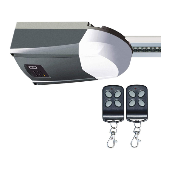
Summary of Contents for Schellenberg Smart DRIVE 10 PREMIUM
- Page 1 Smart DRIVE 10, 14 PREMIUM...
- Page 3 Deutsch ..........................................English ..........................................Français ..........................................Polska ..........................................Italiano ..........................................
-
Page 4: Table Of Contents
Kopplung mit Smart Home-Zentrale SH1 ....................... Urheberrechtlich geschützt, 2017, Alfred Schellenberg GmbH – alle Rechte vorbehalten. Jede vom Urheberrechtsgesetz nicht zugelassene Verwertung, insbesondere Vervielfäl- tigung, Übersetzung, Verarbeitung bzw. Weitergabe von Inhalten in Datenbanken oder anderen elektronischen Medien und Systemen, ist verboten. -
Page 5: Sicherheit Und Hinweise
SICHERHEIT UND HINWEISE Sehr geehrte Kundin, sehr geehrter Kunde, lesen Sie die Anweisungen sorgfältig vor der Montage und dem Betrieb des Produktes durch. Die Installation sollte von einer geeigneten Fachkraft vorgenommen werden. Fehlerhafte Installation oder selbst durchgeführte Repa- raturen können im Betrieb zu Verletzungen, Tod sowie Sachschäden führen. Folgen Sie allen Hinweisen für Ihre eigene Sicherheit und heben Sie diese Montageanleitung auf. -
Page 6: Grundfunktionen
Die Programmierung des Garagentorantriebes erfolgt direkt am Gerät. Die Steuerung erfolgt über den mitgelieferten Handsender oder per Smartphone bzw. Tablet über die dazugehörige App. Zur Steuerung per App benötigen Sie die SCHELLENBERG Smart Home-Zentrale SH1 (nicht im Lieferumfang enthalten). Softstart, Softstopp – Der Torantrieb startet und stoppt sanft, fast geräuschlos Selbstlernende Krafteinstellung Überlastungsschutz –... -
Page 7: A Einbau
inbau Einbau Lesen sie die Anleitung sorgfältig. Lesen sie die Anleitung sorgfältig. Lesen sie die Anleitung sorgfältig. Das Garagentor muss für die Verwendung des Torantriebs geeignet sein. A EINBAU Das Garagentor muss für die Verwendung des Torantriebs geeignet sein. Das Garagentor muss für die Verwendung des Torantriebs geeignet sein. Das Tor muss leichtgängig sein und sich widerstandsfrei bewegen lassen. -
Page 8: B Montage Der 3-Teiligen Stahl-Schiene
B MONTAGE DER 3-TEILIGEN STAHL-SCHIENE ontage der 3-teiligen Stahl-Schiene Abb. 4 ntage der 3-teiligen Stahl-Schiene Mittlere Schiene ntage der 3-teiligen Stahl-Schiene Mittlere Schiene Endschiene Endschiene Mittlere Schiene Endschiene Erste Verbindungsschiene Erste Verbindungshülse Erste Verbindungshülse Fig. 4 Fig. 4 Erste Verbindungshülse Erste Schiene Abb. - Page 9 Abb. 7 Chain tension: The chain tension is measured by the length of the spring, our recommended spring length after tightened need to be 17.5-19.5mm (see the pictures as 1. Schieben Sie die Schiene zusammen (Abb. 4). follows). 2. Schieben Sie die zweite Verbindungsschiene über das Ende der mittleren Schiene (Abb. 5). 3.
-
Page 10: C Montage Des Antriebes
ontage des Antriebs C MONTAGE DES ANTRIEBES Abb. 9 Deckenbefestigungs- schiene Stahlbolzen U-Befestigungs- Deckenbefestigungs- ET hanging bracket U bracket winkel (A) beschlag Abb. 10 Fig. 9 Wandbefestigungsbeschlag Wandbefestigungsbeschla Torbeschlag Torbefestigung Tor-Arm... -
Page 11: D Hinweise Zur Installation
D HINWEISE ZUR INSTALLATION 1. Befestigen Sie den Wandbefestigungsbeschlag ca. 2 – 15 cm (je nach Platzverhältnissen) oberhalb der oberen Tormitte (Abb. 9). 2. Befestigen Sie die Schiene mit dem Stahlbolzen (Abb. 9). 3. Mit den U-Befestigungswinkeln (A) befestigen Sie den Torantrieb an der Schiene (Abb. 9). 4. -
Page 12: E Grundfunktionen, Einstellung Und Anwendung
E GRUNDFUNKTIONEN, EINSTELLUNG UND ANWENDUNG EINSTELLUNG DER ENDPOSITIONEN Automatische Krafteinstellung Drücken Sie die SET-Taste bis das Display „1“ anzeigt. Stellen Sie die obere Endposition des Tores ein, indem Sie die UP-Taste drücken. Ca. 10cm vor Erreichen der oberen Torposition die UP-Taste loslassen. Nun durch mehr- maliges kurzes Drücken der UP-Taste das Tor in die gewünschte obere Torposition bringen und den Vorgang durch Drücken der SET-Taste ab- schließen. - Page 13 OPTIONALE KRAFTEINSTELLUNG Die am Antrieb werkseitig eingestellten Kräfte (Wert 3) sind für einen reibungslosen Betrieb von dafür vorgesehenen Stan- dardtoren ausgelegt; die in der Werkeinstellung ausgeübten Kräfte sollten grundsätzlich ausreichen, um das zu bedienende Tor vollständig zu öffnen und zu schließen. In der Werkseinstellung hält der Antrieb die gesetzlichen bzw. in einschlägigen Normen (wie z.B.
-
Page 14: F Weitere Funktionen Und Anwendungen
EINSTELLUNG LICHTSCHRANKE Drücken Sie die DOWN-Taste, bis die LED „II“ anzeigt. Drücken Sie die UP-Taste, um die Lichtschrankenfunktion zu aktivieren. Die LED zeigt „H“. Zum Deaktivieren drücken Sie die DOWN-Taste. Die LED zeigt „II“. Zum Bestätigen drücken Sie die SET-Taste. Schließen Sie die Lichtschranke an, wie in Abb. -
Page 15: Zubehörartikel: Smart Home-Zentrale Sh1
ZUBEHÖRARTIKEL: SMART HOME-ZENTRALE SH1 Für eine Steuerung mit dem Smartphone per App empfehlen wir die Smart Home-Zentrale SH1. Diese steuert alle Schellenberg Funk-Produkte per App. Das vorliegende Produkt können Sie dann als smarte Einzellösung verwenden oder in automatisierte Aktionen einbinden. -
Page 16: Zubehörartikel: Smartphone Garagentoröffner
– + out – com + ZUBEHÖRARTIKEL: SMARTPHONE GARAGENTORÖFFNER Für eine Steuerung mit dem Smartphone per App empfehlen wir den Schellenberg Smartphone Garagentoröff ner. Mit diesem lässt sich das Garagentor einfach mit einem Smartphone betreiben. Artikelnummer: 60999 Weitere Informationen zum Produkt und zur App fi nden Sie auf www.schellenberg.de. -
Page 17: G Manuelle Entriegelung
G MANUELLE ENTRIEGELUNG Manuelle Entriegelung Wie in Fig. 13 beschrieben, können Sie den Laufwagen vom Torantrieb trennen. Ziehen Sie an dem Griff und Wie in Abb. 13 beschrieben, können Sie den Laufwagen vom Torantrieb trennen. Ziehen Sie an dem Griff und bewegen Sie das Tor manuell. -
Page 18: K Technische Daten
K TECHNISCHE DATEN Smart DRIVE 10 PREMIUM / Smart DRIVE 14 PREMIUM / Modell / Art. Nr. 60912 (DE), 60916 (INT) 60915 (DE), 60914 (INT) Power Input 220 – 240 V AC 50/60 Hz 220 – 240 V AC 50/60 Hz... -
Page 19: M Garantie
- Smart DRIVE 10 PREMIUM, 4 Jahre = 48 Monate Im Garantiefall werden wir nach unserer Wahl das Pro- ... -
Page 20: Neg-Konformitätserklärung
N EG-KONFORMITÄTSERKLÄRUNG... -
Page 21: O Kopplung Mit Smart Home-Zentrale Sh1
O KOPPLUING MIT SMART HOME SYSTEM SH1 Koppeln Sie das Produkt mit dem Schellenberg Smart Home System oder dem Smart Friends System und benutzen Sie alle Schellenberg Funk-Produkte bzw. „Ready für Smart Friends“-Produkte über eine App miteinander. SCHELLENBERG SMART HOME SYSTEM Art.Nr. - Page 22 Pairing with the Smart Friends Box ........................ Copyright protected, 2017 Alfred Schellenberg GmbH. All rights reserved. Any use, in particular reproduction, translation, processing or transmission of content into databa- ses or other electronic media and systems beyond the authorization provided by the copyright legislation is strictly prohibited.
-
Page 23: Safety And Notices
SAFETY AND NOTICES Dear customers, read the instructions carefully before installing and operating the product. The installation should be carried out by a qualified specialist. Faulty installation or repairs carried out yourself can lead to injuries, death or damage to property during the operation. -
Page 24: Basic Functions
BASIC FUNCTIONS Congratulations on purchasing this product. The garage door drive has been developed with state-of-the-art technical know- ledge, and manufactured using the most reliable and modern electrical / electronic components. The garage door drive is programmed directly on the device. The control is performed via the supplied hand-held trans- mitter, or with a smartphone or tablet via the App. -
Page 25: A Installation
inbau Einbau Lesen sie die Anleitung sorgfältig. Lesen sie die Anleitung sorgfältig. Lesen sie die Anleitung sorgfältig. Das Garagentor muss für die Verwendung des Torantriebs geeignet sein. A INSTALLATION Das Garagentor muss für die Verwendung des Torantriebs geeignet sein. Das Garagentor muss für die Verwendung des Torantriebs geeignet sein. Das Tor muss leichtgängig sein und sich widerstandsfrei bewegen lassen. -
Page 26: B Assembly Of The 3-Piece Steel Rail
B ASSEMBLY OF THE 3-PIECE STEEL RAIL ontage der 3-teiligen Stahl-Schiene Fig. 4 ntage der 3-teiligen Stahl-Schiene Middle rail Mittlere Schiene ntage der 3-teiligen Stahl-Schiene Mittlere Schiene End rail Endschiene Endschiene Mittlere Schiene Endschiene First connecting rail Erste Verbindungshülse Erste Verbindungshülse Fig. -
Page 27: Schieben Sie Die Zweite Hülse Über Das Ende Der Mittleren Schiene (Fig
Fig. 7 Chain tension: The chain tension is measured by the length of the spring, our recommended spring length after tightened need to be 17.5-19.5mm (see the pictures as 1. Slide the rail together (Fig. 4). follows). 2. Slide the second connecting rail over the end of the middle rail (Fig. 5). 3. -
Page 28: C Mounting Of The Drive
ontage des Antriebs C MOUNTING OF THE DRIVE Fig. 9 Ceiling mounting rail Deckenbefestigungs- schiene Steel pin Stahlbolzen U-mounting U-Befestigungs- Ceiling mounting Deckenbefestigungs- ET hanging bracket U bracket bracket (A) bracket winkel (A) beschlag Fig. 10 Fig. 9 Wall mounting bracket Wandbefestigungsbeschla Door fitting Door arm... -
Page 29: D Instructions For The Installation
D INSTRUCTIONS FOR THE INSTALLATION 1. Fasten the wall mounting fitting approx. 2 - 15 cm (depending on the space) above the upper door middle part (Fig. 9). 2. Fasten the rail with the steel pin (Fig. 9). 3. Use the U-mounting brackets (A) to fasten the door drive to the rail (Fig. 9). 4. -
Page 30: E Basic Functions, Setting And Application
E BASIC FUNCTIONS, SETTING AND APPLICATION SETTING OF THE END POSITION Automatic force setting Press the SET button until the display shows „1“. Set the upper end position of the door by pressing the UP button. Wait approx. 10cm before the upper door position is reached, release the UP button. - Page 31 OPTIONAL FORCE SETTING The factory-set forces (value 3) are designed to enable a smooth operation of standard doors (which are intended for use with this drive). The forces exerted in the factory setting should fundamentally be sufficient to completely open and close the door to be operated.
-
Page 32: F Other Features And Applications
SETTING THE LIGHT BARRIER Press the DOWN button until the LED shows “II”. Press the UP button to activate the light barrier function. The LED shows “H”. To deactivate, press the DOWN button. The LED shows „II“. To confirm, press the SET button. Connect the light barrier as described in Figure 12. -
Page 33: Accessories: Smart Friends Box
ACCESSORIES: SMART FRIENDS BOX For smartphone control via the App, we recommend the Smart Friends Box. This used to control all Schellenberg wireless products via App. You can then use this product as a smart standalone solution, or integrate it into automated actions. -
Page 34: Accessories: Smartphone Garage Door Opener
– com + ACCESSORIES: SMARTPHONE GARAGE DOOR OPENER For smartphone control via the App, we recommend the Schellenberg Smart Home garage door opener. With this, the gara- ge door can be easily operated with a smartphone. Item No.: 60999 Further information on the product and the App can be found at www.schellenberg.de. -
Page 35: G Manual Release
G MANUAL RELEASE Manuelle Entriegelung Wie in Fig. 13 beschrieben, können Sie den Laufwagen vom Torantrieb trennen. Ziehen Sie an dem Griff und As described in Fig. 13, you can separate the carriage from the door drive. Pull on the handle and move the door manually. The door drive automatically reconnects with the door when you start it. -
Page 36: K Technical Data
K TECHNICAL DATA Smart DRIVE 10 PREMIUM / Smart DRIVE 14 PREMIUM / Model / type 60912 (DE), 60916 (INT) 60915 (DE), 60914 (INT) Power Input 220 – 240 V AC 50/60 Hz 220 – 240 V AC 50/60 Hz... -
Page 37: M Warranty
Schellenberg must be sent in as proof of purchase. ce on the part of the manufacturer. No claims going beyond Schellenberg is not liable under this warranty for collateral this on the basis of warranty obligations will be entertained. -
Page 38: N Pairing With The Smart Friends Box
N PAIRING WITH THE SMART FRIENDS BOX Pair the product with the Smart Friends System, and control all „Ready for Smart Friends“ products through the Friends app. www.smart-friends.com... - Page 39 Couplage avec la boîte Smart Friends ......................Soumis au droit d‘auteur, 2017, Alfred Schellenberg GmbH - Tous droits réservés. Interdiction de toute utilisation non autorisée par le droit d‘auteur, et notamment de la reproduc- tion, de la traduction, de la transformation ou de la transmission des contenus des bases de données ou des autres médias et systèmes électroniques.
-
Page 40: Sécurité Et Consignes
SÉCURITÉ ET CONSIGNES Chères clientes, chers clients, Lire les instructions soigneusement avant le montage et le fonctionnement du produit. L‘installation doit être effec- tuée par un professionnel adéquat. Une installation incorrecte ou des réparations effectuées soi-même peuvent entraîner des blessures, la mort et des dommages matériels lors du fonctionnement. Pour votre propre sécurité, suivre toutes les consignes et conserver ces instructions de montage. -
Page 41: Fonctions De Base
FONCTIONS DE BASE Félicitations pour l‘achat de ce produit. Le moteur de porte de garage est développé sur les nouvelles connaissances techni- ques en utilisant des éléments électriques, réliables et les plus modernes. La programmation du moteur de porte de garage s‘éffectue directement sur l‘appareil. Le contrôle s‘opère sur la télécom- mande inclue dans la livraison ou par smartphone respectivement tablet sur l‘application correspondante. -
Page 42: A Montage
inbau Einbau Lesen sie die Anleitung sorgfältig. Lesen sie die Anleitung sorgfältig. Lesen sie die Anleitung sorgfältig. Das Garagentor muss für die Verwendung des Torantriebs geeignet sein. A MONTAGE Das Garagentor muss für die Verwendung des Torantriebs geeignet sein. Das Garagentor muss für die Verwendung des Torantriebs geeignet sein. Das Tor muss leichtgängig sein und sich widerstandsfrei bewegen lassen. -
Page 43: B Montage Du Rail En Acier En 3 Pièces
B MONTAGE DU RAIL EN ACIER EN 3 PIÈCES ontage der 3-teiligen Stahl-Schiene Fig. 4 ntage der 3-teiligen Stahl-Schiene Rail central Mittlere Schiene ntage der 3-teiligen Stahl-Schiene Mittlere Schiene Rail final Endschiene Endschiene Mittlere Schiene Endschiene Premier rail de liaison Erste Verbindungshülse Erste Verbindungshülse Fig. - Page 44 Fig. 7 Chain tension: The chain tension is measured by the length of the spring, our recommended spring length after tightened need to be 17.5-19.5mm (see the pictures as follows). 1. Assembler le rail (fig. 4). 2. Glisser le deuxième rail de liaison au-dessus de l‘extrémité du rail central (fig. 5). 3.
-
Page 45: C Montage De La Motorisation
ontage des Antriebs C MONTAGE DE LA MOTORISATION Fig. 9 Rail de fixation au Deckenbefestigungs- plafond schiene Boulon en acier Stahlbolzen Équerre de fixation U-Befestigungs- Ferrure de fixation Deckenbefestigungs- ET hanging bracket U bracket en U (A) au plafond winkel (A) beschlag ... -
Page 46: D Consignes D'installation
D CONSIGNES D‘INSTALLATION 1. Fixer la ferrure de fixation murale à env. 2 – 15 cm (selon l‘espace disponible) au-dessus du centre supérieure de la porte (fig. 9). 2. Fixer le rail avec le boulon en acier (fig. 9). 3. Avec les équerres de fixation en U (A), fixer la motorisation de porte sur le rail (fig. 9). 4. -
Page 47: E Fonctions De Base, Réglage Et Utilisation
E FONCTIONS DE BASE, RÉGLAGE ET UTILISATION RÉGLAGE DES POSITIONS D‘EXTRÉMITÉ Réglage automatique de la force Appuyez sur la touche SET jusqu‘à ce que l‘écran affiche « 1 ». Réglez la position d‘extrémité supérieure de la porte en appuyant sur la touche UP. 10 cm env. - Page 48 RÉGLAGE DE LA FORCE OPTIONNEL Les forces réglées à l‘usine (valeur 3) sont dimensionnées pour un fonctionnement sans problème des portes standard prévus avec cette motorisation ; les forces exercées avec le réglage usine doivent par principe suffire pour ouvrir et fermer la porte à...
-
Page 49: F Autres Fonctions Et Utilisations
RÉGLAGE DE LA BARRIÈRE LUMINEUSE Appuyer sur la touche DOWN jusqu‘à ce que la DEL affiche « II ». Appuyer sur la touche UP afin d‘activer la fonction de la barrière lumineuse. La DEL affiche « H ». Pour désactiver, appuyer sur la touche DOWN. La DEL affiche «... -
Page 50: Accessoires : Boîte Smart Friends
Pour une commande avec le Smartphone via l‘application, nous recommandons la boîte Smart Friends. Cette dernière commande tous les produits radio Schellenberg via l‘application. Vous pouvez utiliser le produit existant comme solution individuelle intelligente ou l‘intégrer dans des actions automatisées. -
Page 51: Accessoires : Télécommande De Porte De Garage Sur Smartphone
ACCESSOIRES : TÉLÉCOMMANDE DE PORTE DE GARAGE SUR SMARTPHONE Pour une commande avec le Smartphone via une application, nous recommandons la télécommande de porte de garage sur Smartphone Schellenberg. Cette dernière permet de faire fonctionner la porte de garage avec le smartphone. Numéro d‘article : 60999 Vous trouverez des informations supplémentai-... -
Page 52: G Déverrouillage D'urgence
G DÉVERROUILLAGE D‘URGENCE Manuelle Entriegelung Comme décrit dans la fig. 13, vous pouvez séparer le chariot de la motorisation de porte. Tirer sur la poignée et déplacer Wie in Fig. 13 beschrieben, können Sie den Laufwagen vom Torantrieb trennen. Ziehen Sie an dem Griff und manuellement la porte. -
Page 53: K Caractéristiques Techniques
K CARACTÉRISTIQUES TECHNIQUES Smart DRIVE 10 PREMIUM / Smart DRIVE 14 PREMIUM / Modèle / Type 60912 (DE), 60916 (INT) 60915 (DE), 60914 (INT) Power Input 220 – 240 V CA 50/60 Hz 220 – 240 V CA 50/60 Hz Puissance absorbée... -
Page 54: M Durée De Garantie
Le délai de garantie est le suivant pour le moteur de com- mande : Merci d‘avoir opté pour un produit de la maison - Smart DRIVE 10 PREMIUM, 4 ans = 48 mois Schellenberg. Tous nos produits sont vérifiés soigneuse- - Smart DRIVE 14 PREMIUM, 6 ans = 72 mois ment et sont soumis aux contrôles de la garantie qualité... -
Page 55: N Couplage Avec La Boîte Smart Friends
N COUPLAGE AVEC LA BOȊTE SMART FRIENDS Coupler le produit avec le système Smart Friends et gérer tous les produits « Ready for Smart Friends » à l‘aide de l‘application Friends. www.smart-friends.com... - Page 56 Sprzężenie z Smart Friends Box ........................Urheberrechtlich geschützt, 2016, Alfred Schellenberg GmbH – alle Rechte vorbehalten. Jede vom Urheberrechtsgesetz nicht zugelassene Verwertung, insbesondere Vervielfäl- tigung, Übersetzung, Verarbeitung bzw. Weitergabe von Inhalten in Datenbanken oder anderen elektronischen Medien und Systemen, ist verboten.
-
Page 57: Bezpieczeństwo I Wskazówki
BEZPIECZEŃSTWO I WSKAZÓWKI Szanowna Klientko, Szanowny Kliencie przed przystąpieniem do montażu i użytkowania produktu należy dokładnie przeczytać niniejszą instrukcję. Instalacja powinna być wykonana przez właściwego specjalistę. Nieprawidłowa instalacja lub samodzielne wyko- nywanie napraw może powodować obrażenia, śmierć i szkody materialne. Dla własnego bezpieczeństwa należy postępować... -
Page 58: Podstawowe Funkcje
PODSTAWOWE FUNKCJE Gratulujemy zakupu tego produktu. Napęd bramy garażowej został opracowany zgodnie z aktualnym stanem wiedzy tech- nicznej i przy zastosowaniu najbardziej niezawodnych oraz nowoczesnych części elektrycznych i elektronicznych. Napęd bramy garażowej programuje się bezpośrednio na urządzeniu. Sterowanie odbywa się za pomocą znajdującego się w zestawie ręcznego pilota lub smartfona bądź... -
Page 59: A Montaż
inbau Einbau Lesen sie die Anleitung sorgfältig. Lesen sie die Anleitung sorgfältig. Lesen sie die Anleitung sorgfältig. Das Garagentor muss für die Verwendung des Torantriebs geeignet sein. A MONTAŻ Das Garagentor muss für die Verwendung des Torantriebs geeignet sein. Das Garagentor muss für die Verwendung des Torantriebs geeignet sein. Das Tor muss leichtgängig sein und sich widerstandsfrei bewegen lassen. -
Page 60: B Montaż 3-Częściowej Szyny Stalowej
B MONTAŻ 3-CZĘŚCIOWEJ SZYNY STALOWEJ ontage der 3-teiligen Stahl-Schiene Rys. 4 ntage der 3-teiligen Stahl-Schiene Szyna środkowa Mittlere Schiene ntage der 3-teiligen Stahl-Schiene Mittlere Schiene Szyna końcowa Endschiene Endschiene Mittlere Schiene Endschiene Pierwsza szyna łącząca Erste Verbindungshülse Erste Verbindungshülse Fig. 4 Fig. - Page 61 Rys. 7 Chain tension: The chain tension is measured by the length of the spring, our recommended spring length after tightened need to be 17.5-19.5mm (see the pictures as 1. Zsunąć szynę (rys. 4). follows). 2. Wsunąć drugą szynę łączącą na końcówkę środkowej szyny (rys. 5). 3.
-
Page 62: C Montaż Napędu
ontage des Antriebs C MONTAŻ NAPĘDU Rys. 9 Szyna mocowania sufi- Deckenbefestigungs- towego schiene Trzpień stalowy Stahlbolzen Kątownik U-Befestigungs- Okucie mocowania Deckenbefestigungs- ET hanging bracket U bracket montażowy U (A) sufitowego winkel (A) beschlag Rys. 10 Fig. 9 Okucie do montażu ściennego Wandbefestigungsbeschla Okucie bramy Ramię... -
Page 63: D Wskazówki Dotyczące Instalacji
D WSKAZÓWKI DOTYCZĄCE INSTALACJI 1. Przymocować okucie do montażu ściennego ok. 2–15 cm (zależnie od dostępnego miejsca) nad górnym środkiem bramy (rys. 9). 2. Przymocować szynę trzpieniem stalowym (rys. 9). 3. Przy użyciu kątowników montażowych U (A) przymocować napęd bramy do szyny (rys. 9). 4. -
Page 64: E Podstawowe Funkcje, Ustawianie I Użytkowanie
E PODSTAWOWE FUNKCJE, USTAWIANIE I UŻYTKOWANIE USTAWIANIE POŁOŻEŃ KRAŃCOWYCH Automatyczne ustawianie siły Nacisnąć przycisk SET i przytrzymać, aż na wyświetlaczu pojawi się „1”. Us- tawić górne położenie krańcowe bramy, naciskając przycisk UP. Ok. 10 cm przed osiągnięciem górnego położenia bramy zwolnić przycisk UP. Nacis- kając kilkakrotnie na krótko przycisk UP, ustawić... - Page 65 OPCJONALNE USTAWIANIE SIŁY Siły ustawione fabrycznie (wartość 3) zapewniają bezzakłóceniową pracę standardowych bram (przewidzianych do obsługi przy użyciu tego napędu). Siły wywierane przy ustawieniu fabrycznym powinny wystarczyć do całkowitego otwarcia i zam- knięcia obsługiwanej bramy. Przy ustawieniu fabrycznym napęd spełnia wymogi ustawowych lub odnośnych norm (np. EN 13241-1, EN 12453, EN 60335-2-95) względem sił...
-
Page 66: F Dalsze Funkcje I Zastosowania
USTAWIENIE ZAPORY ŚWIETLNEJ Nacisnąć przycisk DOWN i przytrzymać, aż na wyświetlaczu LED pojawi się „II”. Nacisnąć przycisk UP, aby włączyć funkcję zapory świetlnej. Na wyświetlaczu LED pojawi się „H”. Wcisnąć przycisk DOWN, aby wyłączyć. Na wyświetlaczu LED pojawi się „II”. W celu potwierdzenia nacisnąć przy- cisk SET. -
Page 67: Akcesoria: Smart Friends Box
AKCESORIA: SMART FRIENDS BOX Do sterowania za pomocą smartfona i aplikacji zalecamy Smart Friends Box. Umożliwia ona sterowanie wszystkimi produk- tami radiowymi firmy Schellenberg przy użyciu aplikacji. Niniejszy produkt może być używany jako pojedyncze rozwiązanie lub zintegrowany z czynnościami automatycznymi. -
Page 68: Akcesoria: Aplikacja Do Smartfona Do Otwierania Bramy Garażowej
Do sterowania za pomocą smartfona i aplikacji zalecamy aplikację na smartfona do otwierania bramy garażowej Schellen- berg. Umożliwia ona łatwe obsługiwanie bramy garażowego przy użyciu smartfona. Numer katalogowy: 60999 Więcej informacji na temat produktu i aplikacji jest dostępnych na stronie www.schellenberg.de. PODŁĄCZANIE APLIKACJI NA SMARTFONA DO OTWIERANIA BRAMY GARAŻOWEJ żółty zielony +24 V biały... -
Page 69: G Ręczne Odblokowywanie
G RĘCZNE ODBLOKOWYWANIE Manuelle Entriegelung Wie in Fig. 13 beschrieben, können Sie den Laufwagen vom Torantrieb trennen. Ziehen Sie an dem Griff und Wózek można odłączyć od napędu bramy w sposób przedstawiony na rysunku 13. Pociągnąć za uchwyt i przesunąć bramę ręcznie. -
Page 70: K Dane Techniczne
K DANE TECHNICZNE Smart DRIVE 10 PREMIUM / Smart DRIVE 14 PREMIUM / Model / nr kat. 60912 (DE), 60916 (INT) 60915 (DE), 60914 (INT) Wejście zasilania 220 – 240 V AC 50/60 Hz 220 – 240 V AC 50/60 Hz Moc użyteczna... -
Page 71: M Gwarancja
Okres gwarancji na silnik napędowy wynosi dziękujemy, że zdecydowali się Państwo na zakup produktu - Smart DRIVE 10 PREMIUM, 4 lata = 48 miesięcy - Smart DRIVE 14 PREMIUM, 6 lat = 72 miesiące firmy Schellenberg. Wszystkie nasze produkty są starannie sprawdzane i kontrolowane przez dział... -
Page 72: N Sprzężenie Z Smart Friends Box
N SPRZĘŻENIE Z SMART FRIENDS BOX Produkt można skojarzyć z systemem Smart Friends i sterować wszystkimi produktami „Ready for Smart Friends” razem przez aplikację Friends. www.smart-friends.com... - Page 73 Accoppiamento con Smart Friends Box ......................Protetto da copyright, 2017, Alfred Schellenberg GmbH - tutti i diritti riservati. È vietato qualsiasi tipo di utilizzo diverso da quello previsto dai diritti d’autore, in particolare la copia, la traduzione, l’elaborazione o la trasmissione dei contenuti in database o altri strumenti elettronici e sistemi.
-
Page 74: Sicurezza Ed Avvertenze
SICUREZZA ED AVVERTENZE Gentile cliente, prima delle operazioni di montaggio e l’uso del prodotto, si prega di leggere le istruzioni. L’installazione deve essere eseguita da personale specializzato adatto. Una installazione errata o riparazioni eseguite personalmente, durante il funzionamento possono provocare lesioni, la morte e danni materiali. Per la propria sicurezza si prega di rispetta- re tutte le avvertenze e conservare le presenti Istruzioni di montaggio. -
Page 75: Funzioni Di Base
Al termine delle operazioni di installazione, accertarsi che le parti del portone in funzione non sporgano su percorsi pedonali o strade pubbliche. FUNZIONI DI BASE Congratulazioni per l‘acquisto di questo prodotto. La motorizzazione è progettato sulla tecnologia più recente e realizzato con i componenti elettrici / elettronici più... -
Page 76: A Installazione
inbau Einbau Lesen sie die Anleitung sorgfältig. Lesen sie die Anleitung sorgfältig. Lesen sie die Anleitung sorgfältig. Das Garagentor muss für die Verwendung des Torantriebs geeignet sein. A INSTALLAZIONE Das Garagentor muss für die Verwendung des Torantriebs geeignet sein. Das Garagentor muss für die Verwendung des Torantriebs geeignet sein. Das Tor muss leichtgängig sein und sich widerstandsfrei bewegen lassen. -
Page 77: B Montaggio Del Binario Di Acciaio In 3 Parti
B MONTAGGIO DEL BINARIO DI ACCIAIO IN 3 PARTI ontage der 3-teiligen Stahl-Schiene Fig. 4 ntage der 3-teiligen Stahl-Schiene Binario centrale Mittlere Schiene ntage der 3-teiligen Stahl-Schiene Mittlere Schiene Endschiene Binario terminale Endschiene Mittlere Schiene Endschiene Primo binario di collegamento Erste Verbindungsschiene Erste Verbindungshülse Erste Verbindungshülse... - Page 78 Fig. 7 Chain tension: The chain tension is measured by the length of the spring, our recommended spring length after tightened need to be 17.5-19.5mm (see the pictures as follows). 1. Collegare il binario (Fig. 4). 2. Spingere il secondo binario di collegamento sull’estremità del binario terminale (Fig. 5). 3.
-
Page 79: C Montaggio Dell'automatismo
ontage des Antriebs C MONTAGGIO DELL’AUTOMATISMO Fig. 9 Binario di fissaggio a Deckenbefestigungs- soffitto schiene Perno di acciaio Stahlbolzen Angolare di fissaggio U-Befestigungs- Ferramento di fissaggio Deckenbefestigungs- ET hanging bracket U bracket ad U (A) a soffitto winkel (A) beschlag ... -
Page 80: D Avvertenze Sull'installazione
D AVVERTENZE SULL’INSTALLAZIONE 1. Fissare il ferramento di fissaggio a parete ca. 2 – 15 cm (in base allo spazio disponibile) sopra il centro superiore del portone (Fig. 9). 2. Fissare il binario con il perno di acciaio (Fig. 9). 3. -
Page 81: E Funzioni Di Base, Regolazione Ed Uso
E FUNZIONI DI BASE, REGOLAZIONE ED USO REGOLAZIONE DELLE POSIZIONI FINALI Regolazione automatica della forza Premere il tasto SET fino a quando sul display viene visualizzato „1“. Impost- are la posizione terminale superiore del portone premendo il tasto UP. Ca. 10cm prima di raggiungere la posizione superiore del portone, rilasciare il tasto UP. - Page 82 Grundfunktionen, Einstellung und Anwendung Einstellung der Endpositionen Automatische Krafteistellung Drücken Sie die SET-Taste bis das Display "1" anzeigt. REGOLAZIONE OPZIONALE DELLA FORZA Stellen Sie die obere Endposition des Tores ein, indem Sie die UP-Taste drücken. Wenn Sie die obere Le forze impostate di serie (Valore 3) sono previste per un funzionamento corretto con questo automatismo per portoni stan- Torposition gefunden haben, drücken Sie die SET-Taste.
-
Page 83: F Ulteriori Funzioni Ed Applicazioni
IMPOSTAZIONE DELLA BARRIERA LUMINOSA Premere il tasto DOWN fino a quando il LED segnala „II“. Premere il tasto UP per attivare la funzione della barriera luminosa. Il LED segnala „H“. Per la disattivazione, premere il tasto DOWN. Il LED segnala „II“.Per confermare premere il tasto SET. -
Page 84: Accessori: Smart Friends Box
ACCESSORI: : SMART FRIENDS BOX Per il controllo con lo smartphone tramite un’applicazione, consigliamo la Smart Friends Box. Questa controlla tutti i prodotti radio Schellenberg tramite lì’applicazione. Il presente prodotto può quindi essere usato come soluzione singola intelligente oppure includerlo in azioni automatizzate. -
Page 85: Accessori: Aprigarage Da Smartphone
– + out – com + ACCESSORI: APRIGARAGE DA SMARTPHONE Per il controllo con lo smartphone tramite un’applicazione, consigliamo l’aprigarage da Smartphone Schellenberg. Con esso è possibile gestire il portone del garage in modo semplice via smartphone. Codice prodotto: 60999 Ulteriori informazioni sul prodotto e l’applicazione sono disponibili all’indirizzo... -
Page 86: G Sblocco Manuale
G SBLOCCO MANUALE Manuelle Entriegelung Come descritto nella Fig. 13 è possibile scollegare il carrello di scorrimento dall’automatismo del portone. Tirare la manig- lia e spostare il portone manualmente. L’automatismo del portone si ricollega automaticamente con il portone quando lo si Wie in Fig. -
Page 87: K Dati Tecnici
K DATI TECNICI Smart DRIVE 10 PREMIUM / Smart DRIVE 14 PREMIUM / Modello / Tipo 60912 (DE), 60916 (INT) 60915 (DE), 60914 (INT) Power Input 220 – 240 V AC 50/60 Hz 220 – 240 V AC 50/60 Hz... -
Page 88: M Garanzia
M GARANZIA Gentile cliente, La garanzia del motore di trasmissione - Smart DRIVE 10 PREMIUM, 4 anni = 48 mesi La ringraziamo per aver deciso di acquistare un prodotto - Smart DRIVE 14 PREMIUM, 6 anni = 72 mesi della ditta Schellenberg. Tutti i nostri prodotti vengono a partire dalla data di acquisto da parte del primo cliente. -
Page 89: N Accoppiamento Con Smart Friends Box
N ACCOPPIAMENTO CON SMART FRIENDS BOX Coupler le produit avec le système Smart Friends et gérer tous les produits « Ready for Smart Friends » à l‘aide de l‘application Friends. www.smart-friends.com... - Page 92 Per la garanzia, pezzi di ricambio o informazioni sulle operazioni di montaggio corrette del prodotto, si prega di contattare il servizio di assistenza clienti. service.int@schellenberg.de Alfred Schellenberg GmbH An den Weiden 31 57078 Siegen service.int@schellenberg.de www.schellenberg.de...
Need help?
Do you have a question about the Smart DRIVE 10 PREMIUM and is the answer not in the manual?
Questions and answers