Table of Contents
Advertisement
Quick Links
Advertisement
Table of Contents

Subscribe to Our Youtube Channel
Related Manuals for Anthos A7 Plus


Summary of Contents for Anthos A7 Plus
- Page 1 97050644 Rev.006 2017.03...
-
Page 3: Table Of Contents
A7 Plus - OPERATING INSTRUCTION TABLE OF CONTENTS 5.5.3. IMPLANT operating mode ..........42 Safety guidelines ............4 5.5.4. Reduction ratio setting menu ......... 43 1.1. Symbol definition ............. 4 5.5.5. RECIPROCATING operating mode ....... 44 1.2. Intended use ..............4 5.6. Scaler ................45 1.2.1. Classification and reference standards ......4 5.7. -
Page 4: Safety Guidelines
Safety guidelines • These instructions explain how to correctly use the following dental units: A7 Plus CONTINENTAL, A7 Plus INTERNATIONAL Carefully read and become familiar with the content of this manual before using the equipment. • The dental units described in this manual are manufactured by CEFLA s.c. - via Selice Prov.le 23/A - 40026 Imola (BO) Italy, a manufacturer complying with the European Directive on devices. -
Page 5: Environmental Conditions
A7 Plus - OPERATING INSTRUCTION 1.2.2. Environmental conditions The equipment is to be installed in rooms that satisfy the following requirements: • temperature between 10 and 40°C. • relative humidity between 30 and 75%. • atmospheric pressure ranging from 700 to 1060 hPa. • altitude ≤ 3000 m; • air pressure entering equipment ranging from 6 to 8 bar. • water hardness entering equipment not over 60 mg/l. • water hardness at the equipment inlet must not be above 25 °f (French degrees) or 14 °d (German degrees) for untreated drinking water. For water with a higher hardness degree, it is recommended to soften water until it reaches a hardness degree between 15 and 25 °f (French degrees) or between 8.4 and 14 °d (German degreees); • water pressure entering equipment ranging from 3 to 5 bar. • water temperature entering equipment not higher than 25°C. 1.2.2.1. Transport and packaging conditions • Temperature: from -10 to 70°C; • Relative humidity: from 10% to 90%; • Atmospheric pressure: from 500 to 1060hPa. 1.2.3. Warranty CEFLA s.c. stands behind its products warranting safety, reliability and performance. The warranty is valid only under the following terms: • The conditions given on the warranty certificate are observed. -
Page 6: Safety Rules
A7 Plus - OPERATING INSTRUCTION 1.3. Safety rules WARNING! • All equipment is permanently installed. Depending on the type of chair the unit comes with, refer to the installation DATA given in paragraph “Specifications”. CEFLA s.c. shall not be held liable for any personal injury or equipment damage resulting from failure to heed the precaution given above. • Floor condition The floor conditions (continuous type) must meet design load standards set forth in DIN 1055 sheet 3. -
Page 7: Cleaning And Disinfecting
A7 Plus - OPERATING INSTRUCTION 1.4. Cleaning and disinfecting Cleaning is the first step of any disinfecting process. Physically scrubbing with detergents and surface-active substances and rinsing with water removes a considerable amount of micro organisms. If a surface is not clean first, the disinfecting process cannot be successful. If a surface cannot be adequately cleaned, it should be protected with barriers. The outer parts of the equipment must be cleaned and disinfected using a product for hospital use with indications for HIV, HBV and tubercolocide (medium-level disinfectant) specifically for small surfaces. The various drugs and chemical products used in dentist’s surgeries may damage the painted surfaces and the plastic parts. Research and tests run show that the surfaces cannot be fully protected against the harsh action of all products available on the market. We therefore recommend protecting with barriers whenever possible. The harsh actions of chemical products also depend on the amount of time they are left on the surfaces. It is therefore important not to leave the product on the surfaces longer than the time specified by the manufacturer. It is recommended to use the specific medium-level disinfectant, STER 1 PLUS (CEFLA s.c.), which is compatible with: • Coated surfaces and plastic parts. • Upholstery. WARNING! Any splashes or spots of mordant will stain the MEMORY FOAM upholstery. Immediately rinse with plenty of water if acid spatters on the upholstery. -
Page 8: Description Of The Equipment
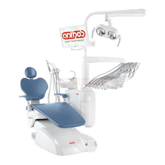
Data given on plate: • Manufacturer’s name • Name of equipment • Voltage • Type of current • Frequency • Maximum power absorbed • Serial number • Month and year of construction 2.2. Dental units Dental units A7 PLUS are available in the following versions: A7 PLUS CONTINENTAL version. “CONTINENTAL” version instrument board (instruments will return to their original position through the pulling action of the spring-operated arms) attached to a double supporting arm, one of which is articulated while the other is autobalancing. Description of equipment. Hydrogroup Adjustable arm Instrument board Doctor’s console Tray holder Assistant’s board Assistant’s control console... -
Page 9: Dental Chair
Maximum weight capacity. The maximum chair capacity is 190 Kg. WARNING! Do not exceed this value. Warnings for use. WARNING: FOOT CRUSHING HAZARD Pay attention to the patient and the staff during dental chair descent. Turning on the dental operatory Dental units model: A7 Plus CONTINENTAL, A7 Plus INTERNATIONAL. Press the main switch ( f1 ) on the dental chair casing and check on the control console that: • “POWER” led ( g ) on - equipment on - pneumatic system connected - water system connected. • “POWER” led ( g ) off... -
Page 10: Dental Chair Operation
The dental chair can be operated from the following places: • Instrument board ( a ) (see par. 5). • Multifunction foot control ( b ) (see par. 5.2). • Assistant’s board ( c ) (see par. 6). Dental chair movement shutdown With the instruments in rest position, you can disable the dental chair movements (see paragraph 5.1.1.2.5.). The movement disabling is shown on the control panel display by the relevant icon ( A ). 4.1. Safety devices A7 Plus series dental units. • The floor box is equipped with a device ( l ) that immediately stops the dental chair from moving down in the presence of an obstacle and auto- matically lifts it up to free the obstacle. • The chair back is equipped with a safety device ( m ) that immediately stops the chair back from moving down if an obstacle is encountered and automatically moves it up to clear the obstacle. • The support arms of the assistant’s module feature a safety device (n) which stops downward chair movement if an obstacle is encountered. The chair will then automatically move upwards so the user can remove the obstruction. • Dental chair movements: - with the instrument extracted NOT working: manual movements allowed, automatic movements inhibited, but if they are already in progress at the moment of extraction they are not interrupted;... -
Page 11: Adjustable Headrest
A7 Plus - OPERATING INSTRUCTION 4.3. Adjustable headrest The headrest may be of two types: with manual cushion lock lever with pneumatic cushion lock lever Adjusting headrest height. • with manual locking ( 1 ): The head rest blade is positioned through a magnetic clutch. The operator should pull up and/or push down the headrest until it is in the desired position. • with pneumatic locking ( 2 ): Press and hold down the locking button ( u ) to position the headrest as desired. Once you have reached the desired position, release the button ( u ) to lock the headrest in place. Adjusting the cushion: • with manual lock ( 1 ): rotate the lock knob ( k ) anti-clockwise, position the cushion as desired and then retighten the lock knob. • with pneumatic lock ( 2 ): press the lock button ( u ) and keep it pressed as you adjust the cushion as desired. Once the cushion is oriented as... -
Page 12: Instrument Board Operation
A7 Plus - OPERATING INSTRUCTION 5. Instrument board operation Layout of instruments. The positions the instruments are placed in on the board are determined by the customer at the time of order. Starting the instruments. • The syringe is always on (see paragraph 5.3.). • The curing light is turned on with the key when the instrument is withdrawn (see paragraph 5.7.). • Intraoral camera turn on when the instrument is extracted (see paragraph 5.8.). • The ZEN-Xi integrated sensor is started by turning its support to the “ACTIVE” position (see paragraph 5.9 and ZEN-Xi instructions for use). • Once picked up, all the instruments are operated with the foot control. (see paragraph 5.2.). Simultaneous use of the instruments. - Page 13 A7 Plus - OPERATING INSTRUCTION Cleaning the dentist’s instrument board. Clean the dentist’s instrument board using a suitable product (see para- graph 1.4). NOTE for CONTINENTAL version dentist’s instrument boards: the instrument holder ( x ) can be removed to facilitate the cleaning ope- rations; to remove it, simply pull it out of its seat as it is only secured with magnets.The silicone instrument holder ( u ) can also be sterilized in an...
-
Page 14: Doctor's Control Console
A7 Plus - OPERATING INSTRUCTION 5.1. Doctor’s control console The A7 PLUS series dental units have a SMART TOUCH “hybrid” denti- st’s console consisting of a membrane pushbutton panel and a resistive touchscreen display. 4.3” Wide colour TFT display with LED backlighting, resolution 480x272 pixels and 262k colours. Pushbutton panel for the following models: A7 Plus CONTINENTAL Pushbutton panel for the following models: A7 Plus INTERNATIONAL Description of the buttons: Dentist’s instrument board brake release button (INTERNATIONAL models) SMART TOUCH screen disable button Operatory light on/off button Water to cup button Auxiliary function button (available) Bowl counter-clockwise button ( active only with powered bowl). Bowl clockwise button ( active only with powered bowl) Water to bowl function button Dental chair functions save button Emergency position button. Automatic return button. Rinse position button. - Page 15 A7 Plus - OPERATING INSTRUCTION Warning icons. Touching the icon button on the touch display, you can at any time view the warning icons that show the operating status of the dental unit. The warning icons viewable are the following: WHE system running. Feeding with distilled water activated. Feeding with mains water activated. Peristaltic pump inserted with the delivered quantity of saline solution equal to 1. Distilled water level low. Low disinfectant liquid in the tank tubing. BIOSTER cycle in progress. Suction tubes being washed. Suction stopped due to full canister. Green: wireless foot control battery charged. Orange: wireless foot control battery 50% charged. Red: wireless foot control battery flat. Green: wireless foot control connected and active. Orange: wireless foot control connected but not active. Dental chair position automated programme D. Red: searching for connection to the wireless foot control. Dental chair movements blocked.
-
Page 16: User Interface
A7 Plus - OPERATING INSTRUCTION 5.1.1. User interface When turned on, the dental unit performs a brief autodiagnosis cycle that ends when the main screen containing the name of the operator last set is displayed. As of this moment a number of settings can be edited from user-friendly menus (see diagram). Menu scrolling control. • To access the setting menu, touch the icon button • To access the various submenus, touch the relative icon button. • To change a setting in a menu, touch the relative icon button. 5.1.1.1. 5.1.1.2. • To change a numerical value in a menu, touch the icon buttons or • To exit from a menu, touch the icon button 5.1.1.2.1. 5.1.1.2.1.1. Layout of the user interface menu. The user interface menu is structured as shown in the diagram and includes the following menus: 5.1.1.2.2.1. 5.1.1.2.2. 5.1.1.2.1.2. 5.1.1.1. Operator selection. -
Page 17: Operator Selection
A7 Plus - OPERATING INSTRUCTION 5.1.1.1. Operator selection The SMART TOUCH console of the A7 PLUS series dental units allows managing 3 different operators. The following data can be set for each operator: • Operator's name. • Turbine and scaler power adjustment. • 3 electric micromotor operating modes • 4 scaler operating modes . • Turning on and adjustment of the fibre optics of each instrument. • Incremental or ON/OFF control of the turbine and the scaler power . • Automatic dental chair movement programs. • Hydro unit configuration parameters Operator selection. From the main page, repeatedly touch the icon button until finding the desired operator. NOTE: the operator is changed cyclically. 5.1.1.2. General settings From the main page, carry out the following operations: • Touch the icon button... -
Page 18: Hygiene System Settings
A7 Plus - OPERATING INSTRUCTION 5.1.1.2.1. Hygiene system settings NOTE: menu available only if at least a hygiene system is present. From the GENERAL SETTINGS menu touch the icon button access the HYGIENE SYSTEM SETTINGS submenu containing the... -
Page 19: Flushing Cycle Setting
A7 Plus - OPERATING INSTRUCTION 5.1.1.2.1.2. Flushing CYCLE SETTING This setting is shared by all users. From the HYGIENE SYSTEM SETTINGS menu carry out the following operations: • Touch the icon button to access the FLUSHING CYCLE SETTING submenu . NOTE: this submenu cannot be entered if the distilled water tank is low (see paragraph 7.2.). A message on the control panel display and an acoustic signal (BEEP) will signal the impossibility to enter the submenu. -
Page 20: Hydro Unit Settings
A7 Plus - OPERATING INSTRUCTION 5.1.1.2.2. Hydro unit settings From the GENERAL SETTINGS menu touch the icon button to access the HYDRO UNIT SETTINGS submenu containing the following icon buttons: Water to bowl settings Water to cup settings Automatic bowl movement setting (only with motor-driven bowl) 5.1.1.2.2.1. Bowl water delivery setting From the HYDRO UNIT SETTINGS menu touch the icon button access the BOWL WATER SETTING submenu containing the following icon buttons: Bowl flushing controller with dental chair brought to rinse position Bowl flushing controller with dental chair brought to reset position Cuspidor bowl flushing automatism with return from the rinse position for the chair A Bowl flushing controller with cup call Setting of timed or ON/OFF bowl flushing Bowl flushing time (in seconds ) • To select/deselect a function, touch the relative icon button. -
Page 21: Cup Water Delivery Setting
A7 Plus - OPERATING INSTRUCTION 5.1.1.2.2.2. Cup water delivery setting From the HYDRO UNIT SETTINGS menu touch the icon button to access the CUP WATER SETTING submenu containing the following icon buttons: COLD cup water selection WARM cup water selection HOT cup water selection Cup water delivery time (in seconds ) Cup water delivery automatic function with rinse position recall. Cup detection sensor activation/deactivation Distilled water tank depressurization automatic function with chair home position recall • To select/deselect a function, touch the relative icon button. • To change the cup water delivery time, touch the icon buttons or NOTE: the cup time of filling can be set up from a minimum of 1 second to a maximum of 10 seconds with increments of 0.1 seconds. -
Page 22: Foot Control Adjustment
A7 Plus - OPERATING INSTRUCTION 5.1.1.2.3. Foot control adjustment From the GENERAL SETTINGS menu touch the icon button access the FOOT CONTROL ADJUSTMENT submenu containing the following icons: Cable connection icon (only with wireless foot control) Wireless connection status icon (only with wireless foot control) Battery percentage charge icon (only with wireless foot control) Foot control joystick with extracted instrument operation setting NOTE: the first 3 icons are just for signalling, while the fourth one al- lows to select/deselect the operation mode of the foot control upper joystick. -
Page 23: Other Settings
A7 Plus - OPERATING INSTRUCTION 5.1.1.2.5. Other Settings These settings are alike for all operators. From MAIN SETTINGS menu, touch icon button to access the OTHER SETTINGS sub-menu including the following icon buttons: Pantograph arm brake release activation/deactivation Touch display acoustic signal activation/deactivation Dental chair movement activation/deactivation Brake sensitivity adjustment Display brightness adjustment • To activate/deactivate pantograph arm brake release, touch the relative icon button. NOTE: when the brake cannot be released, it is indicated by a dedicated icon on the TOUCH DISPLAY (see paragraph 5.1.). -
Page 24: Chronometer
A7 Plus - OPERATING INSTRUCTION 5.1.1.2.7. Chronometer This setting is shared by all users. From the GENERAL SETTINGS menu touch the icon button to access the CHRONOMETER SUBMENU. • To change the various data displayed , touch the relative icon buttons NOTE: the time can bet set from 00:00:00 to 10:59:59. • Once you have set the time, touch the icon button to start the countdown. -
Page 25: Operator Data Entry
A7 Plus - OPERATING INSTRUCTION 5.1.1.2.9. Operator data entry From the GENERAL SETTINGS menu touch the icon button access the OPERATOR DATA ENTRY submenu. NOTE: the data modified always refers to the operator set on the main page. • To enter the desired text, touch the icon buttons of the various letters (max. 20 characters). • To enter capital letters, touch the icon button • To enter numbers or special characters, touch the icon button • To cancel any typing mistakes, touch the icon button cancelling from left to right. -
Page 26: Programming The Chair Positions A, B, C And D
A7 Plus - OPERATING INSTRUCTION 5.1.2. Dental chair "Rinsing position" and "Reset position" pro- gramming This setting is specific for each single operator. From main screen, carry out the following operations: • Adjust the dental chair into the desired position with the manual move- ment buttons. NOTE: when motorised, it is possible to also store the bowl position. • Hold button “SAVE” for at least 2 seconds to activate save mode. Save mode activation is signalled by a short acoustic signal (BEEP) and by the corresponding icon ( A ) on the TOUCH DISPLAY. NOTE: hold down button "SAVE" for at least 2 seconds to quit without >2 sec saving the changes made. • Press the AUTOMATIC RETURN or RINSE POSITION buttons to asso- ciate the position with the button. The appearance of icon ( B ) relating to the selected programme on the TOUCH DISPLAY will confirm that it has been saved. NOTE: in RINSE POSITION the seat height cannot be changed. NOTE: the RINSING POSITION button moves backrest and seat to rinsing position. When RINSING POSITION button is pressed again, backrest and seat will go back to the previous position. 5.1.3. Programming the chair positions A, B, C and D This setting is specific for each operator. -
Page 27: Foot Control
A7 Plus - OPERATING INSTRUCTION 5.2. Foot control 3 types of foot controls are available: "Multifunction” foot control "Push-pedal” foot control "Power Pedal" foot control. NOTE: the "multifunction" and "pressure" foot controls can also be supplied in wireless version. 5.2.1. "Multifunction” foot control Description of the parts Handle Control pedal Dental chair movements Chip-air/patient rinsing position control. Water Clean System/Automatic dental chair return control. LED (not active). Battery charge LED (wireless version only). Joystick for dental chair movement (3). -
Page 28: Push-Pedal" Foot Control
A7 Plus - OPERATING INSTRUCTION Left-hand button operation ( 4 ). • Key held down (at least 2 seconds) with the instrument removed: Chip-air operation: delivers air to the turbine or micromotor. Air is delivered by pressing the button. Air is no longer blown when the button is released. • Key held down (at least 2 seconds) with the instruments in place: "Rinse position” (PR) program activated. NOTE: Press the key again to bring the chair back to the work position. - Page 29 A7 Plus - OPERATING INSTRUCTION Joystick for dental chair movement (3). These buttons move the dental chair as follows: Dental chair seat up. Dental chair backrest up. Dental chair seat down. Dental chair backrest down. To stop the chair movement, release the joystick. NOTE: All the buttons used to move the dental chair are inoperative when an instrument is removed and the foot control pedal is actuated.
-
Page 30: Power Pedal" Foot Control
A7 Plus - OPERATING INSTRUCTION 5.2.3. "Power Pedal" foot control Description of the parts. 1 Handle. 2 Foot control. Dental chair movements. 4 Chip-air control or activation/deactivation of instrument spray function. 5 Water Clean System control or activation/deactivation of instrument spray function. 6 Automatic dental chair return or programme "B” recall activation. 7 Patient rinse position or programme "A" recall activation. 8 Spray operation LED. Foot control operation ( 2 ). • With instrument removed - Pushing the pedal ( a ), the instrument is started. - Page 31 A7 Plus - OPERATING INSTRUCTION Right lever operation ( 6 ). NOTE: the lever functions only with the instruments in their rest position. For safety reasons, the selected function starts only after the switch has been briefly actuated and then released. • Lever pushed down: "Dental chair automatic return” program activated. • Lever pulled up: Dental chair program “B" start. Left lever operation ( 7 ). NOTE: the lever functions only with the instruments in their rest position.
-
Page 32: Wireless Foot Control
A7 Plus - OPERATING INSTRUCTION 5.2.4. Wireless foot control The "multifunction" and "pressure" foot control can also be supplied in wireless version. The wireless foot control contains a ZIGBEE transmitter module (module certified for Europe, Canada and the USA). Warnings for use. WARNING! • Avoid keeping the wireless foot control in proximity of other RF sources, such as wireless LAN cards, other radio devices, home RF de- vices, microwave ovens. - Page 33 A7 Plus - OPERATING INSTRUCTION Recharging the battery. When the batteries in the WIRELESS foot control need to be recharged, operate as follows: • Open the protective cap of the connector on the rear of the foot control and connect the recharging cable. • Connect the other end of the recharging cable to the dental unit (see figure). At this point, the foot control, while it remains fully operational, will start recharging the battery ( Battery charging warning LED on ). NOTE: The battery is fully recharged in about 6 hours. WARNING! Exclusively use the dental unit to charge the battery of the WIRE- LESS foot control.
-
Page 34: Syringe
A7 Plus - OPERATING INSTRUCTION 5.3. Syringe Description of the instrument. [ a ] Nozzle. [ b ] Handpiece. [ c ] Syringe release button. [ d ] Air button. [ e ] Water button. [ f ] Hot/cold selector. [ g ] Hot/cold indicator light. WARNING! The instrument is supplied non-sterile. It is recommended to use single-use protections and nozzles. -
Page 35: Turbine
A7 Plus - OPERATING INSTRUCTION 5.4. Turbine Connecting the handpiece and changing the chuck. Refer to the specific instructions furnished with the handpiece. Use. WARNING! Read the instructions for use of the various turbines. • The cock ( f ) adjusts the water flow to the spray. • The cock ( e ) adjusts the amount of air spray for all the instruments. • Place the instrument in its work position. NOTE: instrument activation is indicated by the relative manage- ment page appearing on the TOUCH DISPLAY. - Page 36 A7 Plus - OPERATING INSTRUCTION Turbine rotation speed change. With the instrument in working position, select turbine speed change mode by touching the following icon buttons: Linear change proportional to the movement of the the foot control lever ON/OFF change that results in delivery of the maximum power set upon activation of the foot control lever The active mode icon is shown on the TOUCH DISPLAY. NOTE: the data is automatically stored. Instrument spray control button. With the instrument in working position, select the type of spray delivered by the instrument by touching the following icon buttons: Water + air spray operation Water-only spray operation Operation without spray The change is cyclic each time the button is touched and the active mode icon is shown on the TOUCH DISPLAY. NOTE: the data is automatically stored. Peristaltic pump activation/deactivation (only if present).
-
Page 37: Micromotor
A7 Plus - OPERATING INSTRUCTION 5.5. Micromotor Coupling the handpieces and changing the chuck. Refer to the specific instructions furnished with the micromotor and various handpieces. Use. WARNING! Also read the instructions for use of the various motors. The instrument is supplied non-sterile. • Operating time: work 5 min., rest 5 min. - Page 38 A7 Plus - OPERATING INSTRUCTION Instrument spray control button. With the instrument in working position, select the type of spray delivered by the instrument by touching the following icon buttons: Water + air spray operation Water-only spray operation Operation without spray The change is cyclic each time the button is touched and the active mode icon is shown on the TOUCH DISPLAY. NOTE: the data is automatically stored. Rotation speed change mode selection. With the instrument in working position, select rotation speed change mode by touching the following icon buttons: Linear change proportional to the movement of the the foot control lever ON/OFF change that results in delivery of the maximum power set upon activation of the foot control lever The active mode icon is shown on the TOUCH DISPLAY. NOTE: the data is automatically stored.
- Page 39 A7 Plus - OPERATING INSTRUCTION Reduction ratio selection. Using the icon buttons or you can select the desired reduction ratio from those stored. The torque value (set or current) is expressed in % or Ncm for the certified reduction gears. WARNING! An icon appears next to the torque value identifying the reading tolerance on the value indicated: tolerance of ±10% tolerance of ±20%. NOTE: the data is automatically stored.
-
Page 40: Restorative Operating Mode
A7 Plus - OPERATING INSTRUCTION Safety guidelines. WARNING! • Never put the contra angle on the micromotor while it is running. • The chuck release button must be held down during operation! Friction between the button and micromotor rotor overheats the head and may cause burns. - Page 41 A7 Plus - OPERATING INSTRUCTION Menu with micromotor extracted but not active. All the icon buttons are active and each function available can be changed (see paragraph 5.5.). As well as the standard settings, in ENDODONTIC mode you can also set “Operation when maximum torque reached” by touching the relative icon button: Rotation lock Rotation lock and subsequent inversion of the rotation direction Rotation lock, inversion of the normal rotation direction and subse- quent return to the normal rotation direction NOTE: each setting or value changed will automatically be stored in the operating program selected (e.g. P1). Below is the list of symbols relating to the types of certified counterangle shown on the TOUCH DISPLAY:...
-
Page 42: Implant Operating Mode
A7 Plus - OPERATING INSTRUCTION 5.5.3. IMPLANT operating mode Characteristics. - Speed adjustable from 5 to 2500 rpm with the value always referring to the drill irrespective of the reduction ratio (20:1 to 1000:1 reduction gears) - Torque adjustable from 0.5 to 55.0 Ncm for the certified reduction gears or from 1 to 100% - Customisable list of reduction ratios - Alarm signal when the maximum torque is reached - calibration button during motor rotation. Menu with micromotor extracted but not active. All the icon buttons are active and each function available can be changed (see paragraph 5.5.). NOTE: each setting or value changed will automatically be stored in the operating program selected (e.g. -
Page 43: Reduction Ratio Setting Menu
A7 Plus - OPERATING INSTRUCTION 5.5.4. Reduction ratio setting menu From the menu relating to the micromotor extracted but not active, touch the icon button to access the REDUCTION RATIO SETTING SUBMENU containing the following icon buttons: Selection of the reduction ratios stored Exit from the menu with storage of the ratio selected Creation of a customised reduction ratio Modification of a customised reduction ratio NOTE: the RPM icon is not a modifiable field, as it only displays the maximum speed reachable with the reduction ratio selected. -
Page 44: Reciprocating Operating Mode
A7 Plus - OPERATING INSTRUCTION 5.5.5. RECIPROCATING operating mode Characteristics. - 2 selectable reduction ratios: 4:1 and 6:1, - 3 selectable root canal drills, - progressive alarm signal starting from 60% of maximum set torque. Menu with micromotor extracted but not active. All icon buttons are active and all available functions can be edited (see paragraph 5.5.). In addition to the standard settings, the RECIPROCATING mode also allows adjusting the following functions: • Reversing micromotor drill rotation direction. Select micromotor drill rotation direction by touching the relevant icon button: Standard rotation direction: Rotation with reciprocating motion. -
Page 45: Scaler
A7 Plus - OPERATING INSTRUCTION 5.6. Scaler Connecting the handpiece and inserts. Refer to the specific instructions furnished with the handpiece. WARNING! Before attempting to connect the handpiece, make certain the contacts are perfectly dry. Blow air from the syringe, if necessary, to dry. Safety guidelines WARNING! • Make sure the threaded sections of the inserts and handpiece are perfectly clean. - Page 46 A7 Plus - OPERATING INSTRUCTION Scaler power change mode selection. With the instrument in working position, select scaler power change mode by touching the following icon buttons: Linear change proportional to the movement of the foot control lever ON/OFF change that results in delivery of the maximum power set upon activation of the foot control lever The active mode icon is shown on the TOUCH DISPLAY. NOTE: the data is automatically stored. Cooling water enable. With the instrument in working position, select whether or not water should be delivered by the instrument by touching the following icon buttons: Operation with water Operation without water The change is cyclic each time the button is touched and the active mode icon is shown on the TOUCH DISPLAY. NOTE: during operation without water, the maximum power delivered is 50% of the maximum power settable.
- Page 47 A7 Plus - OPERATING INSTRUCTION Removable cord The scaler has a removable cord to ease cleaning (see paragraph 5.). Cleaning and care. Refer to the specific instructions furnished with the instrument. WARNING! • Do not soak the handpiece in liquid disinfectants or detergents. Sterilization. • Torque wrench, scaler bits and scaler handpiece: steam autoclave up to 135°C following the instructions for use of the device. WARNING! Carefully read the operating instructions supplied with the instrument before attempting to sterilize.
-
Page 48: T Led Curing Light
A7 Plus - OPERATING INSTRUCTION 5.7. T LED curing light Technical specifications. Supply voltage: 24-36 VDC Max. power absorbed: 6 VA Light source: 1 5W LED Wavelength: 430-490 nm Acoustic signals: at cycle start, every 5 seconds, and at cycle end Type of operation : intermittent (3 consecutive cycles - 60 sec. rest) Programs: 6 (preset) General description of the light a) Light handpiece b) Rotary end section c) Fiber optic d) Eye protection e) Power cord Start button NOTE: The curing light can be used in different configurations (wand, gun or any intermediate position) to aid the user. - Page 49 A7 Plus - OPERATING INSTRUCTION • Take the light out of its housing on the assistant’s board or instrument board. NOTE: instrument activation is indicated by the relative management page appearing on the TOUCH DISPLAY. • Turn the front of the light and/or fiber optic to the position most suitable for curing (wand, gun or intermediate position). • Use the MODE button to select the desired cycle as previously directed (the selected cycle is always indicated by the illuminated LED). NOTE: The curing light has a permanent memory therefore the last cycle used will always be present the next time it is used.
- Page 50 A7 Plus - OPERATING INSTRUCTION Safety guidelines. WARNING! • The LED is a Class 2 light source in accordance with IEC 62471. DO NOT FIX THE BEAM. The light emitted may cause eye damage in the event of direct radiation without eye protection. Eye protection must always be worn when using the curing lamp and do not direct the light beam in eyes. The light emitted may damage soft tissues (oral cavity mucous, gums, skin). Be extremely careful to direct the light precisely on the material to be cured.
-
Page 51: C-U2 Dental Camera
A7 Plus - OPERATING INSTRUCTION 5.8. C-U2 dental camera The C-U2 dental camera system, complete with an extremely lightweight ergonomic handpiece, is specially designed for simple and well-conceived usability in examining the oral cavity. Auto-exposure and fixed focus features provide easy operation. This system is designed to allow the dentist to more efficiently show and explain to patients all oral conditions and reasons for planned treatment. The C-U2 system allows filming and taking high-definition (1280x720) live images of the section in question to be taken through a touch of a fingertip on the touch-sensitive area of the handpiece. The live intraoral images are displayed on the monitor or Personal Computer. WARNING! The camera may be used as a diagnostic tool however the results are to be compared to direct observation and/or other diagnostic means. Dia- gnosis based solely on the image obtained by the camera may result in poor evaluation as the electronically processed colors and shapes, may not correspond to those truly present. - Page 52 A7 Plus - OPERATING INSTRUCTION • Briefly press the foot control to stop from 1 to 16 images divided in 4 pages on the monitor. NOTE: The images shown on the monitor by the camera are only temporarily saved. To permanently save the images, connect the camera to a PC that complies to standard IEC 60950 which has a USB 2.0 HIGH SPEED port and image software program.
- Page 53 A7 Plus - OPERATING INSTRUCTION Operation in single image mode. Take out the camera in LIVE mode and set to single image mode, the “live” image appears on the monitor: • Tap the touch button [ g ] on the camera’s handpiece (or actuate the foot control) to freeze the image which is immediately displayed on the monitor, deleting any previous images. • Touching the icon button the last frozen image is displayed. NOTE: The last image frozen remains on the monitor even if the camera is put back in place. Operation in multiple image mode Extracting the camera in LIVE mode and in multiple image mode, a “moving”...
- Page 54 A7 Plus - OPERATING INSTRUCTION Handpiece status. An optical guide, illuminated by a multicolour LED indicator, found in the area near the control button (h), shows handpiece status as per the table given below: Color Situation Blue light flashes, very slowly Handpiece in standby Handpiece activated, live images Light blue steady light displayed Blue/ light blue flashing light Handpiece in image freeze mode Internal error: contact Customer Ser- Brief red flashes vice MyRay iCapture This program allows the C-U2 camera to be set up when it is connected to a PC/WORKSTATION. For a full description on how the MyRay iCapture program works, refer to the instructions, in electronic format, supplied with the C-U2 handpiece. Disposable infection control sheaths The camera can be a source of cross-contamination between patients.
-
Page 55: Zen-Xi Integrated Sensor
A7 Plus - OPERATING INSTRUCTION 5.9. ZEN-Xi integrated sensor Integrated sensor ZEN-Xi is a medical device employed to acquire intraoral x-rays in an electronic format with a Personal Computer interface device. When used together with dental practice management software, the x-ray pictures can be saved in the patient's folder and viewed on the desktop pc monitor at a later time. WARNING! Do not use the system for any other purpose different from acquisition of intraoral x-rays and do not use it if you are not a professional in the dental and radiology fields. Use. Use and care instructions for integrated sensor ZEN-Xi are enclosed with the apparatus. NOTE: Integrated sensor ZEN-Xi does not interact with the dental unit... -
Page 56: Peristaltic Pump
A7 Plus - OPERATING INSTRUCTION 5.10. Peristaltic pump This device allows saline solution to be supplied through a single-use administration line without any contact. Devices available only with the micromotor. NOTE: for the use of the micromotor, it is necessary to have recourse to contra angles with external cooling or for R20-L type (hollow drills ). -
Page 57: Electronic Apex Locator
A7 Plus - OPERATING INSTRUCTION 5.11. Electronic APEX LOCATOR APEX LOCATOR, through the analysis of the variations of special electric signals, makes root apex location easier. If used together with a "file" (not supplied) for manual treatment, it proves useful also to measure canal length. Besides using the apex locator in manual mode on this dental unit, this device can also be used with micromotor "ENDO" mode. The position of the instruments used on handpieces can be monitored since, through instrument cords, APEX LOCATOR signals are directly transferred to the files, thus allowing to monitor canal position during treatments. Component description. [ 1 ] APEX LOCATOR external wiring. - Page 58 A7 Plus - OPERATING INSTRUCTION Root canal length detection. • The use of manual file is of the utmost importance for canal detection. The correct procedure entails file insertion inside canal until reaching indi- cation 0.5. • Continue inserting file with a slow clockwise rotation until the APEX indication appears on the instrument. • Once APEX indication appears, stop file turning it counter clockwise until reaching again the value of 0.5. Position a rubber stopper close to the occlusal surface as a reference point to define the work length inside root canal. • Make an X-ray to check file correct positioning. • Remove file from canal and measure the work length with a ruler. Deduct a safety value of 0.5-1 mm from the reading. WARNING! Use APEX LOCATOR always in combination with X-ray test to accurately define apex position. Different, and not always predictable, morphological conditions could lead to inaccurate readings. For example: - excessively wide root canal; - re-treatments; - broken roots; - presence of metal crowns.
-
Page 59: Assistant's Board Operation
A7 Plus - OPERATING INSTRUCTION 6. Assistant’s board operation Main features. • Two articulated arms secure the board ( a ) to the hydrogroup ( b ) allowing it to be placed in the most convenient work position. The fixed arm ( c ) can turn 120° around the bowl. The pantograph arm ( e ) allows the assistant’s board to be moved 335 mm vertically through 6 work positions. NOTE: To completely lower the assistant’s board, simply move it all the way up and then lower it. • The assistant’s board ( a ) comes with a control console ( d ) with buttons used to operate the dental chair and hydrogroup. -
Page 60: Syringe On Assistant's Board
A7 Plus - OPERATING INSTRUCTION 6.2. Syringe on assistant’s board For detailed information regarding operation of this instrument see para- graph 5.3. 6.3. Curing lamp on assistant’s board For detailed information regarding operation of this instrument see para- graph 5.7. 6.4. Intraoral camera on assistant’s board For detailed information regarding operation of this instrument see para- graph 5.8. -
Page 61: Suction Tubes
A7 Plus - OPERATING INSTRUCTION 6.5. Suction tubes Suction starts by taking the tube off the board. To adjust suction, use the slider ( a ) located on the tube handpiece. NOTE: When the tube is put back in place, suction stops approxi- mately 2 seconds later. This is done to dry the suction tubes. Cleaning the suction tubes. As the dental units may be equipped with different suction systems (liquid... -
Page 62: Instrument Tray
A7 Plus - OPERATING INSTRUCTION 6.6. Instrument tray. The instrument tray ( a ) is constructed in stainless steel and can be con- veniently taken off its support. The tray holder can be turned either clockwise or counter-clockwise, allowing it to be placed in the most convenient position for the operator. To lock/unlock the tray holder, simply using the clutch knob ( b ). WARNING! Maximum allowable load that can be applied on instrument tray: 1 Kg evenly distributed. 6.7. Hydraulic saliva... -
Page 63: Hydrogroup Operation
A7 Plus - OPERATING INSTRUCTION 7. Hydrogroup operation 7.1. Fill cup and bowl The bowl can freely move 305° on the hydrogroup. The bowl may be po- wered (optional) or can be turned by hand. The bowl and water to cup spout can be removed to ease cleaning. Control buttons. Water to cup button. Bowl flush button. Cup sensor. You can have an optical sensor fitted at the base of the cup fountain, which detects the cup and automatically activates filling. The sensor operates as follows: • 2 seconds after positioning the cup under the fountain, it is filled with water for 2 seconds (this time is not modifiable) • Once the cup has been removed, the filling cycle can be repeated only after 3 seconds • During the filling cycle, removing the cup and/or pressing the “CUP... - Page 64 A7 Plus - OPERATING INSTRUCTION Taking off the bowl filter and rinse spout. • Pull up the spout ( l ) and take it off. • Pull up the filter ( q ) and its cover ( p ) to remove them. • Turn the bowl ( m ) counter-clockwise to release it and then pull it up to take it out. Disinfecting and cleaning. WARNING! Always wear gloves to prevent contact with infected material when cleaning the bowl and bowl filter. The parts are to be cleaned daily at the end of each work day. • Spouts and bowl: thoroughly wash with a specially formulated cleaner (for example MD 550 Orotol DÜRR). • Bowl filter: clean with running water and commercially-available cleaning products. WARNING! Do not use acids or harsh products.
-
Page 65: System
A7 Plus - OPERATING INSTRUCTION 7.2 S.H.S. system Description of the system The S.H.S. system is equipped with a distilled water tank ( a ). The tank can hold 1.8 liters. Distilled water is delivered to: • the sprays of all the instruments found on the instrument and assistant’s board. • The syringe on the assistant’s board. • to fill the cup • water quick-connect coupler (if present) The icon button on the TOUCH DISPLAY (see paragraph 5.1.1.2.8.) or the button on the assistant's board pushbutton panel allows to ac- tivate/deactivate the distilled water delivery. NOTE: the distilled water delivery status is shown by the icon ( A ) on the control panel display. -
Page 66: Water Hygienization Equipment) System
If the disinfectant liquid runs out, the dental unit will continue to operate but using UNTREATED mains water. It is advisable to as soon as possible top up the disinfectant tank. Filling the tank containing disinfectant liquid. When the disinfectant liquid in the tank runs out, operate as follows: A7 PLUS series dental units: When the disinfectant liquid in the tank runs out, operate as follows: • Open the unit body side cover (see section 7.7.) • Turn the hydrogen peroxide tank ( a ). • Turn the cap counter-clockwise and take it off. Pour hydrogen peroxide into the tank until it is full. -
Page 67: Bioster Automatic Disinfection System
Perform a disinfecting cycle at the end of each work day. Segnalazione liquido disinfettante in esaurimento. Quando il liquido disinfettante presente nel serbatoio ( a ) si sta per esaurire, sul TOUCH DISPLAY compare una specifica icona di segnalazione ( H ), sul display compare un messaggio di errore e vengono emessi 3 BEEP di av- vertimento che si ripetono ad ogni accensione del complesso odontoiatrico. Filling the tank containing disinfectant liquid. When the disinfectant liquid in the tank runs out, operate as follows: A7 PLUS series dental units: When the disinfectant liquid in the tank runs out, operate as follows: • Open the unit body side cover (see section 7.7.) • Turn the hydrogen peroxide tank ( a ). • Turn the cap counter-clockwise and take it off. Pour hydrogen peroxide into the tank until it is full. • Put the cap and tank back into place. • Lastly, close the cover on the side of the hydrogroup. - Page 68 A7 Plus - OPERATING INSTRUCTION Starting the disinfection cycle. • Start the automatic disinfection cycle by touching the icon button (see paragraph 5.1.1.2.1.1.) on the TOUCH DISPLAY or pressing the BIO button on the assistant's board. • At this point, the system performs the following steps automatically: - water ducts for instruments emptied with air; - disinfectant let in and time it has to remain in the ducts previously set starts to clock down; - once this time is over, ducts are emptied with air again; - tubing flushing with mains water or distilled water (only with the distilled water delivery system present and active). • At the end of the disinfection cycle (the TOUCH DISPLAY shows the message “End of cycle: replace instrument”) it is sufficient to replace the extracted instruments to go back to the working condition. Interrupting the disinfection cycle.
-
Page 69: Automatic Instrument Flushing Cycle (Flushing)
A7 Plus - OPERATING INSTRUCTION 7.5. Automatic instrument FLUSHING CYCLE (FLUSHING) Description of the system. The automatic FLUSHING cycle allows to carry out an automatic flushing cycle to renew water present in the water ducts of the instruments on the dentist’s and the assistant’s boards and the water-to-cup duct. Flushing may be carried out with mains water, treated water (if the W.H.E. system is present) or distilled water (if the S.H.S. system is present). The cycle duration can be set up from 1 to 5 minutes. WARNING! It is advisable to carry out a FLUSHING cycle at the beginning of each working day and between two patients. -
Page 70: Acvs System (Automatic Cleaning Vacuum System)
• The washing cycle ends when the suction flow is interrupted and the motor stops running. “Put the suction tubes back in place” appears on the display. • At this point, put the ends of the suction tubes in the supports on the assistant’s board to go back to the work conditions. Filling the tank. A7 PLUS series dental units: If the detergent liquid in the tank ( c ) is below the minimum level, act as follows: • Position the dental chair at maximum height. • Remove the tank by turning it anticlockwise. • Pour the detergent liquid into the tank until it is full. -
Page 71: Opening/Closing The Side Hydrogroup Cover
A7 Plus - OPERATING INSTRUCTION 7.7. Opening/closing the side hydrogroup cover A7 PLUS series dental units. Opening the cover. • Open the cover on the side of the hydrogroup (a) after pushing up and releasing the lock lever (b). Closing the cover. • Put on the cover making sure the two locks are inserted in the notches in the hydrogroup. • Lastly, bring the bottom of the cover near the hydrogroup frame to engage the lock lever again. -
Page 72: Accessories
A7 Plus - OPERATING INSTRUCTION Accessories 8.1. Operating lamp The operating lamp comes in 2 models: Lamp with halogen light source – model VENUS PLUS. Lamp with LED light source – model VENUS PLUS-L. The instructions for use and maintenance of the lamps are available in PDF format and can be downloaded from the download area of the website www.anthos.com. -
Page 73: Maintenance
Maintenance instructions for the instruments are enclosed with each instrument. WARNING! Maintenance of the instruments should be carried out with the equipment shut off. 9.2. Draining condensate This operation should be done daily before starting work. A7 PLUS series dental units: Proceed as follows: • put a container under the cock ( a ) found below the hydrogroup, • loosen the cock’s knob, • after the tank has been emptied, fully close the cock. SCARICO CONDENSA CONDENSATE DRAINAGE SYSTEM 9.3. -
Page 74: Surgical Suction
A7 Plus - OPERATING INSTRUCTION 9.4. Surgical suction The surgical suction system must be sanitized using a product suitable for this purpose. WARNING! For cleaning of the suction system, it is recommended to use STER 3 PLUS (CEFLA s.c.) diluted in a 6% solution (equivalent to 60 ml of product in 1 litre of water). -
Page 75: Cattani Surgical Separator
• Start the aspirator and run it 20 - 30 minutes without sucking in liquids. The aspirator will dry itself completely. As a result, salt caused by moisture and basic substances will not form, salt that may cause fan seizure and motor blockage. How to remove the separator’s container. WARNING! Gloves must be worn when carrying out the following operation to prevent contact with infected material. A7 Plus series dental units: • Position the dental chair at maximum height. • Open the hydro unit side cover (see paragraph 7.7). • Turn the electric box ( b ) and, if present, the oxygenated water tank ( a ). • Completely empty the separator vessel by pressing the timed button ( c ) on the cover. • If present, remove the valve ( s ) for centralised systems. • Turn and lift the vessel until it detaches from the drain pump ( k ). -
Page 76: Cleaning The Turbine Return Air Filter
A7 Plus - OPERATING INSTRUCTION 9.6 Cleaning the turbine return air filter Monthly check the oil container filter ( g ) present in the turbine’s return air line. If necessary, replace the filter element (code 97290014). 9.7. CATTANI amalgam gravity separator Emptying the separator vessel • Completely raise the dental chair so that you can drain out the waste fluids as much as possible. • Remove the vessel ( m ) by unscrewing it anticlockwise. WARNING! This operation must be carried out wearing gloves to prevent any contact with the infected material. • Referring to the instructions for use of the device provided by CATTANI, empty the vessel in the throwaway container (part number 97290027). -
Page 77: Fault Messages
A7 Plus - OPERATING INSTRUCTION 10. Fault messages M = Message shown on console display C = Cause R = Remedy M: “H2O level low, fill tank” C: The water in the independent water system's tank has dropped below M: “Lower dental chair” C: The bowl does not move because the dental chair is in its way. the minimum acceptable level. R: Fill the tank (see paragraph 7.2.). R: Lower the dental chair so that it is no longer in the way. M: “Put instruments back in place” M: “Check operating light fuses” C: The system detected an instrument was already withdrawn while the C: The operating light does not turn on because electric power is not disinfecting cycle was being set. supplied. R: Make sure all the instruments are in place and then set the cycle again. R: Call technical support. -
Page 78: Specifications
A7 Plus - OPERATING INSTRUCTION 11. Specifications Installation plan: 97042086 Water delivery rate: 10 l/min Technical manual: 97071156 Water usage: 2 l/min. Dental unit spare parts catalogue: 97023117 Water hardness: < 25 °f ( 14 °d ) Dental chair spare parts catalogue: 97023117 Drain connection: ø40 mm. Maximum dental unit weight: 90 Kg. Drainage rate: 10 l/min. Maximum dental chair weight: 115 Kg. Drain duct inclination: 10 mm/m. Maximum dental chair capacity: 190 Kg. Aspirator connection: ø40 mm. Voltage: 230V~ Vacuum (minimum): 65 mbar. -
Page 79: Overall Dimensions: A7 Plus Continental
A7 Plus - OPERATING INSTRUCTION 11.1. Overall dimensions: A7 Plus CONTINENTAL 1890 2430 2240... -
Page 80: Overall Dimensions: A7 Plus International
A7 Plus - OPERATING INSTRUCTION 11.2. Overall dimensions: A7 Plus INTERNATIONAL 1890 2430 2240... -
Page 81: Dental Operatory Maintenance Plan
A7 Plus - OPERATING INSTRUCTION 12. Dental operatory maintenance plan WHEN PART SEE PARAGRAPH Drain condensate. See paragraph 9.2 Before starting work. Inserire all’interno del filtro cannula una pasti- CATTANI surgical separator. See paragraph 9.5. glia di VF CONTROL PLUS See documentation enclosed Contra angle handpiece. Sterilize or disinfect the outside. with handpiece Turbine. Sterilize or disinfect the outside. See paragraph 5.4 Micromotor. Disinfect outside. See paragraph 5.5 Scaler. - Page 82 CEFLA s.c. Stabilimento / Plant Via Selice Prov.le 23/a – 40026 Imola (BO) Italy Via Bicocca 14/c – 40026 Imola (BO) Italy P. Iva/Vat It 00499791200 – C.F. 00293150371 Tel. (+39) 0542 653441 – Fax (+39) 0542 653555 Reg. Imprese n. 5089/BO – R.E.A. n.36186/BO www.cefladentale.it - cefladentale@cefla.it www.cefla.it –...
Need help?
Do you have a question about the A7 Plus and is the answer not in the manual?
Questions and answers