Table of Contents
Advertisement
Quick Links
Advertisement
Table of Contents

Related Manuals for Anthos SMART TOUCH R7


Summary of Contents for Anthos SMART TOUCH R7
- Page 1 97050649 rev.006 10/2016...
-
Page 3: Table Of Contents
- OPERATING INSTRUCTION TABLE OF CONTENTS Safety guidelines ............4 5.5. Micromotor ..............43 1.1. Symbol definition ............4 5.5.1. RESTORATIVE operating mode ........46 1.2. Intended use ..............4 5.5.2. ENDODONTIC operating mode ........46 1.2.1. Classification and reference standards ......5 5.6. Scaler ................48 1.2.2. Environmental conditions ..........5 5.7. -
Page 4: Safety Guidelines
- OPERATING INSTRUCTION Safety guidelines • These instructions explain how to correctly use the following dental units: R7 CONTINENTAL, R7 INTERNATIONAL, R7 CART , R7 SINGLE HYDROGROUP R7 M CONTINENTAL, R7 M INTERNATIONAL, R7 M CART, R7 P Carefully read and become familiar with the content of this manual before using the equipment. •... -
Page 5: Classification And Reference Standards
• A 3x1.5 mm line protected by a bi-polar cut-out that conforms to applicable standards (10 A, 250 V, distance between contacts at least 3 mm) must be used to feed the equipment. WARNING! The color of the three wires (POWER, NEUTRAL and EARTH) should satisfy the requirements of current standards. • Installation, repairs and, in general, any other operations requiring the casing to be opened are to be performed exclusively by personnel authorized by ANTHOS. 1.2.4. Disposing the equipment when no longer used In compliance with Directives 2011/65/EU and 2012/19/EU regarding restriction of the use of certain hazardous substances in electrical and electronic equipment along with waste electrical and electronic equipment, it is forbidden to dispose of this equipment in the municipal waste stream as unsorted municipal waste. When new equipment of equivalent type is purchased the waste equipment should be returned to the distributor on a one-to-one basis for disposal. As far as reuse, recycling and other forms of waste recovery mentioned above are concerned, the manufacturer is responsible for the actions specified by individual local laws. Efficient collection of sorted waste separately to recycle and treat waste electrical and electronic equipment aids in preventing negative environmental impacts while protecting human health. In addition it facilitates recycling of the materials used... -
Page 6: Safety Rules
- OPERATING INSTRUCTION 1.3. Safety rules WARNING! • All equipment is permanently installed. Depending on the type of chair the unit comes with, refer to the installation DATA given in paragraph “Specifications”. CEFLA s.c. shall not be held liable for any personal injury or equipment damage resulting from failure to heed the precaution given above. • Floor condition The floor conditions (continuous type) must meet design load standards set forth in DIN 1055 sheet 3. -
Page 7: Cleaning And Disinfecting
- OPERATING INSTRUCTION 1.4. Cleaning and disinfecting Cleaning is the first step of any disinfecting process. Physically scrubbing with detergents and surface-active substances and rinsing with water removes a considerable amount of micro organisms. If a surface is not clean first, the disinfecting process cannot be successful. If a surface cannot be adequately cleaned, it should be protected with barriers. The outer parts of the equipment must be cleaned and disinfected using a product for hospital use with indications for HIV, HBV and tubercolocide (medium-level disinfectant) specifically for small surfaces. The various drugs and chemical products used in dentist’s surgeries may damage the painted surfaces and the plastic parts. Research and tests run show that the surfaces cannot be fully protected against the harsh action of all products available on the market. We therefore recommend protecting with barriers whenever possible. The harsh actions of chemical products also depend on the amount of time they are left on the surfaces. It is therefore important not to leave the product on the surfaces longer than the time specified by the manufacturer. It is recommended to use the specific medium-level disinfectant, STER 1 PLUS (CEFLA s.c.), which is compatible with: • Coated surfaces and plastic parts. • Upholstery. WARNING! Any splashes or spots of mordant will stain the MEMORY FOAM upholstery. Immediately rinse with plenty of water if acid spatters on the upholstery. -
Page 8: Sterilization
- OPERATING INSTRUCTION 1.5. Sterilization Each instrument is supplied NOT STERILE and must be sterilized in a steam autoclave (max 135°C) before use, avoiding any form of chemical sterilization. Sterilization must be performed using suitable packaging materials checked during the sterilization process validation. We recommend sterilizing in steam autoclave (moist heat) using a pre-vacuum (forced air removal) cycle. Autoclaves must comply with the requirements of, be validated by and maintained in accordance with EN 13060 (or ANSI/AAMI ST55), EN ISO 17665-1 and ANSI/ AAMI ST79. See below for recommended minimum sterilization parameters for re-usable medical devices that have been validated to provide a 10^-6 sterility assurance level (SAL): • Cycle Type with pre-vacuum (Pre-vac). • Method: "overkill" moist heat sterilization in compliance with ISO 17665-1. • Minimum temperature: 134°C (273°F) for heat-resistant materials (instruments and metallic handpieces, etc); 121°C (250°F) for heat-labile materials (rubber products, etc.). • Minimum exposure time : 4 minutes (at 134°C), 20 minutes (at 120°C). • Minimum drying time : defined to ensure compliance with the requirements of EN 13060 (or ANSI/AAMI ST55). Exposure time: period of time during which the load and the entire chamber are maintained above sterilization temperature. (1) DRYING TIME: period of time during which steam is removed from the chamber and the chamber's pressure is reduced to allow evaporation of (2) condensate from the load either by prolonged evacuation or by the injection and extraction of hot air or other gases. The drying time varies according to load configuration, type of packaging and materials. -
Page 9: Description Of The Classe R Devices
- OPERATING INSTRUCTION Description of the CLASSE R devices • R7 line dental units: they are equipped with a hydro group vertically integral with the dental chair; both the assistant’s board and the dentist’s in- strument board are mounted on two articulated arms of which one is self-balanced, which allows adjusting them in height. The hydrogroup, instrument and assistant’s boards can be turned to quickly change from the version for right-handed operators to the version for left-handed operators. • R7 M line dental units: they are not equipped with a hydro group and the load-bearing structure of the assistant’s board is positioned in the rear area of the dental chair. Both the assistant’s board and the dentist’s instrument board are mounted on two articulated arms of which one is self-balanced, which allows adjusting them in height Both the assistant’s board and the dentist’s instrument board can be turned to quickly convert them from a right-handed to a left-handed operator version. • R7 P line dental units: they are not equipped with a hydro group nor with a dentist’s instrument board. The load-bearing structure of the assistant’s board is positioned in the rear area of the dental chair and it is mounted on two articulated arms of which one is self-balanced, which allows adjusting it in height. The assistant's board can be turned to quickly convert it from a right-handed to a left-handed operator version. 2.1. Nameplate Models: R7 CONTINENTAL, R7 INTERNATIONAL and R7 SINGLE HYDRO GROUP. The ID plate is located on the link between patient chair and unit body. Data given on plate: • Manufacturer’s name • Name of equipment • Voltage... -
Page 10: Dental Units
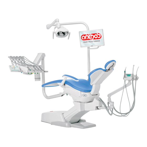
CONTINENTAL version instrument board d Doctor’s console e Tray holder Assistant’s board g Assistant’s control console h Utility service center Multifunction foot control Water to cup m Turnable and removable bowl n Autobalancing arm Canister for independent supply of instrument sprays and water to cup Load reduction plate. z ANTHOS R1.0. dental chair Model R7 INTERNATIONAL Description of equipment. a Hydrogroup b Adjustable arm c INTERNATIONAL version instrument board d Doctor’s console e Tray holder (optional) Assistant’s board g Assistant’s control console h Utility service center Multifunction foot control... - Page 11 Description of equipment. a Hydrogroup b Adjustable arm e Auxiliary tray holder Assistant’s board g Assistant’s control console h Utility service center Multifunction foot control Water to cup m Turnable and removable bowl n Autobalancing arm Canister for independent supply of instrument sprays and water to cup X-ray film viewer for panoramic x-rays (optional) Load reduction plate. z ANTHOS R1.0. dental chair Model R7 M CONTINENTAL Description of equipment. Adjustable arm CONTINENTAL version instrument board Doctor’s console Tray holder Assistant’s board Assistant’s control console Utility service center Multifunction foot control Self-balancing arm Canister for independent supply of instrument sprays and water to cup q Operating lamp support adjustable arm.
- Page 12 Model R7 M CART Description of equipment. Adjustable arm. INTERNATIONAL version instrument board mounted on height-adjustable cart Doctor’s console Tray holder table. Assistant’s board Assistant’s control console Utility service center Multifunction foot control Self-balancing arm. Canister for independent supply of instrument sprays and water to cup. p Height-adjustable cart q Operating lamp support adjustable arm. X-ray film viewer for panoramic x-rays (optional) Load reduction plate. z ANTHOS R1.0. dental chair Model R7 P Description of equipment. Adjustable arm. Tray holder table. Assistant’s board Assistant’s control console Utility service center Multifunction foot control Self-balancing arm. Bottle for supplying syringe on assistant's board q Operating lamp support adjustable arm. X-ray film viewer for panoramic x-rays (optional) Load reduction plate. z ANTHOS R1.0. dental chair...
-
Page 13: Dental Chair
- OPERATING INSTRUCTION 2.3. Dental chair Description of the chair a Headrest b Back c Push-button panel chair movements d Movable seat (optional) e Movable arm (optional) Operating times The operating and rest times are as follows: work 25 sec. - rest 10 min. Maximum weight capacity. The maximum chair capacity is 160 Kg. WARNING! Do not exceed this value. Warnings for use. WARNING: FOOT CRUSHING HAZARD Pay attention to the patient and the staff during dental chair descent (on both sides). -
Page 14: R7 Line Operating Unit Conversion
- OPERATING INSTRUCTION 3.1. R7 line operating unit conversion To convert the operating unit from the right-handed operator version to the left-handed operator version, proceed as follows: • First of all, set up the operatory unit for conversion by moving the backrest completely up, raising the dental chair at least more than half of its vertical stroke and placing the instrument board’s arm and body in the middle in relation to the dental chair seat so that it is out of the way. WARNING! At this point, shut off the operatory unit so that it cannot accidentally be turned on, creating hazardous situations. • Take off the cover (a) that protects the hydrogroup’s short support arm and blocks movement. • Lift the element ( k ) locking the short arm in place. NOTE: slightly move arms on their pivot points so as to make element release easier. -
Page 15: R7 M Line Operating Unit Conversion
- OPERATING INSTRUCTION 3.2. R7 M line operating unit conversion To convert an R7 M line operating unit from the right-handed operator version to the left-handed operator version, simply invert instrument’s table arm position with operating lamp support arm after having removed the anti-rotation stopper pin ( c ). Once both arms have been turned, insert anti- rotation stopper pin ( c ) back in place to lock the operating lamp support arm in the new position. Dental chair operation The dental chair can be moved as follows: • Chair seat up/down, • Back up/down with inclination of the chair seat (Tren- delemburg compensated), • 30° clockwise or counter-clockwise seat rotation (optional). -
Page 16: Emergency Devices
- OPERATING INSTRUCTION 4.2. Emergency devices WARNING! Use the devices below when movement of the equipment needs to be blocked: • Dental chair control buttons (a), (c) or (d). Pressing any dental chair button blocks all movements are blocked. • Foot control ( b ) Foot control actuation: all movements are blocked. -
Page 17: Dental Chair Control Panel
- OPERATING INSTRUCTION 4.4. Dental chair control panel Description of the buttons: Button to save dental chair functions Button to reach home position Button to reach rinse position Button to raise seat Button to retrieve programmed position “A” Button to raise back rest Button to retrieve programmed position “B” Button to lower seat Button to disengage dental chair seat brake Button to lower back rest (operative only with turnable seat) 4.5. Movable armrests (optional) Both arm rests are movable and can be turned downwards so that the patient can more conveniently get on and off the chair. WARNING! • Maximum weight supported by armrest: 68 kg. 4.6. Seat rotation (optional) The dental chair may be equipped with a pneumatic device that allows the seat to be turned 30° clockwise or counter-clockwise to give the doctor or assistant more free space under certain work conditions. -
Page 18: Instrument Board Operation
- OPERATING INSTRUCTION Instrument board operation Layout of instruments. The positions the instruments are placed in on the board are determined by the customer at the time of order. Starting the instruments. • The syringe is always on (see paragraph 5.3.). • The curing light is turned on with the key when the instrument is withdrawn (see paragraph 5.7.) • Intraoral camera turn on when the instrument is extracted (see paragraph 5.8.). • If connected to an external PC, the integrated ZEN-Xi sensor is always operative (see paragraph 5.9.). • Once picked up, all the instruments are operated with the foot control. (see paragraph 5.2.). Simultaneous use of the instruments. A device sees that the instruments cannot be used simultaneously. The first instrument removed is operative while those removed there after are deactivated by this device. This device allows the chuck to be replaced in one instrument while another is used on the patient. Putting the instrument board place. The instrument board can be moved in all directions. To adjust the height of the board and/or direct it horizontally, simply grasp the handle ( a ). NOTE (only for pantograph arm with pneumatic brake): to adjust the height of the dentist’s instrument board, you first need to press the brake release button NOTE model R7 CART / R7 M CART: o adjust the height of... - Page 19 - OPERATING INSTRUCTION Inverting the console unit position for left-handed operators WARNING! BEFORE CARRYING OUT THIS OPERATION, TURN OFF THE DENTAL UNIT. DO NOT REMOVE THE CONSOLE FROM THE DENTIST’S MO- DULE IF THE DENTAL UNIT IS ON. To invert the position of the console unit on the dentist’s module, operate as follows: • Remove the console unit after unscrewing the fastening ring nut ( g ) by turning it anticlockwise.
-
Page 20: Doctor's Control Console
- OPERATING INSTRUCTION 5.1. Doctor’s control console The R7 series dental units have a R7 “hybrid” dentist’s console consisting of a membrane pushbutton panel and a resistive touchscreen display. 4.3” Wide colour TFT display with LED backlighting, resolution 480x272 pixels and 262k colours. Pushbutton panel for the following models: R7 CONTINENTAL R7 M CONTINENTAL Pushbutton panel for the following models: R7 INTERNATIONAL R7 M INTERNATIONAL R7 CART R7 M CART Description of the buttons: Dentist’s instrument board brake release button (INTERNATIONAL models) SMART TOUCH screen disable button... - Page 21 - OPERATING INSTRUCTION Warning icons. Touching the icon button on the touch display, you can at any time view the warning icons that show the operating status of the dental unit. The warning icons viewable are the following: Feeding with distilled water activated. Feeding with mains water activated. Distilled water level low. ( excluding models R7 M ) BIOSTER cycle in progress. Suction tubes being washed. Suction stopped due to full canister. Wireless foot control battery charged. Wireless foot control battery 50% charged. Wireless foot control battery flat. Wireless foot control connected and active. Wireless foot control connected but not active. Searching for connection to the wireless foot control. Dental chair seat brake released (only with turnable seat ). Rinse automated programme chair position. COLD water-to-glass. Home automated programme chair position. WARM water-to-glass. Emergency automated programme chair position. HOT water-to-glass. Dental chair save function on.
-
Page 22: User Interface
TIME AND DATE SETTING. 5.1.1.2.7. CHRONOMETER. 5.1.1.2.7. 5.1.1.2.8. FAVOURITE BUTTONS CUSTOMISATION. 5.1.1.2.9. OPERATOR DATA ENTRY. 5.1.1.2.10. LANGUAGE SELECTION. 5.1.1.2.8. 5.1.1.2.9. 5.1.1.2.10. Error messages. During the initial self-diagnostic cycle, the dental unit may detect some mal- functions in the internal system. In this case, an error message is shown on the display (see paragraph 10) which remains visible until the operator touches the TOUCH DISPLAY. If the malfunction is not hazardous, the dental unit will continue to operate. Stand-by mode. The dental unit goes into power saving mode (stand-by) after approximately 10 minutes of non-use; this mode is shown by the ANTHOS logo on the control panel display. Normal operating conditions are restored as soon as any operation is performed. -
Page 23: Operator Selection
- OPERATING INSTRUCTION 5.1.1.1. Operator selection The SMART TOUCH console of the R7 series dental units allows managing 3 different operators. The following data can be set for each operator: • Operator's name. • Turbine and scaler power adjustment. • 3 electric micromotor operating modes • 4 scaler operating modes . • Turning on and adjustment of the fibre optics of each instrument. • Incremental or ON/OFF control of the turbine and the scaler power . • Automatic dental chair movement programs. • Hydro unit configuration parameters Operator selection. From the main page, repeatedly touch the icon button until finding the desired operator. NOTE: the operator is changed cyclically. 5.1.1.2. General settings From the main page, carry out the following operations: • Touch the icon button to access the GENERAL SETTINGS menu containing the following icon buttons:... -
Page 24: Hygiene System Settings
- OPERATING INSTRUCTION 5.1.1.2.1. Hygiene system settings NOTE: menu available only if at least a hygiene system is present. From the GENERAL SETTINGS menu touch the icon button to access the HYGIENE SYSTEM SETTINGS submenu containing the following icon buttons: BIOSTER /S disinfection cycle setting (only if the BIOSTER /S system is present ) Flushing CYCLE SETTING... -
Page 25: 5.1.1.2.1.2. Flushing Cycle Setting
- OPERATING INSTRUCTION 5.1.1.2.1.2. Flushing CYCLE SETTING This setting is shared by all users. From the HYGIENE SYSTEM SETTINGS menu carry out the following operations: • Touch the icon button to access the FLUSHING CYCLE SETTING submenu . NOTE: this submenu cannot be entered if the distilled water tank is low (see paragraph 7.2.). A message on the control panel display and an acoustic signal (BEEP) will signal the impossibility to enter the submenu. -
Page 26: Hydro Unit Settings
- OPERATING INSTRUCTION 5.1.1.2.2. Hydro unit settings From the GENERAL SETTINGS menu touch the icon button to access the HYDRO UNIT SETTINGS submenu containing the following icon buttons: Water to bowl settings Water to cup settings Automatic bowl movement setting (only with motor-driven bowl) 5.1.1.2.2.1. Bowl water delivery setting From the HYDRO UNIT SETTINGS menu touch the icon button access the BOWL WATER SETTING submenu containing the following icon buttons: Bowl flushing controller with dental chair brought to rinse position Bowl flushing controller with dental chair brought to reset position Cuspidor bowl flushing automatism with return from the rinse position for the chair A Bowl flushing controller with cup call Setting of timed or ON/OFF bowl flushing Bowl flushing time (in seconds ) • To select/deselect a function, touch the relative icon button. •... -
Page 27: 5.1.1.2.2.2. Cup Water Delivery Setting
- OPERATING INSTRUCTION 5.1.1.2.2.2. Cup water delivery setting From the HYDRO UNIT SETTINGS menu touch the icon button to access the CUP WATER SETTING submenu containing the following icon buttons: COLD cup water selection WARM cup water selection HOT cup water selection Cup water delivery time (in seconds ) Cup water delivery automatic function with rinse position recall. Cup detection sensor activation/deactivation ( only if the cup sensor is present ) Distilled water tank depressurization automatic function with chair home position recall • To select/deselect a function, touch the relative icon button. • To change the cup water delivery time, touch the icon buttons NOTE: the cup time of filling can be set up from a minimum of 1 second to a maximum of 10 seconds with increments of 0.1 seconds. • To confirm the selected settings, exit this submenu by touching the icon button 5.1.1.2.2.3. -
Page 28: Foot Control Adjustment
- OPERATING INSTRUCTION 5.1.1.2.3. Foot control adjustment From the GENERAL SETTINGS menu touch the icon button access the FOOT CONTROL ADJUSTMENT submenu containing the following icons: Cable connection icon (only with wireless foot control) Wireless connection status icon (only with wireless foot control) Battery percentage charge icon (only with wireless foot control) Foot control joystick operation setting with instrument removed NOTE: the first 3 icons are just for signalling, while the fourth one al- lows to select/deselect the operation mode of the foot control upper joystick. -
Page 29: Other Settings
- OPERATING INSTRUCTION 5.1.1.2.5. Other settings These settings are unique for all the operators. From the GENERAL SETTINGS menu touch the icon button to access the OTHER SETTINGS containing the following icon buttons: Touch display acoustic signal activation/deactivation Dental chair movement activation/deactivation Display brightness adjustment • To activate or deactivate an acoustic signal each time the TOUCH DI- SPLAY is touched. • To enable/disable the dental chair movements, touch the relative icon button. NOTE: when the chair is locked, it is indicated by a dedicated icon on the TOUCH DISPLAY (see paragraph 5.1.). -
Page 30: Chronometer
- OPERATING INSTRUCTION 5.1.1.2.7. Chronometer This setting is shared by all users. From the GENERAL SETTINGS menu touch the icon button to access the CHRONOMETER SUBMENU. • To change the various data displayed , touch the relative icon buttons NOTE: the time can bet set from 00:00:00 to 10:59:59. • Once you have set the time, touch the icon button to start the countdown. -
Page 31: Operator Data Entry
- OPERATING INSTRUCTION 5.1.1.2.9. Operator data entry From the GENERAL SETTINGS menu touch the icon button access the OPERATOR DATA ENTRY submenu. NOTE: the data modified always refers to the operator set on the main page. • To enter the desired text, touch the icon buttons of the various letters (max. 20 characters). • To enter capital letters, touch the icon button • To enter numbers or special characters, touch the icon button • To cancel any typing mistakes, touch the icon button cancelling from left to right. • Once you have entered the text, touch the icon button to exit from the submenu and automatically save the data. -
Page 32: Programming The Chair Positions A, B, C And D
- OPERATING INSTRUCTION 5.1.3. Programming the chair positions A, B, C and D This setting is specific for each operator. Perform the following operations from the main screen: • Bring the dental chair into the desired position with the manual movements buttons. NOTE: the position of the bowl can be saved, if powered. • Hold button “SAVE” for at least 2 seconds to activate memory mode. NOTE: Storage mode activation is signalled by a short beep and by the dedicated icon ( A ) on the TOUCH DISPLAY. -
Page 33: Foot Control
- OPERATING INSTRUCTION 5.2. Foot control 3 types of foot controls are available: "Multifunction” foot control "Push-pedal” foot control "Power Pedal" foot control. NOTE: the "multifunction" and "pressure" foot controls can also be supplied in wireless version. 5.2.1. "Multifunction” foot control Description of the parts Handle Control pedal Dental chair movements Chip-air/patient rinsing position control. Water Clean System/Automatic dental chair return control. LED (not active). Battery charge LED (wireless version only). Joystick for dental chair movement (3). With instrument removed • Starts the instrument. -
Page 34: Push-Pedal" Foot Control
- OPERATING INSTRUCTION Left-hand button operation ( 4 ). • Key held down (at least 2 seconds) with the instrument removed: Chip-air operation: delivers air to the turbine or micromotor. Air is delivered by pressing the button. Air is no longer blown when the button is released. • Key held down (at least 2 seconds) with the instruments in place: "Rinse position” (PR) program activated. NOTE: Press the key again to bring the chair back to the work position. Right-hand button operation ( 5 ) •... - Page 35 - OPERATING INSTRUCTION Joystick for dental chair movement (3). These buttons move the dental chair as follows: Dental chair seat up. Dental chair backrest up. Dental chair seat down. Dental chair backrest down. To stop the chair movement, release the joystick. NOTE: All the buttons used to move the dental chair are inoperative when an instrument is removed and the foot control pedal is actuated. NOTE: the joystick operating mode can be changed with the instru- ment removed (see Paragraph 5.1.1.2.3.).
-
Page 36: Power Pedal" Foot Control
- OPERATING INSTRUCTION 5.2.3. "Power Pedal" foot control Description of the parts. 1 Handle. 2 Foot control. Dental chair movements. 4 Chip-air control or activation/deactivation of instrument spray function. 5 Water Clean System control or activation/deactivation of instrument spray function. 6 Automatic dental chair return or programme "B” recall activation. 7 Patient rinse position or programme "A" recall activation. 8 Spray operation LED. Foot control operation ( 2 ). • With instrument removed - Pushing the pedal ( a ), the instrument is started. The instrument's rpm (or power) can be adjusted by varying the pressure exerted on the foot control. - Page 37 - OPERATING INSTRUCTION Right lever operation ( 6 ). NOTE: the lever functions only with the instruments in their rest position. For safety reasons, the selected function starts only after the switch has been briefly actuated and then released. • Lever pushed down: "Dental chair automatic return” program activated. • Lever pulled up: Dental chair program “B" start. Left lever operation ( 7 ). NOTE: the lever functions only with the instruments in their rest position.
-
Page 38: Wireless Foot Control
- OPERATING INSTRUCTION 5.2.4. Wireless foot control The "multifunction" and "pressure" foot control can also be supplied in wireless version. The wireless foot control contains a ZIGBEE transmitter module (module certified for Europe, Canada and the USA). Warnings for use. WARNING! • Avoid keeping the wireless foot control in proximity of other RF sources, such as wireless LAN cards, other radio devices, home RF de- vices, microwave ovens. - Page 39 - OPERATING INSTRUCTION Recharging the battery. When the batteries in the WIRELESS foot control need to be recharged, operate as follows: • Open the protective cap of the connector on the rear of the foot control and connect the recharging cable. • Connect the other end of the recharging cable to the dental unit (see figure). At this point, the foot control, while it remains fully operational, will start recharging the battery ( Battery charging warning LED on ). NOTE: The battery is fully recharged in about 6 hours. WARNING! Exclusively use the dental unit to charge the battery of the WIRE- LESS foot control.
-
Page 40: Syringe
- OPERATING INSTRUCTION 5.3. Syringe Description of the instrument. [ a ] Nozzle. [ b ] Handpiece. [ c ] Syringe release button. [ d ] Air button. [ e ] Water button. [ f ] Hot/cold selector. [ g ] Hot/cold indicator light. Technical charachteristics. • Operating time: - 3F syringe: continuous operation, - 6F syringe: 5 sec. operation, 10 sec. rest. • Power supply: - 6F syringe (CEFLA s.c. models): 24 Vac; 50/60 Hz; 2 A; 50 W. • Classification in accordance with standard EN 60601-1: - 6F syringe (CEFLA s.c. models): CLASS II, type B. • Installation plan: consult the Technical Installation Manual (see Paragraph 11.). -
Page 41: Turbine
- OPERATING INSTRUCTION 5.4. Turbine Connecting the handpiece and changing the chuck. Refer to the specific instructions furnished with the handpiece. Use. WARNING! Read the instructions for use of the various turbines. • The cock ( f ) adjusts the water flow to the spray. • The cock ( e ) adjusts the amount of air spray for all the instruments. • Place the instrument in its work position. NOTE: instrument activation is indicated by the relative manage- ment page appearing on the TOUCH DISPLAY. • The icon buttons available on the TOUCH DISPLAY are the following: Settable value increase Settable value decrease... - Page 42 - OPERATING INSTRUCTION Turbine rotation speed change. With the instrument in working position, select turbine speed change mode by touching the following icon buttons: Linear change proportional to the movement of the the foot control lever ON/OFF change that results in delivery of the maximum power set upon activation of the foot control lever The active mode icon is shown on the TOUCH DISPLAY. NOTE: the data is automatically stored. Instrument spray control button. With the instrument in working position, select the type of spray delivered by the instrument by touching the following icon buttons: Water + air spray operation Water-only spray operation Operation without spray The change is cyclic each time the button is touched and the active mode icon is shown on the TOUCH DISPLAY. NOTE: the data is automatically stored. Removable cord The turbine has a removable cord to ease cleaning (see paragraph 5.). Cleaning and care.
-
Page 43: Micromotor
- OPERATING INSTRUCTION 5.5. Micromotor Coupling the handpieces and changing the chuck. Refer to the specific instructions furnished with the micromotor and various handpieces. Use. WARNING! Also read the instructions for use of the various motors. The instrument is supplied non-sterile. • Operating time: work 5 min., rest 5 min. • The cock ( f ) adjusts the water flow to the spray. - Page 44 - OPERATING INSTRUCTION Instrument spray control button. With the instrument in working position, select the type of spray delivered by the instrument by touching the following icon buttons: Water + air spray operation Water-only spray operation Operation without spray The change is cyclic each time the button is touched and the active mode icon is shown on the TOUCH DISPLAY. NOTE: the data is automatically stored. Rotation speed change mode selection. With the instrument in working position, select rotation speed change mode by touching the following icon buttons: Linear change proportional to the movement of the the foot control lever ON/OFF change that results in delivery of the maximum power set upon activation of the foot control lever The active mode icon is shown on the TOUCH DISPLAY. NOTE: the data is automatically stored. Micromotor rotation direction inversion. Select the micromotor rotation direction by touching the relative icon button: Normal rotation direction Inverted rotation direction...
- Page 45 - OPERATING INSTRUCTION Reduction ratio selection. Using the icon buttons you can select the desired reduction ratio from those stored. The torque value (set or current) is expressed in % or Ncm for the certified reduction gears. WARNING! An icon appears next to the torque value identifying the reading tolerance on the value indicated: tolerance of ±10% tolerance of ±20%. NOTE: the data is automatically stored. Removable cord The micromotor has a removable cord to ease cleaning (see paragraph 5.).
-
Page 46: Restorative Operating Mode
- OPERATING INSTRUCTION 5.5.1. RESTORATIVE operating mode RESTORATIVE operation characteristics - speed adjustable from 100 to 40000 RPM (handpiece 1:1 ), - Rotation speed change mode settable from variable to fixed and vice versa - Alarm signal when the maximum torque is reached - Fast capture of the maximum speed during motor rotation. Menu with micromotor extracted but not active. All the icon buttons are active and each function available can be changed (see paragraph 5.5.). NOTE: each setting or value changed will automatically be stored in the operating program selected (e.g. P1). Menu with micromotor extracted and active. - Page 47 - OPERATING INSTRUCTION Menu with micromotor extracted and active. The modifiable functions are the following: • Maximum drill rotation speed using the icon buttons • Current speed freezing using the following icon button: Sets the current rotation speed as maximum speed • Foot control lever change mode using the following icon buttons:ù Sets the current rotation speed as maximum speed at the same time activating a function to change the foot control lever ON/OFF mode Switches the foot control lever change mode from ON/OFF to linear...
-
Page 48: Scaler
- OPERATING INSTRUCTION 5.6. Scaler Connecting the handpiece and inserts. Refer to the specific instructions furnished with the handpiece. WARNING! Before attempting to connect the handpiece, make certain the contacts are perfectly dry. Blow air from the syringe, if necessary, to dry Use. • Operating times: see operating instructions supplied with the handpiece. • The cock [ f ] adjusts the cooling water flow. • Place the instrument in its work position. - Page 49 - OPERATING INSTRUCTION Scaler power change mode selection. With the instrument in working position, select scaler power change mode by touching the following icon buttons: Linear change proportional to the movement of the foot control lever ON/OFF change that results in delivery of the maximum power set upon activation of the foot control lever The active mode icon is shown on the TOUCH DISPLAY. NOTE: the data is automatically stored. Cooling water enable. With the instrument in working position, select whether or not water should be delivered by the instrument by touching the following icon buttons: Operation with water Operation without water The change is cyclic each time the button is touched and the active mode icon is shown on the TOUCH DISPLAY. NOTE: during operation without water, the maximum power delivered is 50% of the maximum power settable. NOTE: the data is automatically stored.
- Page 50 - OPERATING INSTRUCTION Removable cord The scaler has a removable cord to ease cleaning (see paragraph 5.). Cleaning and care. Refer to the specific instructions furnished with the instrument. WARNING! • Do not soak the handpiece in liquid disinfectants or detergents. Sterilization. • Torque wrench, scaler bits and scaler handpiece: steam autoclave at 135°C (2 bar) following the instructions for use of the device. WARNING! Carefully read the operating instructions supplied with the instrument before attempting to sterilize. Instructions for use. WARNING! • The instrument is supplied NOT STERILE and must be sterilized before use (see paragraph 1.5.).
-
Page 51: T Led Curing Light
- OPERATING INSTRUCTION 5.7. T LED curing light (not available for the American and Canadian markets) Technical specifications. Supply voltage: 24-36 VDC Max. power absorbed: 6 VA Light source: 1 5W LED Wavelength: 430-490 nm Acoustic signals: at cycle start, every 5 seconds, and at cycle end Type of operation : intermittent (3 consecutive cycles - 60 sec. rest) Programs: 6 (preset) General description of the light a) Light handpiece b) Rotary end section c) Fiber optic d) Eye protection e) Power cord Start button NOTE: The curing light can be used in different configurations (wand, gun or any intermediate position) to aid the user. - Page 52 - OPERATING INSTRUCTION • Take the light out of its housing on the assistant’s board or instrument board. NOTE: instrument activation is indicated by the relative management page appearing on the TOUCH DISPLAY. • Turn the front of the light and/or fiber optic to the position most suitable for curing (wand, gun or intermediate position). • Use the MODE button to select the desired cycle as previously directed (the selected cycle is always indicated by the illuminated LED). NOTE: The curing light has a permanent memory therefore the last cycle used will always be present the next time it is used. • Place the fiber optic in the position required for curing.
- Page 53 - OPERATING INSTRUCTION Safety guidelines. WARNING! • The LED is a Class 2 light source in accordance with IEC 62471. DO NOT FIX THE BEAM. The light emitted may cause eye damage in the event of direct radiation without eye protection. Eye protection must always be worn when using the curing lamp and do not direct the light beam in eyes. The light emitted may damage soft tissues (oral cavity mucous, gums, skin). Be extremely careful to direct the light precisely on the material to be cured. • People with eye diseases, such as those who have had cataracts removed or retina diseases must be adequately protected when the curing lamp is used, for example with s uitable protective eyewear.
-
Page 54: C-U2 Dental Camera
- OPERATING INSTRUCTION 5.8. C-U2 dental camera The C-U2 dental camera system, complete with an extremely lightweight ergonomic handpiece, is specially designed for simple and well-conceived usability in examining the oral cavity. Auto-exposure and fi xed focus features provide easy operation. This system is designed to allow the dentist to more effi ciently show and explain to patients all oral conditions and reasons for planned treatment. The C-U2 system allows fi lming and taking high-defi nition (1280x720) live images of the section in question to be taken through a touch of a fi ngertip on the touch-sensitive area of the handpiece. The live intraoral images are displayed on the monitor or Personal Computer. WARNING! The camera may be used as a diagnostic tool however the results are to be compared to direct observation and/or other diagnostic means. Diagnosis based solely on the image obtained by the camera may result in poor evaluation as the electronically processed colors and shapes, may not correspond to those truly present. - Page 55 - OPERATING INSTRUCTION • Briefly press the foot control to stop from 1 to 16 images divided in 4 pages on the monitor. NOTE: The images shown on the monitor by the camera are only temporarily saved. To permanently save the images, connect the camera to a PC that complies to standard IEC 60950 which has a USB 2.0 HIGH SPEED port and image software program.
- Page 56 - OPERATING INSTRUCTION Operation in single image mode. Take out the camera in LIVE mode and set to single image mode, the “live” image appears on the monitor: • Tap the touch button [ g ] on the camera’s handpiece (or actuate the foot control) to freeze the image which is immediately displayed on the monitor, deleting any previous images. • Touching the icon button the last frozen image is displayed. NOTE: The last image frozen remains on the monitor even if the camera is put back in place. Operation in multiple image mode Extracting the camera in LIVE mode and in multiple image mode, a “moving” image is shown on the display, and in the top right corner the icon with the number of the active storage page appears (e.g. 1): • Touch the icon button...
- Page 57 - OPERATING INSTRUCTION Handpiece status. An optical guide, illuminated by a multicolour LED indicator, found in the area near the control button (h), shows handpiece status as per the table given below: Color Situation Blue light fl ashes, very slowly Handpiece in standby Handpiece activated, live images Light blue steady light displayed Blue/ light blue fl ashing light Handpiece in image freeze mode Internal error: contact Customer Ser- Brief red fl ashes vice MyRay Capture This program allows the C-U2 camera to be set up when it is connected to a PC/WORKSTATION. For a full description on how the MyRay iCapture program works, refer to the instructions, in electronic format, supplied with the C-U2 handpiece. Disposable infection control sheaths The camera can be a vehicle of cross-contamination between patients. For this reason always use it with a disposable infection control sheath (code 97901590) and disinfect it on the outside after use everyday . The sheath (with white paper backing) is enclosed in two protective layers: a transparent one with blue tab at the front and a paper one at the back. Follow the directions below to install a new infection control sheath: 1. Insert the camera handpiece tip between the layer with white tab and the rear paper backing. The lens, surrounded by the LEDS, must face downwards towards the rear paper layer. Gently push the handpiece...
-
Page 58: Zen-Xi Integrated Sensor
- OPERATING INSTRUCTION 5.9. ZEN-Xi integrated sensor Integrated sensor ZEN-Xi is a medical device employed to acquire intraoral x-rays in an electronic format with a Personal Computer interface device. When used together with dental practice management software, the x-ray pictures can be saved in the patient's folder and viewed on the desktop pc monitor at a later time. WARNING! Do not use the system for any other purpose different from acquisition of intraoral x-rays and do not use it if you are not a professional in the dental and radiology fields. Use. Use and care instructions for integrated sensor ZEN-Xi are enclosed with the apparatus. NOTE: Integrated sensor ZEN-Xi does not interact with the dental unit from an electric point of view. -
Page 59: Assistant's Board Operation
- OPERATING INSTRUCTION Assistant’s board operation Main features: • Two articulated arms secure the board (a) to the hydrogroup (b) allowing it to be placed in the most convenient work position. The fixed arm (c) can turn 120° around the bowl. The pantograph arm (e) allows the assistant’s board to be moved 335 mm vertically through 6 work positions. NOTE: to completely lower the assistant’s board, simply move it all the way up and then lower it. • The assistant’s board (a) comes with a control console (d) with buttons used to operate the dental chair and hydrogroup. • The assistant’s module may be equipped with 2 suction cannulae and 2 instruments. • The assistant’s board comes with sliding rollers (f) that guide and hold up the suction tubes. NOTE: the assistant’s board is equipped with a safety device that locks out dental chair movement when the board’s arms are obstructed. -
Page 60: Syringe On Assistant's Board
- OPERATING INSTRUCTION 6.2. Syringe on assistant’s board For detailed information regarding operation of this instrument see para- graph 5.3. 6.3. Curing lamp on assistant’s board For detailed information regarding operation of this instrument see para- graph 5.7. 6.4. Intraoral camera on assistant’s board For detailed information regarding operation of this instrument see para- graph 5.8. -
Page 61: Suction Tubes
- OPERATING INSTRUCTION 6.5. Suction tubes Suction starts by taking the tube off the board. To adjust suction, use the slider ( a ) located on the tube handpiece. NOTE: When the tube is put back in place, suction stops approxi- mately 2 seconds later. This is done to dry the suction tubes. Cleaning the suction tubes. As the dental units may be equipped with different suction systems (liquid ring or wet, air) carefully follow the instructions provided by the suction system manufacturer when disinfecting the system regarding the product to be used, times and directions for use. -
Page 62: Hydraulic Saliva Ejector
- OPERATING INSTRUCTION 6.6. Hydraulic saliva ejector The hydraulic saliva ejector starts running when the tube is removed from the support. Cleaning after each use. Aspirate about ½ litre of STER 3 PLUS (CEFLA s.c.) diluted in a 6% solution (equivalent to 60 ml of product in 1 litre of water). Cleaning the saliva ejector filter This operation must be carried out at the end of each work day. WARNING! Put on gloves before attempting to perform this operation! • Aspirate about ½ litre of STER 3 PLUS diluted in a 6% solution (equivalent to 60 ml of product in 1 litre of water). • In order to prevent possible dripping of liquids and secretions from the filter ( b ) to be extracted, aspirate only air for about 5 seconds. • Take off the cap ( a ) by turning and twisting at the same time. • Remove the filter ( b ). • Clean/replace the filter (code 97290060). • Put the filter and cap back in place. Routine maintenance Lubricate the o-rings ( c ) with S1 – Protection for o-rings lubricant. -
Page 63: Hydrogroup Operation
- OPERATING INSTRUCTION Hydrogroup operation 7.1. Fill cup and bowl The bowl can freely move 305° on the hydrogroup. The bowl may be po- wered (optional) or can be turned by hand. The bowl and water to cup spout can be removed to ease cleaning. Control buttons. Water to cup button. Bowl flush button. Cup sensor. You can have an optical sensor fitted at the base of the cup fountain, which detects the cup and automatically activates filling. The sensor operates as follows: • 2 seconds after positioning the cup under the fountain, it is filled with water for 2 seconds (this time is not modifiable) • Once the cup has been removed, the filling cycle can be repeated only after 3 seconds • During the filling cycle, removing the cup and/or pressing the “CUP WATER DELIVERY” button, the water delivery cycle will immediately be interrupted. - Page 64 - OPERATING INSTRUCTION Taking off the bowl filter and rinse spout. • Pull up the spout ( l ) and take it off. • Pull up the filter ( q ) and its cover ( p ) to remove them. • Turn the bowl ( m ) counter-clockwise to release it and then pull it up to take it out. Disinfecting and cleaning. WARNING! Always wear gloves to prevent contact with infected material when cleaning the bowl and bowl filter. The parts are to be cleaned daily at the end of each work day. • Spouts and bowl: thoroughly wash with a specially formulated cleaner (for example MD 550 Orotol DÜRR). • Bowl filter: clean with running water and commercially-available cleaning products. WARNING! Do not use acids or harsh products.
-
Page 65: S.h.s./S System ( Semplified Hygienization Sistem )
- OPERATING INSTRUCTION S.H.S./S system ( Semplified Hygienization Sistem ) Models R7 CONTINENTAL, R7 INTERNATIONAL and R7 CART. Description of the system The system S.H.S. /S is equipped with a distilled water tank ( a ). The tank can hold 1.8 liters. Distilled water is delivered to: • the sprays of all the instruments found on the instrument and assistant’s board. • the syringe on the assistant’s board. • to fill the cup • water quick-connect coupler (if present) The icon button on the TOUCH DISPLAY (see paragraph 5.1.1.2.8.) allows activating/deactivating the SHS/S system. NOTE: the distilled water delivery status is shown by the icon ( A ) on the control panel display. Tank reserve level. -
Page 66: Manual Shs System
- OPERATING INSTRUCTION 7.3. Manual SHS system Models R7 IDRICO SINGOLO, R7 M CONTINENTAL, R7 M INTERNATIO- NAL, R7 M CART and R7 P. Description of the system The system comes with a canister (a), placed on the instrument board support arm, that contains distilled water. The tank can hold 1.8 liters. The tank feeds: • the sprays of all the instruments found on the instrument and assistant’s board. • The syringe on the assistant’s board. • to fill the cup • water quick-connect coupler (if present) A by-pass lever (b), placed on the side of the canister, is used to shut off the system if municipal water is to be supplied to the instruments. WARNING! With the manual SHS system, the tank reserve ( a ) and SHS system active/inactive warning icons are not shown on the TOUCH DISPLAY. -
Page 67: Disinfection Cycle With Oxygenated Water
- OPERATING INSTRUCTION 7.3.1. Disinfection cycle with oxygenated water With the S.H.S. system, you can execute a manual disinfection cycle of the water ducts of all the instruments on the dentist’s instrument board and the syringe on the assistant’s board using oxygenated water (hydro- gen peroxide). To disinfect, proceed as directed below: A) Prepare the disinfectant: • Pour undiluted PEROXY Ag+ (not available for the American and Canadian markets) (or 3% oxygenated water) into the tank marked with an orange band. NOTE: make sure that the tank is completely filled. B) Putting in the disinfectant: • Check that the spray tap of each dynamic instrument is completely open (if not, no or too little water will come out). -
Page 68: Bioster/S Automatic Disinfection System
- OPERATING INSTRUCTION 7.4. BIOSTER/S automatic disinfection system Models R7 CONTINENTAL, R7 INTERNATIONAL and R7 CART. Description of the system. The BIOSTER S system allows running a disinfection cycle of the water ducts of all the instruments on the dentist’s instrument board, of a dynamic instrument on the assistant's board and of the cup water delivery ducts. To run the disinfection cycle, operate as follows: A) Preparing the disinfectant solution: • Pour undiluted PEROXY Ag+ (not available for the American and Ca- nadian markets) (or 3% oxygenated water) into the tank marked with an orange band. - Page 69 - OPERATING INSTRUCTION Interrupting the disinfection cycle. The syringe on the assistant's board cannot be disinfected using the BIOSTER S cycle. NOTE: once the cycle has been activated, it CANNOT be interrupted. PEROXY Ag+ storage. For proper storage of PEROXY Ag+ follow the manufacturer’s instructions printed on the package. It is important to keep the package tightly closed and store it in a cool place at a temperature not exceeding 25°C. WARNING! Never leave PEROXY Ag+ or oxygenated water in the tank ( a ) for longer than one month. If you are going to be absent from the surgery for long periods of time (holidays), completely empty out the tank ( a ) before leaving.
-
Page 70: Automatic Instrument Flushing Cycle (Flushing)
- OPERATING INSTRUCTION 7.5. Automatic instrument FLUSHING CYCLE (FLUSHING) Description of the system. The automatic FLUSHING cycle allows to carry out an automatic flushing cycle to renew water present in the water ducts of the instruments on the dentist’s and the assistant’s boards and the water-to-cup duct. Flushing may be carried out with mains water, treated water or distilled water (if the S.H.S. system is present). The cycle duration can be set up from 1 to 5 minutes. WARNING! It is advisable to carry out a FLUSHING cycle at the beginning of each working day and between two patients. Setting the FLUSHING cycle. -
Page 71: Acvs System (Automatic Cleaning Vacuum System)
- OPERATING INSTRUCTION 7.6. ACVS system (Automatic Cleaning Vacuum System) Description of the system. This system allows cleaning the surgical suction system. The system comes with a tank ( c ) that contains the liquid disinfectant and two fittings ( d ) used to wash the suction tubes. The detergent liquid tank has a total capacity of 250 cc. The washing cycle is automatically carried out and should usually be performed at the end of each surgical procedure and whenever the dental unit is cleaned and disinfected. WARNING! It is recommended to use STER 3 PLUS (CEFLA s.c.) as detergent liquid, diluted in a 6% solution (equivalent to 60 ml of product in 1 litre of water). -
Page 72: Opening/Closing The Side Hydrogroup Cover
- OPERATING INSTRUCTION 7.7. Opening/closing the side hydrogroup cover Opening the cover. • Open the cover on the side of the hydrogroup (a) after pushing up and releasing the lock lever (b). Closing the cover. • Put on the cover making sure the two locks are inserted in the notches in the hydrogroup. • Lastly, bring the bottom of the cover near the hydrogroup frame to engage the lock lever again. -
Page 73: Accessories
Lamp with LED light source – model VENUS PLUS-L. The instructions for use and maintenance of the lamps are available in PDF format and can be downloaded from the download area of the website www.anthos.com. NOTE: During the automatic movements of the dental chair, the lamp automatically turns off to prevent blinding the patient. -
Page 74: Auxiliary Tray Holder
- OPERATING INSTRUCTION 8.5. Auxiliary tray holder Models R7 CART, R7 M CART, and R7 P. The instrument tray holder can hold two standard size trays. Turn the knob ( b ) to adjust vertical movement according to the weight. • turn clockwise to increase resistance (heavy loads). • turn counter-clockwise to decrease resistance (light loads). WARNING! Maximum allowable load on tray 3.5 Kg (no x-ray film viewer) or 2.5 Kg (with x-ray film viewer) -
Page 75: Maintenance
- OPERATING INSTRUCTION Maintenance Preventive maintenance CEFLA s.c., the manufacturer of the dental units, in accordance with applicable standards IEC 60601-1 3.a Ed. - 2007, IEC 62353 and directive MDD 93/42, and subsequent changes, for medial devices underlines that the preventive maintenance checks for the dental unit specified in the Technical care manual and Maintenance and warranty handbook are to be carried out by authorised personnel at least once every 12 months. ATTENZIONE! The warranty is void if the equipment is serviced, repaired, altered or modified in any way by personnel who have not been duly authorized by CEFLA s.c.. Safety checks. In accordance with standard IEC 62353, the safety checks specified in the Technical care manual and Maintenance and warranty handbook supplied with the dental unit are to be carried out at the intervals required by current local regulations. If no precise indications are given, CEFLA s.c., the manufacturer of the dental units, recommends checking them at least every 24 months at the time of installation and whenever electrical parts that are live are repaired/updated. WARNING! The manufacturer shall not be held liable for any personal injury or equipment damage if the precautions given above are not observed. 9.1. -
Page 76: Surgical Suction
- OPERATING INSTRUCTION 9.4. Surgical suction The surgical suction system must be sanitized using a product suitable for this purpose. WARNING! For cleaning of the suction system, it is recommended to use STER 3 PLUS (CEFLA s.c.) diluted in a 6% solution (equivalent to 60 ml of product in 1 litre of water). At the end of each surgical procedure. -
Page 77: Cattani Surgical Separator
- OPERATING INSTRUCTION 9.5. CATTANI surgical separator At the beginning of each work day. Insert inside filter ( d ) a tablet ( v ) of VF CONTROL PLUS (CEFLA s.c.) WARNING! Always wear gloves to prevent contact with infected material when carrying out this operation. At the end of each surgical procedure. • Execute an automatic flushing cycle or aspirate about ½ litre of sanitizing solution with each of the cannulas used. • Sterilize the cannula holder terminals in steam autoclave (see paragraph 1.5.). -
Page 78: Cleaning The Turbine Return Air Filter
9.8. DÜRR amalgam separator The maintenance instructions for the DÜRR amalgam separator are enclosed with the equipment if the equipment comes with this type of separator. The separator’s control device is located in the hydrogroup. WARNING! Always wear gloves to prevent contact with infected material when cleaning the separator. WARNING! When disposing one-time use containers full of amalgam, observe current local and national laws. 9.9. Dental chair The dental chair does not require any particular maintenance. It is nevertheless advisable to once a year have an authorised ANTHOS technician check overall functioning. -
Page 79: Fault Messages
- OPERATING INSTRUCTION Fault messages M = Message shown on console display C = Cause R = Remedy M: “Lower dental chair” M: “H2O level low, fill tank” C: The bowl does not move because the dental chair is in its way. C: The water in the independent water system's tank has dropped below R: Lower the dental chair so that it is no longer in the way. the minimum acceptable level. R: Fill the tank (see paragraph 7.2.). M: “Check operating light fuses” C: The operating light does not turn on because electric power is not M: “Put instruments back in place” supplied. C: The system detected an instrument was already withdrawn while the R: Call technical support. disinfecting cycle was being set. R: Make sure all the instruments are in place and then set the cycle again. M: “Maintenance required" If the fault message appears again, call technical support. -
Page 80: Specifications
- OPERATING INSTRUCTION 11. Specifications Installation plan: 97042064 Water usage: 2 l/min. Technical manual: 97071158 Water hardness: < 25 °f ( 14 °d ) Dental unit spare parts catalogue: 97023117 Drain connection: ø40 mm. Dental chair spare parts catalogue: 97023117 Drainage rate: 10 l/min. Maximum dental unit weight: 110 Kg. Drain duct inclination: 10 mm/m. Maximum dental chair weight: 140 Kg. Aspirator connection: ø40 mm. Maximum dental chair capacity: 160 Kg. Vacuum (minimum): 65 mbar. Voltage: 230V~ / 115V~ Vacuum delivery rate: 450 l/min. -
Page 81: Overall Dimensions: R7 Continental
- OPERATING INSTRUCTION 11.1. Overall dimensions: R7 CONTINENTAL 1886 PIASTRA ANTIRIBALTAMENTO ANTI-TURNOVER PLATE PLAQUE ANTI-RENVERSEMENT KIPPSCHUTZPLATTE PLACA ANTIBASCULACION 39 4 1822 2640... -
Page 82: Overall Dimensions: R7 International
- OPERATING INSTRUCTION 11.2. Overall dimensions: R7 INTERNATIONAL 1886 PIASTRA ANTIRIBALTAMENTO ANTI-TURNOVER PLATE PLAQUE ANTI-RENVERSEMENT KIPPSCHUTZPLATTE PLACA ANTIBASCULACION 17 0 1822 2640... -
Page 83: Overall Dimensions: R7 Cart
- OPERATING INSTRUCTION 11.3. Overall dimensions: R7 CART 1886 PIASTRA ANTIRIBALTAMENTO ANTI-TURNOVER PLATE PLAQUE ANTI-RENVERSEMENT KIPPSCHUTZPLATTE PLACA ANTIBASCULACION 1822 50 0 1957... -
Page 84: Overall Dimensions: R7 M Continental
- OPERATING INSTRUCTION 11.4. Overall dimensions: R7 M CONTINENTAL 1 886 PIASTRA ANTIRIBALTAMENTO ANTI-TURNOVER PLATE PLAQUE ANTI-RENVERSEMENT KIPPSCHUTZPLATTE PLACA ANTIBASCULACION 1 70 1822 2500... -
Page 85: Overall Dimensions: R7 M International
- OPERATING INSTRUCTION 11.5. Overall dimensions: R7 M INTERNATIONAL 1886 PIASTRA ANTIRIBALTAMENTO ANTI-TURNOVER PLATE PLAQUE ANTI-RENVERSEMENT KIPPSCHUTZPLATTE 43 5 PLACA ANTIBASCULACION 1822 2640... -
Page 86: Overall Dimensions: R7 M Cart
- OPERATING INSTRUCTION 11.6. Overall dimensions: R7 M CART 1886 PIASTRA ANTIRIBALTAMENTO ANTI-TURNOVER PLATE PLAQUE ANTI-RENVERSEMENT KIPPSCHUTZPLATTE PLACA ANTIBASCULACION 1 7 0 1822... -
Page 87: Overall Dimensions: R7 P
- OPERATING INSTRUCTION 11.7. Overall dimensions: R7 P 1886 PIASTRA ANTIRIBALTAMENTO ANTI-TURNOVER PLATE PLAQUE ANTI-RENVERSEMENT KIPPSCHUTZPLATTE PLACA ANTIBASCULACION 1 70 1822... -
Page 88: Overall Dimensions: R7 Single Hydro Group
- OPERATING INSTRUCTION 11.8. Overall dimensions: R7 SINGLE HYDRO GROUP 1886 PIASTRA ANTIRIBALTAMENTO ANTI-TURNOVER PLATE PLAQUE ANTI-RENVERSEMENT KIPPSCHUTZPLATTE PLACA ANTIBASCULACION 1 7 0 1822 2640... -
Page 89: Dental Unit Maintenance Plan
- OPERATING INSTRUCTION Dental Unit maintenance plan WHEN PART SEE PARAGRAPH Condensate drain. See paragraph 9.2 Before starting work. Insert inside each suction tube filter a tablet of CATTANI surgical separator. See paragraph 9.5 VF CONTROL PLUS. See documentation enclosed Contra angle handpiece. Sterilize or disinfect the outside. with handpiece. Turbine. Sterilize or disinfect the outside. See paragraph 5.4 Micromotor. Disinfect outside. See paragraph 5.5 Scaler. Sterilize or disinfect outside. See paragraph 5.6 After each treatment.
Need help?
Do you have a question about the SMART TOUCH R7 and is the answer not in the manual?
Questions and answers