Table of Contents
Advertisement
Advertisement
Table of Contents

Related Manuals for LOMBARDINI MARINE Kohler KDI 1903TCR-MP


Summary of Contents for LOMBARDINI MARINE Kohler KDI 1903TCR-MP
- Page 1 KDI 1903TCR-MP KDI 2504TCR-MP OWNER MANUAL...
- Page 2 11/2018 Documentation Documentation Translated from the original manual in Italian language. Data reported in this issue can be modified at any time by Lombardini Marine. Important • Connect to http://iservice.lombardini.it and download the latest version of this manual onto your device.
-
Page 3: Table Of Contents
INDEX 1 - GENERAL INFORMATION 4 - INFORMATION ABOUT USE 1.1 Manual's purpose ............6 4.1 Pre-start check .............19 1.2 Glossary and Definitions ..........6 4.2 Break-in running ............19 1.3 Emission ................6 4.3 Starting and turning off ..........19 1.4 Service request ...............6 4.3.1 Starting ...............19 1.5 Engine component identification ........7 4.3.2 After starting ..............19... - Page 4 INDEX 7 - INFORMATION ABOUT FAILURES 7.1 Useful information about failures ........39 7.2 Error signals on the control panel .......40 8 - APPLICATION AND VALIDATION PROCESS 8.1 Application and Validation process for marine engine ... 41 8.2 Prescriptions to be respected ........42 9 - INFORMATION ABOUT WARRANTY Warranty terms ..............45 10 - GLOSSARY...
- Page 5 NOTES ................................................................................................................................................................................................................................................................................................................................................................................................................................................................................................................................................................................................................................................................................................................................................................................................................................................................................................................................................ED0053032450...
-
Page 6: Manual's Purpose
GENERAL INFORMATION 1.1 Manual's purpose • This manual contains the instructions needed to carry out change without notice and without obligation. proper use and maintenance of the engine, therefore it must • Kohler Engines reserves the right to make, at any time, always be available, for future reference when required. -
Page 7: Engine Component Identification
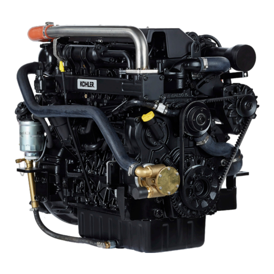
GENERAL INFORMATION 1.5 Engine component identification SIDE VIEW A Thermostat Oil filler cap Coolant refill cap Riser Air filter Turbocharger Coolant pump Water pump Oil pressure switch and sensor Starter motor Alternator SIDE VIEW B Intercooler Coolant temperature sensor Radiator Fuel injection pump Reversing gear Oil filter... -
Page 8: Manufacturer And Motor Identification Data
GENERAL INFORMATION 1.6 Manufacturer and motor identification data The engine identification nameplate is located on side A or B as below. SIDE VIEW A SIDE VIEW B Manufacturer identification Engine serial number Engine type CE certificate (*1) Peak Engine version Approval data and "EC"... -
Page 9: General Description Of The Engine
TECHNICAL INFORMATION 2.1 General description of the engine - 4-stroke, in-line cylinders Diesel engine; - Liquid-cooling system; - 4 valves per cylinder with hydraulic tappets; - Turbocharger with Waste-gate valve; - Direct injection. 2.2 Engine specifications UNIT TECHNICAL DATA MEASURE KDI 1903 TCR-MP KDI 2504 TCR-MP ENGINE TYPE... -
Page 10: Sae Oil Classification
TECHNICAL INFORMATION 2.4 Oil Danger Important • The engine may be damaged if operated with improper oil • Prolonged skin contact with the exhausted engine oil can cause cancer of the skin. level. • If contact with oil cannot be avoided, thoroughly wash your •... -
Page 11: Fuel
TECHNICAL INFORMATION 2.5 Fuel Warning Important • Clean fuel prevents the fuel injectors from clogging. • Use of other types of fuel could damage the engine. Do not Immediately clean up any spillage during refuelling. use dirty diesel fuel or mixtures of diesel fuel and water since •... -
Page 12: Non-Road Fuels
TECHNICAL INFORMATION 2.5.4 Non-Road Fuels Other non-road fuels may be used if they comply with all the limit values of EN 590 except for the fuel density, the cetane number and the sulfur content. The following limits apply for these parameters: FUEL PARAMETER UNIT LIMIT VALUE... -
Page 13: Control Panel
TECHNICAL INFORMATION 2.8 Control panel Tab. 2.7 shows the control panel components. POS. DESCRIPTION Panel ignition switch with key switch Engine on push button Engine rpm indicator Engine data or errors display Engine data or errors push button Maintenance errors reset push button Engine off push button Tab. -
Page 14: Safety Information
SAFETY INFORMATION 3.1 Safety information • The intended use of the engine is in conformity with the • Those who carry out the use and maintenance on the machine on which it is mounted. engine must wear the safety equipment and the accident- •... - Page 15 SAFETY INFORMATION • If there is an electric fan, do not approach the engine when • Do not mix fuel with elements such as oil or kerosene. it is still hot as the fan could also start operating when the Failure to comply with this prohibition will cause the non- engine is at a standstill.
-
Page 16: Safety Signal Description
SAFETY INFORMATION 3.3 Safety signal description • To ensure safe operation please read the following • This manual contains safety precautions which are statements and understand their meaning. explained below. • Also refer to your equipment manufacturer's manual for • Please read them carefully. other important safety information. -
Page 17: Information And Safety Signals
SAFETY INFORMATION 3.4 Information and safety signals HIGH PRESSURE FLUID ACCIDENTAL START RISK OF PUNCTURE Accidental Starts can cause High Pressure Fluids can severe injury death. puncture skin and cause severe injury or death. Before working on the engine or equipment, disconnect Do not work on fuel system without proper training or safety the battery negative (-) wire. -
Page 18: Location Of Safety Labels On Engine
SAFETY INFORMATION 3.6 Location of safety labels on engine ED0053032450... -
Page 19: Pre-Start Check
INFORMATION ABOUT USE 4.1 Pre-start check • Read carefully the following pages and carry out the operations described below in accordance with the instructions specified. Important • Non compliance with the operations described in the following pages involves the risk of damages to the engine and vehicle on which it is installed as well as personal and/ or property damage. -
Page 20: Refuelling
INFORMATION ABOUT USE 4.4 Refuelling Importan • Before proceeding with operation, read Par. 3.2.2. Danger • Fill the engine off. • The only approved fuels are those listed in Tab. 2.3. • In those countries where diesel has a high sulphur content, its is advisable to lubricate the engine with a high alkaline oil or alternatively to replace the lubricating oil recommended by Kohler Engines more frequently. -
Page 21: Reversing Gear Oil Top-Up
INFORMATION ABOUT USE 4.6 Reversing gear oil top-up • Before proceeding with operation, read Par. 3.2.2. Important • Place engine on horizontal surface to ensure accurate • For safety precautions see Par. 2.4. measurement of filling. 1. Loosen the oil filler cap A. 2. -
Page 22: Coolant Filling
INFORMATION ABOUT USE 4.7 Coolant filling Important Warning • Before proceeding with operation, read Par. 3.2.2. • An anti-freeze protection liquid (ANTIFREEZE) - mixed with • Place engine on horizontal surface to ensure accurate decalcified water - must be used. measurement of filling. -
Page 23: Useful Information About Maintenance
INFORMATION ABOUT MAINTENANCE 5.1 Useful information about maintenance • This chapter shows all operations described in the Tab. 5.1 Warning and Tab. 5.2 that may be directly carried out by the user. • Periodic inspection and maintenance operations must • Inspections must be made when the engine is off and cold. be carried out as indicated in this manual and are the •... -
Page 24: Oil Level Check
INFORMATION ABOUT MAINTENANCE 5.3 Oil level check Important • Place engine on horizontal surface to ensure accurate measurement of checking. 1. Loosen the oil filler cap A. Remove the oil dipstick B and check that the level is up to MAX. 2. -
Page 25: Rubber Hoses Check
INFORMATION ABOUT MAINTENANCE Danger • For safety precautions see Cap. 3. 5.4 Rubber hoses check The check is carried out by exerting a slight deflection or bending along the pipe and near the hose clamps. Components must be replaced if they have clear signs of cracks, tears, cuts, leaks and do not retain a certain degree of elasticity. -
Page 26: Check Coolant Level
INFORMATION ABOUT MAINTENANCE 5.5 Check coolant level NOTE: Before proceeding with any operation on the engine, stop it and allow it to cool. Important • Place engine on horizontal surface to ensure accurate measurement of checking. Warning • Presence of steam pressurized coolant danger of burns. 1. - Page 27 INFORMATION ABOUT MAINTENANCE 4. Loosen the clamps E of manifolds F and G. 5. Remove the manifolds from the components J and K. 6. Unscrew the screws H, remove the unit J and K. 7. Unscrew the screws L, separate the components J and K. 5.11 8.
- Page 28 INFORMATION ABOUT MAINTENANCE 10. Check the radiator P for any kind of encrustations and dirt. 11. Check all the holes on the surfaces P1, P2 for any kind of encrustations and dirt. NOTE: if the inner side of the hoses on the surfaces P1 and P2 are encrusted even after carrying out the cleaning in point 9, clean the hoses with specific mechanical...
- Page 29 INFORMATION ABOUT MAINTENANCE 17. Connect a suitable pump on the unions R to clean the ducts with a solution of distilled water and hydrochloric acid 10%, at a temperature of 50° C. 18. At the end of the cleaning operations in point 3, rinse with water only the inner side of the ducts using the pump as described in point 17.
- Page 30 INFORMATION ABOUT MAINTENANCE 23. Position the gasket Q4 on the intercooler U. 24. Insert the Intercooler U into the support V until it stops. 25. Insert the gasket Q5 on the intercooler U. 5.17 26. Fix the cap T1 on the support V with the screws M (tightening torque of 25 Nm).
-
Page 31: Check And Setting Alternator Standard Belt Tension
INFORMATION ABOUT MAINTENANCE 5.7 Check and setting alternator standard belt tension 5.7.1 Check 1. Check the belt A condition, if worn out or deteriorated, replace it. 2. Check by the appropriate tool that at point p the tension value is between 80 and 85 Hz. 3. -
Page 32: Product Preservation
INFORMATION ABOUT MAINTENANCE 11. When cleaning the engine, if using a pressure 5.9 Product preservation washer or steam cleaning device, avoid directing nozzle electrical components, cable connections sealed rings (oil seals etc). Important If cleaning engine with a pressure washer or steam •... -
Page 33: Unused Machine
INFORMATION ABOUT MAINTENANCE 5.13 Unused machine If the machine is not used for a certain amount of time, follow the operations below: 5.13.1 Operations for the engine 5.12 POINT OPERATION - The place must be dry and fresh throughout the period in which the machine is not used. unused ma- - Consult the machine’s manual to disconnect the battery (before disconnecting the battery, chine up to 2... -
Page 34: Engine Oil Replacement
INFORMATION ABOUT REPLACEMENTS Danger Disconnect the negative wire (-) from the battery to avoid accidental engine starting. Important Before proceeding with operation, read Par. 3.2.2 6.1 Engine oil replacement Important • Place engine on horizontal surface to ensure accurate measurement of oil level. •... -
Page 35: Oil Filter Cartridge Replacement
INFORMATION ABOUT REPLACEMENTS Warning • Oil filter cartridge replacement (Par. 6.2) fuel filter replacement (Par. 6.3) In case of low use replace it 12 months. 1. For disposal of oil filter cartridge and fuel filter refer 2. to Par. 6.8 DISPOSAL and SCRAPPING. -
Page 36: Fuel Filter Cartridge Replacement
INFORMATION ABOUT REPLACEMENTS 6.3 Fuel filter cartridge replacement Important • Do not fill the new cartridge B with fuel. • Replace the gaskets D and dampen them with oil. 1. Disconnect the cable A of the water presence sensor C. 2. -
Page 37: Alternator Belt Replacement
INFORMATION ABOUT REPLACEMENTS 6.5 Alternator belt replacement Important • Before proceeding with operation, carefully read Par. 3.3.2. 1. Loosen the screws A and B. 2. Push the alternator C in the direction of the arrow D and remove the belt E. 3. -
Page 38: Coolant Replacement
INFORMATION ABOUT REPLACEMENTS 6.6 Coolant replacement 1. Undo cap A to drain all liquid from the system contained in the engine crankcase ducts into an appropriate container (Par. 3.5). Important • Perform the operations described in Par. 5.6 before proceeding. •... -
Page 39: Useful Information About Failures
INFORMATION ABOUT FAILURES 7.1 Useful information about failures • This chapter contains information about the problems that may appear during engine operation with its causes and trouble shooting Tab. 7.2. • In some cases, you shall turn off the engine immediately to avoid further damage Tab. 7.1. 7.13 THE ENGINE MUST BE IMMEDIATELY TURNED OFF WHEN Warning RED light turn on... -
Page 40: Error Signals On The Control Panel
INFORMATION ABOUT FAILURES 7.2 Error signals on the control panel Tab. 7.3 shows the errors that can be generated on the control panel. 7.15 POS. DESCRIPTION Engine oil pressure low High coolant temperature Disabled alternator (with engine rpm < 850 rpm) Maintenance service (*1) Insufficient battery voltage (flashing display... -
Page 41: Application And Validation Process For Marine Engine
APPLICATION AND VALIDATION PROCESS 8.1 Application and Validation process for marine engine Kohler Engines educates his sales and service network in order to carry out the installation and commissioning of the engine with functional checks in respect of the standards established over the years and the requirements set out in the technical documents (owner manuals). -
Page 42: Prescriptions To Be Respected
APPLICATION AND VALIDATION PROCESS 8.2 Prescriptions to be respected During the installation operations, the following instructions must be observed: Compliance with the maximum inclinations permitted (owner manual) Engine below sea level with airvent valve installation scheme If sea water outlet is at height of less than 200 mm from the water line, fit an airvent system. - Page 43 APPLICATION AND VALIDATION PROCESS Fuel circuit connection scheme 1. Fuel supply shut-off valve on the tank 2. Fuel return shut-off valve on the tank 3. Fuel prefilter with water separator (10 micron) 4. Fuel cooler interposed on fuel return pipe on the tank Supports anti-vibration position and adjustment scheme ED0053032450...
- Page 44 APPLICATION AND VALIDATION PROCESS Connection and alignment to the axis line scheme Accurate alignment is done by adjusting the elastic supports and locking them when the correct position has been found. Engine and inverter must be aligned with the propeller shaft in two ways. The traditional measurement is made using a thickness gauge and the alignment can be considered correct when the measured value is within 0.125 mm.
-
Page 45: Warranty Terms
INFORMATION ABOUT WARRANTY KOHLER DIESEL ENGINES GLOBAL WARRANTY TERMS 1. WARRANTY PERIOD Kohler Co. warrants to the End User that each Diesel engine will be free from manufacturing defects in materials or workmanship in normal service for the applicable coverage period or operating hours (whichever comes first) set forth below, provided the engine is operated and maintained in accordance with Kohler Co.’s instructions and manuals. - Page 46 INFORMATION ABOUT WARRANTY IMPLIED OR STATUTORY WARRANTIES, INCLUDING THOSE OF MERCHANTABILITY AND FITNESS FOR A PARTICULAR PURPOSE, ARE EXPRESSLY LIMITED TO THE DURATION OF THIS WRITTEN WARRANTY. KOHLER CO. MAKES NO OTHER EXPRESS WARRANTY, NOR IS ANYONE AUTHORIZED TO MAKE ANY ON KOHLER CO.’S BEHALF. KOHLER CO. AND/OR THE SELLER SHALL NOT BE LIABLE FOR SPECIAL, INDIRECT, INCIDENTAL, OR CONSEQUENTIAL DAMAGES OF ANY KIND.
- Page 47 INFORMATION ABOUT WARRANTY Parts/components that are scheduled to be replaced as part of the required maintenance schedule will be covered under the warranty provisions for a period of time up to the first scheduled replacement point for the subject parts/ components. Subsequent damage to other engine components as a direct result of a warrantable failure an exhaust emission part/ component will be covered under the warranty provisions described herein.
-
Page 48: Glossary
GLOSSARY A component that transforms mechanical energy into AC Alternator: electrical energy. Authorised workshop: Kohler authorised service centre. Bore: Internal diameter of the cylinder in combustion engines. Catalyst: A device in charge of filtering exhausted gas. Chemical reaction of a mixture composed of fuel and fuel Combustion: (air) inside a combustion chamber. - Page 49 GLOSSARY Serial number (engine identification name plate) indicating s/n: the engine identification series/chassis number. Sec.: seconds Specification, (engine identification name plate) indicating Spec.: the engine version. Tab.: Table. A term indicated for installation of threaded components Tightening torque: and which is determined by means of a unit of measurement T-MAP (sensor), measures the temperature and absolute T-MAP: pressure inside the intake collector.
-
Page 50: Symbols And Units Of Measurement
GLOSSARY SYMBOLS AND UNITS OF MEASUREMENT SYMBOL UNIT OF MEASUREMENT DESCRIPTION EXAMPLE degree Rotation/inclination angle 1° square centimetre Area 1 cm Ø millimetre Diameter Ø 1 mm newton-metre Torque 1 Nm millimetre 1 mm Length 1/1000 of a millimetre μm 1 μm (micron) hour... - Page 51 NOTES ................................................................................................................................................................................................................................................................................................................................................................................................................................................................................................................................................................................................................................................................................................................................................................................................................................................................................................................................................ED0053032450...
- Page 52 NOTES ................................................................................................................................................................................................................................................................................................................................................................................................................................................................................................................................................................................................................................................................................................................................................................................................................................................................................................................................................ED0053032450...
- Page 53 NOTES ................................................................................................................................................................................................................................................................................................................................................................................................................................................................................................................................................................................................................................................................................................................................................................................................................................................................................................................................................ED0053032450...
- Page 54 NOTES ................................................................................................................................................................................................................................................................................................................................................................................................................................................................................................................................................................................................................................................................................................................................................................................................................................................................................................................................................ED0053032450...
- Page 55 NOTES ......................................................................................................................................................................................................................................................................................................................................................................................................................................................................................................................................................................................................................................................................................................................................................................................................................................................CALIFORNIA ................................ PROPOSITION 65 WARNING ................................ Diesel engine exhaust and some of its constituents are known to the State of California to cause cancer, birth defects, and other reproductive harm.
- Page 56 SALES OFFICE Kohler Engines is a division of Lombardini s.r.l., part of Kohler Group. Kohler Engines Lombardini has manufacturing facilities in Italy, Via Cav. del lavoro A. Lombardini n° 2 Slovakia and India and sales subsidiaries in 42124 Reggio Emilia, Italia France, Germany, UK, Spain and Singapore.
Need help?
Do you have a question about the Kohler KDI 1903TCR-MP and is the answer not in the manual?
Questions and answers