
Related Manuals for Autronica BS-60


Summary of Contents for Autronica BS-60
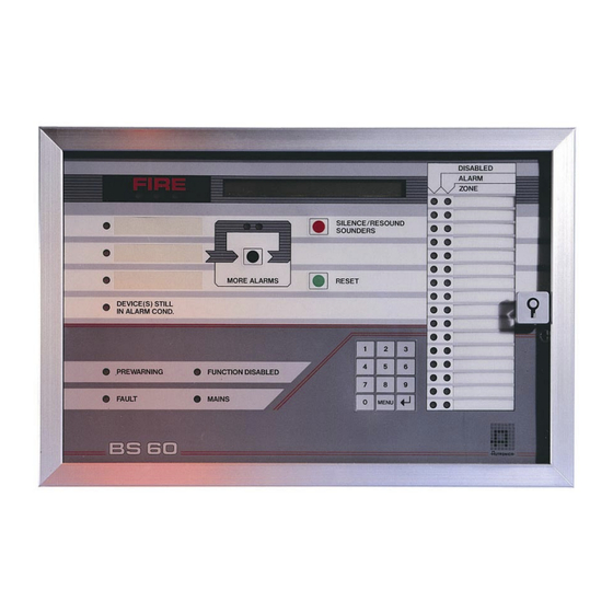
- Page 1 Fire Alarm Control Panel BS-60 Commissioning handbook Program version P1-BS60-202E-0 P-BS60/EEE/Doc/020402 Autronica Fire and Security AS...
-
Page 2: Table Of Contents
7. Texting the front of the Fire Alarm Control Panel ....18 Appendix A Paperstickers ..............19 Appendix B Table for System configuration data ......20 Appendix C Table for Operating, service and maintenance ...21 Appendix D BS-100 Master ............22 Appendix E Fault messages............26 P-BS60/EEE/Doc/020402 Autronica Fire and Security AS... -
Page 3: Intrduction
BS-60 Commissioning handbook 0. Introduction Introduction The program version P1-BS-60-201E-O is only to be implemented on BSA-60 board labeled 7212-197-0003. BSA-60 boards 7212-197-0001 and 7212-197-0002 has to be modified and labeled BS-991. “Updateing-kit” to BSA-60 has art.no. BST-10. 1. Pre-commissioning checks Checking 1.1 Recommended checking equipment... -
Page 4: Connections
Fig. no. 1 Rotating switch S17 DIP-switch S18 0,63A T 4A T 24V DC in 0,63A T 4A T Battery Fuses, sounders circuit: 0,63A T 1A T Output SSK 0,63A T Control 1 and 3 P-BS60/EEE/Doc/020402 Autronica Fire and Security AS... -
Page 5: Switch Setting
If the control panel is an independent unit the switch must be in the “0”-position. The switch is located under the S18 switch on the rear side of the front panel. See fig. 2. P-BS60/EEE/Doc/020402 Autronica Fire and Security AS... -
Page 6: Configuration
4. Configuration Configuration 4.1 Menu structure The whole menu structure is shown here, but only “CONFIGURATION”, and “SERVICE” is described in this handbook. For information about the other functions, see “Operators handbook” for BS-60. SELECT MAIN MENU 1-- Out/in- 1--Disable 1--Address... -
Page 7: Configuration Preaction
Select “CONFIGURATION” by pressing “3” in the “SYSTEM”-menu, and the following text will appear in the display: SYSTEM CONFIGURATION: 1:DATA 2:ZONE 3:AUTOMATIC 4:SAVE NB! Saving of configuration changes is password portected. See sec. 4.3.4. P-BS60/EEE/Doc/020402 Autronica Fire and Security AS... -
Page 8: Configuration - Data
Press ↵ ↵ ↵ ↵ and the following text will appear in the display: NUMBER OF CELLWARN: 00 Enter number of zone operating units (BK-50, if mounted) and press ↵ ↵ ↵ ↵ . P-BS60/EEE/Doc/020402 Autronica Fire and Security AS... - Page 9 This funciton has to be turned off when low-ohm sounders or sounders without a blocking diode (older installations) are connected. Select ON/OFF. Press ↵ ↵ ↵ ↵ , and the following text will appear in the display: SILENCE/RESOUND SOUNDER FUNCTION: 1 ON = 1, OFF = 0 P-BS60/EEE/Doc/020402 Autronica Fire and Security AS...
- Page 10 RESET FUNCTION: 1 ON = 1, OF =0 This function is used when the BS-60 control panel serves as a slave to a master. When selecting OFF, it will only be possible to reset the system from a master. If BS-60 is the main panel (independent), then select ON: Switch S18.3 OFF: Reset from both BS-100 and BS-60.
- Page 11 OFF - The external reset acts as a normal reset. Select ON/OFF. Press ↵ ↵ ↵ ↵ , and the system will return to the “SYSTEM CONFIGURATION”-menu. (Remember to save the configurated data before leaving the “SYSTEM CONFIGURATION”-menu. P-BS60/EEE/Doc/020402 Autronica Fire and Security AS...
-
Page 12: Configuration - Zone
Select “2” and enter the detector address to be deleted in the zone YYY. Press . The deleted address will appear in the second line. The system will propose to delete the following address. This address can be edited. P-BS60/EEE/Doc/020402 Autronica Fire and Security AS... - Page 13 Enter the zone to be renumbered, and press ↵ ↵ ↵ ↵ . SYSTEM CONFIG. ZONE RENUMBER FROM ZONE NO: YY1 TO ZONE NO: YY2 Enter the new zone number, and press ↵ ↵ ↵ ↵ . The “SYSTEM CONFIG. ZONE”-menu will appear in the display. P-BS60/EEE/Doc/020402 Autronica Fire and Security AS...
- Page 14 “SAVE” by pressing “4” in the “SYSTEM CONFIGURATION”-menu, and the following text will appear in the display: ENTER PASSWORD ***** (When configuraiton BS-60 the first time, the system demands that all configurations are confirmed before storing all activates. Verify or correct and press ↵ ↵ ↵ ↵ .
- Page 15 To activate the custom designed text/event log function, the following procedure must be carried out: • Power down the panel. • Set switch S18.7 in position “ON”. • Power up the panel. • Close the door. P-BS60/EEE/Doc/020402 Autronica Fire and Security AS...
-
Page 16: Service (Password Protected On Service Level)
Be sure that the detector/manual call point is defined in the selected zone to be tested. Write down the address of the detectors and manual call points which is tested. All detectors in the zone has to be tested before the test is ended. P-BS60/EEE/Doc/020402 Autronica Fire and Security AS... -
Page 17: Custom-Text
Press ↵ ↵ ↵ ↵ to reset number of restarts. Press “MENU” to return to the main menu. P-BS60/EEE/Doc/020402 Autronica Fire and Security AS... -
Page 18: Custom Design Text
The custom designed text must be entered from an IBM-compatible PC with serial and parallel output. To enter the text “Custom data tool for BS-60/BX-40”, art.no. P1-PCSYS-102 is required. The switch S18.7 has to be set in position “ON” when entering custom designed text. -
Page 19: Appendix A Paperstickers
BS-60 Commissioning handbook APPENDIX A Papertick no. 1 Paperstick no. 2 Paperstick no. 3 P-BS60/EEE/Doc/020402 Autronica Fire and Security AS... -
Page 20: Appendix B Table For System Configuration Data
ON=1, OFF=0 Prewarning output at control-2 ON=1, OFF=0 Battery voltage, 25,5 volts monitor ON=1, OFF=0 Door open, output at control-3 ON=1, OFF=0 Disablements, output at control-3 ON=1, OFF=0 Ext. silence sounder (ON)/reset (OFF) ON=1, OFF=0 P-BS60/EEE/Doc/020402 Autronica Fire and Security AS... -
Page 21: Appendix C Table For Operating, Service And Maintenance
LONG ON=1,OFF= Zone 1 Zone 2 Zone 3 Zone 4 Zone 5 Zone 6 Zone 7 Zone 8 Zone 9 Zone 10 Zone 11 Zone 12 Zone 13 Zone 14 Zone 15 Zone 16 P-BS60/EEE/Doc/020402 Autronica Fire and Security AS... -
Page 22: Appendix D Bs-100 Master
BS-60), the indication lamps on the panel front will light, the outputs will be activated etc. in a normal way. The custom texts presented in the display on both BS-100 and BS-60 has to be manually programmed in both control panels. - Page 23 There will be no display of info. on the BS-60 control panel(s). More alarms from a BS-60 control panel will also be registered as more alarms on the BS-100 control panel. There will be no display of info. on other BS-60 control panels.
- Page 24 It is advisable to disable / restore BS-60 addresses from the BS-100. D.3.1 Address The BS-100 can disable / restore all addresses in the system. The BS-60 can only disable / restore addresses connected at the relevant BS-60 control panel. D.3.2...
- Page 25 Sounders Sounders connected to the BS-100 control panel can only be disabled / restored from the BS-100 control panel. Sounders connected to a BS-60 control panel can only be disabled / restored at the relevant BS-60 control panel. D.3.5 Fire brigade / fighters BMA, BMF, BMFO outputs from the BS-100 control panel can only be disabled / restored from the BS-100 control panel.
- Page 28 For more than 40 years Autronica’s monitoring systems have been saving lives and preventing catastrophes on land and at sea. Autronica Fire and Security’s most important business area is fire detection & security. Autronica Fire and Security stands for protecting life, environment and property.
Need help?
Do you have a question about the BS-60 and is the answer not in the manual?
Questions and answers