
Related Manuals for Autronica BX-10


Summary of Contents for Autronica BX-10
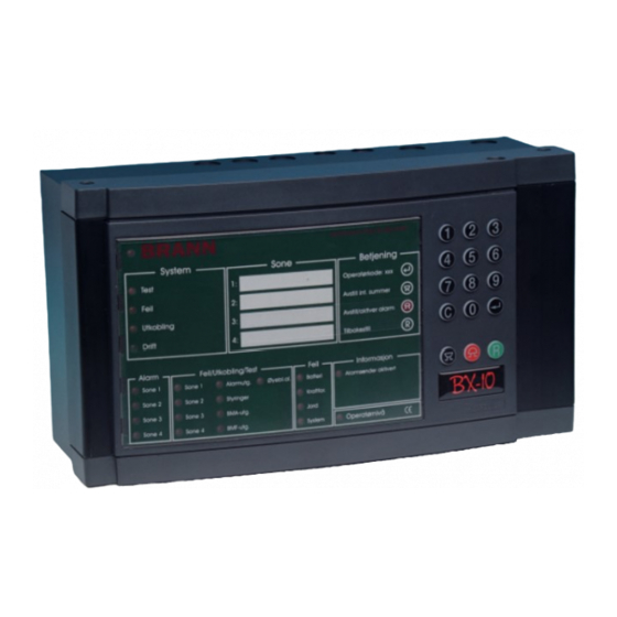
- Page 1 Fire Alarm Control panel BX-10 Conventional fire alarm control panel with 4 zones (loops) Operators Handbook Protecting life, environment and property... P-BX10/FE- Rev.F, 030123...
- Page 2 © COPYRIGHT This publication, or parts thereof, may not be reproduced in any form, by any method, for any purpose. Autronica Fire and Security AS and subsidiaries assume responsibility for any errors that may appear in the publication, or for damages arising from the information in it.
-
Page 3: Table Of Contents
Introduction ..................21 8.1.1 Maritime panel BX-10M ..........21 Activating from the front panel ............22 Testing indicator lights and internal buzzer ..25 Operators Handbook, Fire Alarm Control panel BX-10, P-BX10/FE - Rev.F, 030123, Autronica Fire and Security AS Page 1... - Page 4 System fault/controlled shut down of control panel... 29 10.1.12 Alarm sender activated..........29 10.1.13 Operator level/Service level ........29 10.2 BX-10 Control Panel variants ..........30 Reader’s Comments..........33 Operators Handbook, Fire Alarm Control panel BX-10, P-BX10/FE - Rev.F, 030123, Autronica Fire and Security AS Page 2...
-
Page 5: Introduction
In addition to this manual, the BX-10 control panel is covered by the following documents: Manual Item no. Installation Manual - BX-10 Fire Alarm Control Panel P-BX-10/IE Data sheet P-BX10/CE Operators Handbook, Fire Alarm Control panel BX-10, P-BX10/FE - Rev.F, 030123, Autronica Fire and Security AS Page 3... - Page 6 Introduction Operators Handbook, Fire Alarm Control panel BX-10, P-BX10/FE - Rev.F, 030123, Autronica Fire and Security AS Page 4...
-
Page 7: Operating The Control Panel
Operator code: 110 + Operators Handbook, Fire Alarm Control panel BX-10, P-BX10/FE - Rev.F, 030123, Autronica Fire and Security AS Page 5... -
Page 8: Keypad
Lamp test / audio warning device test 30 + ENTER (accept) (always accessible Resetting the keypad (always accessible * Maritime version has a 2 minutes delay. Operators Handbook, Fire Alarm Control panel BX-10, P-BX10/FE - Rev.F, 030123, Autronica Fire and Security AS Page 6... -
Page 9: Resetting The Keypad Using The C-Key
Battery Zone 2 Zone 2 Contr. Power. Zone 3 Zone 3 Al -outp. Earth Zone 4 Zone 4 Fault outp. Operator System Operators Handbook, Fire Alarm Control panel BX-10, P-BX10/FE - Rev.F, 030123, Autronica Fire and Security AS Page 7... - Page 10 Operating the control panel Operators Handbook, Fire Alarm Control panel BX-10, P-BX10/FE - Rev.F, 030123, Autronica Fire and Security AS Page 8...
-
Page 11: Led Indicators
Zone 2 BX-10 Zone 2 Contr. Power Zone 3 Zone 3 Al -outp. Earth Zone 4 Zone 4 Fault outp. Operator System Operators Handbook, Fire Alarm Control panel BX-10, P-BX10/FE - Rev.F, 030123, Autronica Fire and Security AS Page 9... - Page 12 LED indicators Operators Handbook, Fire Alarm Control panel BX-10, P-BX10/FE - Rev.F, 030123, Autronica Fire and Security AS Page 10...
-
Page 13: A Fire Alarm Is Activated
If a detector zone remains in alarm status after resetting the system, the alarm will be activated again. In such an instance the above steps must be repeated. Operators Handbook, Fire Alarm Control panel BX-10, P-BX10/FE - Rev.F, 030123, Autronica Fire and Security AS Page 11... - Page 14 LED indicators Operators Handbook, Fire Alarm Control panel BX-10, P-BX10/FE - Rev.F, 030123, Autronica Fire and Security AS Page 12...
-
Page 15: Fire Alarm With Delayed Warning
Note: The yellow DISABLING indicator and IMMEDIATE WARNING DISABLED indicator will remain on. Investigate the fire. (Continued on next page…..) Operators Handbook, Fire Alarm Control panel BX-10, P-BX10/FE - Rev.F, 030123, Autronica Fire and Security AS Page 13... - Page 16 If a detector zone remains in alarm status after resetting the system, the alarm will be activated again. In such an instance the above steps must be repeated. Operators Handbook, Fire Alarm Control panel BX-10, P-BX10/FE - Rev.F, 030123, Autronica Fire and Security AS Page 14...
-
Page 17: A Fault Arises
ON/1.5 sec. OFF) will change to the characteristics for fire (0.5 sec. ON/0.5 sec. OFF). When the alarm is rest (RESET ALARM), the visual characteristics for fault status will resume and the buzzer will switch off. Operators Handbook, Fire Alarm Control panel BX-10, P-BX10/FE - Rev.F, 030123, Autronica Fire and Security AS Page 15... - Page 18 Fire alarm with delayed warning Operators Handbook, Fire Alarm Control panel BX-10, P-BX10/FE - Rev.F, 030123, Autronica Fire and Security AS Page 16...
-
Page 19: Disabling/Restoring
* Disabled zones in the BX-10 system designed for agricultural use will be automatically restored after 4 hours. * Disables zones in the BX-10M (Maritime version) will not be restored automatically. Operators Handbook, Fire Alarm Control panel BX-10, P-BX10/FE - Rev.F, 030123, Autronica Fire and Security AS Page 17... -
Page 20: Disabling/Restoring From The Front Panel
24-hour time lapse. Disabling of immediate warning will be restored after 12 hours. * Agricultural version is automatically restored after 4 hours (special requirement). Operators Handbook, Fire Alarm Control panel BX-10, P-BX10/FE - Rev.F, 030123, Autronica Fire and Security AS Page 18... -
Page 21: Disabling/Restoring Of Zones From Auxiliary Switches
4 hours. Zone1 Zone 2 Zone 3 Zone 4 External auxiliary switch Operators Handbook, Fire Alarm Control panel BX-10, P-BX10/FE - Rev.F, 030123, Autronica Fire and Security AS Page 19... - Page 22 Disabling/restoring Operators Handbook, Fire Alarm Control panel BX-10, P-BX10/FE - Rev.F, 030123, Autronica Fire and Security AS Page 20...
-
Page 23: Activating The Alarm Delay Function
Continuous signal on panel buzzer. • Common alarm output (BMA) is not delayed. • No automatic restoring of the delay function after 12 hours. Operators Handbook, Fire Alarm Control panel BX-10, P-BX10/FE - Rev.F, 030123, Autronica Fire and Security AS Page 21... -
Page 24: Activating From The Front Panel
(after 12 hours) by the time- programmed safety restore function. *Maritime version; see appendix 10.2. Operators Handbook, Fire Alarm Control panel BX-10, P-BX10/FE - Rev.F, 030123, Autronica Fire and Security AS Page 22... - Page 25 New delay period is activated by cancelling and re-activating the auxiliary disabling switch. *Maritime version; see appendix 10.2. Operators Handbook, Fire Alarm Control panel BX-10, P-BX10/FE - Rev.F, 030123, Autronica Fire and Security AS Page 23...
- Page 26 Testing indicator lights and internal buzzer Operators Handbook, Fire Alarm Control panel BX-10, P-BX10/FE - Rev.F, 030123, Autronica Fire and Security AS Page 24...
-
Page 27: Testing Indicator Lights And Internal Buzzer
If an LED fails to light up, or the audio device is inaudible, contact the system administrator (or the technician responsible) immediately. Operators Handbook, Fire Alarm Control panel BX-10, P-BX10/FE - Rev.F, 030123, Autronica Fire and Security AS Page 25... - Page 28 Testing indicator lights and internal buzzer Operators Handbook, Fire Alarm Control panel BX-10, P-BX10/FE - Rev.F, 030123, Autronica Fire and Security AS Page 26...
-
Page 29: Appendix
Zone 4 with fault- remains disabled. active until control panel is reset. • Goes out when control panel is reset. Operators Handbook, Fire Alarm Control panel BX-10, P-BX10/FE - Rev.F, 030123, Autronica Fire and Security AS Page 27... -
Page 30: Fault/Disabling/Testing - Alarm Outputs
Yellow indicator is activated if a fault occurs. Activated if the control panel registers an operating voltage below 22.5V or above 30.0V Battery • Flashing yellow light with fault– remains until control panel is reset. Operators Handbook, Fire Alarm Control panel BX-10, P-BX10/FE - Rev.F, 030123, Autronica Fire and Security AS Page 28... -
Page 31: Fault On Power Supply/Charger Or Fuse (F8)
Constant yellow light remains as long as the control panel is in operator mode (5 minutes after the last key-stroke). Password (confidential information) 110 + Operator level: Operators Handbook, Fire Alarm Control panel BX-10, P-BX10/FE - Rev.F, 030123, Autronica Fire and Security AS Page 29... -
Page 32: Control Panel Variants
4. This enables intruder detectors on loop 4 to be disabled with the possibility for manual disabling/restoring via an external code switch on input 4. Operators Handbook, Fire Alarm Control panel BX-10, P-BX10/FE - Rev.F, 030123, Autronica Fire and Security AS Page 30... - Page 33 This is made possible by the external key switch giving 0 volts on input 5 on the terminal board. The key function will work parallel with operator code 110. Operators Handbook, Fire Alarm Control panel BX-10, P-BX10/FE - Rev.F, 030123, Autronica Fire and Security AS Page 31...
- Page 34 BX-10/NL: Dutch version (P1BX10-117-xx) This version has fixed alarm output signal on AK1 and AK2. Else like standard BX-10. Operators Handbook, Fire Alarm Control panel BX-10, P-BX10/FE - Rev.F, 030123, Autronica Fire and Security AS Page 32...
-
Page 35: Reader's Comments
Title: Operators Handbook, BX-10 Ref. No.: P-BX10/FE - Rev.F, 030123 Your information on any inaccuracies or omissions (with page reference): Please turn the page Operators Handbook,Fire Alarm Control panel BX-10, P-BX10/FE - Rev.F, 030123,, Autronica Fire and Security AS Page 33... - Page 36 Please send this form to: Autronica Fire and Security AS N-7483 Trondheim Norway Tel: + 47 73 58 25 00 Fax: + 47 73 58 25 01 Operators Handbook,Fire Alarm Control panel BX-10, P-BX10/FE - Rev.F, 030123,, Autronica Fire and Security AS Page 34...
- Page 37 Reader’s Comments Operators Handbook,Fire Alarm Control panel BX-10, P-BX10/FE - Rev.F, 030123,, Autronica Fire and Security AS Page 35...
- Page 39 Oil & Gas, Stavanger, Norway. Phone: + 47 51 84 09 00, fax: + 47 51 84 09 99. Autronica Industrial Ltd., Watford, United Kingdom. Phone: 1923 23 37 68, fax: 1923 22 55 77. Visit Autronica Fire and Security’s Web site:...
Need help?
Do you have a question about the BX-10 and is the answer not in the manual?
Questions and answers