
Related Manuals for NI DAQPad-MIO-16XE-50


Summary of Contents for NI DAQPad-MIO-16XE-50
- Page 1 DAQPad -MIO-16XE-50 User Manual 16-Bit Data Acquisition and Control for the Parallel Port DAQPad-MIO-16XE-50 User Manual June 2002 Edition Part Number 370511A-01...
- Page 2 Sweden 08 587 895 00, Switzerland 056 200 51 51, Taiwan 02 2528 7227, United Kingdom 01635 523545 For further support information, see the Technical Support and Professional Services appendix. To comment on the documentation, send email to techpubs@ni.com. © 2002 National Instruments Corporation. All rights reserved.
- Page 3 Warranty The DAQPad-MIO-16XE-50 is warranted against defects in materials and workmanship for a period of one year from the date of shipment, as evidenced by receipts or other documentation. National Instruments will, at its option, repair or replace equipment that proves to be defective during the warranty period.
- Page 4 Compliance FCC/Canada Radio Frequency Interference Compliance* Determining FCC Class The Federal Communications Commission (FCC) has rules to protect wireless communications from interference. The FCC places digital electronics into two classes. These classes are known as Class A (for use in industrial-commercial locations only) or Class B (for use in residential or commercial locations).
- Page 5 To obtain the DoC for this product, click Declaration of Conformity at . This Web site lists the DoCs ni.com/hardref.nsf/ by product family. Select the appropriate product family, followed by your product, and a link to the DoC appears in Adobe Acrobat format.
-
Page 6: Table Of Contents
BP-1 Battery Pack ...................1-4 Adding an Enhanced Parallel Port..............1-5 Parallel Port Cables ..................1-5 Unpacking ........................1-5 Safety Information ......................1-6 Chapter 2 Installing and Configuring the DAQPad-MIO-16XE-50 Installing the Software ....................2-1 Hardware Installation.....................2-2 Configuring the DAQPad-MIO-16XE-50 ..............2-4 Parallel Port .....................2-4 Analog Input....................2-4 Input Mode..................2-4... - Page 7 EXTSTROBE* Signal ..............3-33 Waveform Generation Timing Connections ........... 3-34 WFTRIG Signal................3-34 UPDATE* Signal ................3-35 UISOURCE Signal ................3-36 General-Purpose Timing Signal Connections..........3-37 GPCTR0_SOURCE Signal .............. 3-37 GPCTR0_GATE Signal ..............3-38 GPCTR0_OUT Signal ..............3-38 DAQPad-MIO-16XE-50 User Manual viii ni.com...
- Page 8 Chapter 4 Calibration Loading Calibration Constants ..................4-1 Self-Calibration......................4-2 External Calibration .......................4-2 Appendix A Specifications Appendix B Troubleshooting for Configuring Parallel Ports Appendix C Common Questions Appendix D Technical Support and Professional Services Glossary © National Instruments Corporation DAQPad-MIO-16XE-50 User Manual...
-
Page 9: About This Manual
About This Manual This manual describes the electrical and mechanical aspects of the DAQPad-MIO-16XE-50 and contains information concerning its operation and programming. The DAQPad-MIO-16XE-50 is a high-resolution, multifunction, portable data acquisition (DAQ) system that communicates with IBM PC/XT/AT and compatibles through the parallel port. The... -
Page 10: Ni Documentation
NI-DAQ NI-DAQ is used throughout this manual to refer to the NI-DAQ software for PC compatibles, unless otherwise noted. PC refers to the IBM PC/XT, the IBM PC AT, and compatible computers. -
Page 11: Introduction
Introduction This chapter describes the DAQPad-MIO-16XE-50, lists what you need to get started with the DAQPad-MIO-16XE-50, and describes the software programming choices and optional equipment. About the DAQPad-MIO-16XE-50 The DAQPad-MIO-16XE-50 is a high-resolution, multifunction, portable DAQ system that communicates through the parallel port on IBM PC/XT/AT and compatible computers. -
Page 12: What You Need To Get Started
Detailed specifications of the DAQPad-MIO-16XE-50 are in Appendix A, Specifications. What You Need to Get Started To set up and use the DAQPad-MIO-16XE-50, you need the following: ❑ DAQPad-MIO-16XE-50 ❑ DAQPad-MIO-16XE-50 User Manual ❑... -
Page 13: Software Programming Choices
DAQ Hardware Computer or Workstation Figure 1-1. The Relationship Among the Programming Environment, NI-DAQ, and the Hardware To download a free copy of the most recent version of NI-DAQ, click Download Software at ni.com © National Instruments Corporation DAQPad-MIO-16XE-50 User Manual... -
Page 14: National Instruments Ade Software
Using LabVIEW, Measurement Studio, or VI Logger greatly reduces the development time for your data acquisition and control application. Optional Equipment You can use the following NI products with the DAQPad-MIO-16XE-50: • BP-1 battery pack with a 110 or 230 VAC charger •... -
Page 15: Adding An Enhanced Parallel Port
You can use 36-pin MDR 1284-C male connectors as mating connectors for the DAQPad-MIO-16XE-50 rear connector, or you can use the NI adapter parallel port cable, which allows you to use a standard DB-25-style male connector as a mating connector. -
Page 16: Safety Information
Misuse of the product can result in a hazard. You can compromise the safety protection built into the product if the product is damaged in any way. If the product is damaged, return it to NI for repair. If the product is rated for use with hazardous voltages (>30 V , 42.4 V... - Page 17 MAINS is defined as the electricity supply system to which the equipment concerned is designed to be connected either for powering the equipment or for measurement purposes. © National Instruments Corporation DAQPad-MIO-16XE-50 User Manual...
- Page 18 Chapter 1 Introduction Below is a diagram of a sample installation DAQPad-MIO-16XE-50 User Manual ni.com...
-
Page 19: Installing And Configuring The Daqpad-Mio-16Xe-50
Install the application development environment (ADE), such as LabVIEW or Measurement Studio, according to the instructions on the CD and the release notes. Install NI-DAQ according to the instructions on the CD and the DAQ Quick Start Guide included with the device. Note It is important to install NI-DAQ before installing the DAQPad-MIO-16XE-50 to ensure that the device is properly detected. -
Page 20: Hardware Installation
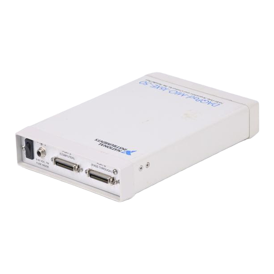
Chapter 2 Installing and Configuring the DAQPad-MIO-16XE-50 Hardware Installation There are five basic steps to installing the DAQPad-MIO-16XE-50. Refer to Figure 2-1 as you perform the following steps. DAQPad-MIO-16XE-50 DAQPad-TB-52 Front Panel Rear Panel Figure 2-1. Front and Rear View of a DAQPad-MIO-16XE-50... - Page 21 DAQPad-MIO-16XE-50 is protected by a positive temperature coefficient (PTC) resistor. It takes approximately 20 s for the PTC resistor to reset after being tripped. Contact NI if the power LED does not light up after correcting any faulty power connections.
-
Page 22: Configuring The Daqpad-Mio-16Xe-50
During configuration, you must know the parallel port I/O address and interrupt channel. Common parallel port I/O addresses are 0x378, 0x278, 0x3BC, 0x280 and 0x290. The DAQPad-MIO-16XE-50 can use the parallel port hardware interrupts for interrupt-driven data acquisition. Interrupt levels 7 and 5 are commonly used for parallel ports. Refer to the computer reference manual for details about interrupt selection and address assignment. -
Page 23: Input Polarity And Input Range
–V and +V . The DAQPad-MIO-16XE-50 has a unipolar input range of 10 V (0 to 10 V) and a bipolar input range of 20 V (±10 V). The software-programmable gain on this board increases its overall flexibility by matching the input signal ranges to those that the ADC can accommodate. -
Page 24: Considerations For Selecting Input Ranges
You can calibrate the AI circuitry for either a unipolar or bipolar polarity. If you mix Note unipolar and bipolar channels in the scan list and you are using NI-DAQ, NI-DAQ will load the calibration constants appropriate to the polarity for which analog input channel 0 is configured. - Page 25 Chapter 2 Installing and Configuring the DAQPad-MIO-16XE-50 reduces measurement noise, resulting in improved resolution. Dither, or additive white noise, has the effect of forcing quantization noise to become a zero-mean random variable rather than a deterministic function of the input signal.
-
Page 26: Multiple-Channel Scanning Considerations
Chapter 2 Installing and Configuring the DAQPad-MIO-16XE-50 You cannot disable dither on the DAQPad-MIO-16XE-50 because the resolution of the ADC is so fine that the ADC and the PGIA inherently produce almost 0.5 LSB of noise. This is equivalent to having a dither circuit that is always enabled. -
Page 27: Analog Output
Chapter 2 Installing and Configuring the DAQPad-MIO-16XE-50 Analog Output The DAQPad-MIO-16XE-50 supplies two channels of AO voltage on the DAQPad-TB-52. The range is fixed at bipolar ±10 V. Cold-Junction Sensing The DAQPad-MIO-16XE-50 includes a high accuracy thermistor temperature sensor for cold-junction compensation when you measure with thermocouples. -
Page 28: Digital I/O
T = thermistor temperature in Celsius, = thermistor temperature in Fahrenheit. Note For further information on using thermocouples, refer to NI Developer Zone tutorial, Measuring Temperature with Thermocouples, at ni.com/zone Digital I/O The DAQPad-MIO-16XE-50 contains eight lines of DIO for general-purpose use. - Page 29 Chapter 2 Installing and Configuring the DAQPad-MIO-16XE-50 PFI<0..9> CONVERT* Sample Interval Counter TC GPCTR0_OUT Figure 2-3. CONVERT* Signal Routing This figure shows that CONVERT* can be generated from a number of sources, including the external signals PFI<0..9> and the internal signals Sample Interval Counter TC and GPCTR0_OUT.
-
Page 30: Connecting The Signals
Connecting the Signals This chapter describes the connection of a standard parallel port device to the rear panel transparent parallel port connector and describes how to make signal connections to the DAQPad-MIO-16XE-50 using the DAQPad-TB-52. DAQPad-TB-52 Terminal Block The DAQPad-TB-52 is a detachable terminal block with 52 screw terminals designed to interface with the DAQPad-MIO-16XE-50. - Page 31 DAQPad-MIO-16XE-50 can damage the DAQPad-MIO-16XE-50 and the PC. Maximum input ratings for each signal are given in this chapter under the discussion of that signal. NI is not liable for any damage resulting from such signal connections. DAQPad-MIO-16XE-50 User Manual...
- Page 32 Analog Input Ground—These signals are the reference point for single-ended measurements and the bias current return point for differential measurements. All three ground references—AIGND, AOGND, and DGND—are connected together on the DAQPad-MIO-16XE-50. ACH<0..15> AIGND Input Analog Input Channels 0 through 15—Each channel pair, ACH<i, i+8>...
- Page 33 1 output. PFI5/UPDATE* DGND Input PFI5/Update—As an input, this is one of the PFIs. Output As an output, this is the UPDATE* signal. A high-to-low edge on UPDATE* indicates that the AO primary group is being updated. DAQPad-MIO-16XE-50 User Manual ni.com...
- Page 34 25/15 — — — ±3 nA in parallel with 100 pF AIGND — — — — — — 0.1 Ω DAC0OUT Short-circuit 5 at 10 5 at 10 2 V/µs — to ground © National Instruments Corporation DAQPad-MIO-16XE-50 User Manual...
- Page 35 PFI6/WFTRIG — +0.5 3.5 at 5 at 0.4 50 kΩ pu –0.4) PFI7/STARTSCAN — +0.5 3.5 at 5 at 0.4 50 kΩ pu –0.4) PFI8/GPCTR0_SOURCE — +0.5 3.5 at 5 at 0.4 50 kΩ pu –0.4) DAQPad-MIO-16XE-50 User Manual ni.com...
-
Page 36: Daqpad-Tb-52 Signal Connections
= pull up AO = Analog Output DO = Digital Output DAQPad-TB-52 Signal Connections You do not have to turn off the DAQPad-MIO-16XE-50 before removing the Note DAQPad-TB-52. To connect signals to the DAQPad-TB-52, perform the following steps: Disconnect and remove the DAQPad-TB-52 from the DAQPad-MIO-16XE-50 by unscrewing the front panel thumbscrews and then gently pulling on the front panel handle. -
Page 37: Analog Input Signal Connections
Caution Exceeding the maximum input voltage rating can damage the DAQPad-MIO-16XE-50 and the PC. NI is not liable for any damage resulting from such signal connections. In NRSE mode, the AISENSE signal is connected internally to the negative input of the DAQPad-MIO-16XE-50 PGIA. In DIFF and RSE modes, this signal is left unconnected. -
Page 38: Types Of Signal Sources
The PGIA applies gain and common-mode voltage rejection and presents high-input impedance to the AI signals connected to the DAQPad-MIO-16XE-50. Signals are routed to the positive and negative inputs of the PGIA through input multiplexers on the board. The PGIA converts two input signals to a signal that is the difference between the two input signals multiplied by the gain setting of the amplifier. -
Page 39: Floating Signal Sources
If you power both the DAQPad-MIO-16XE-50 and the PC with a floating power Note source (such as a battery) and you are not tying the DAQPad-TB-52 grounding lug to earth ground, the system is floating with respect to earth ground. - Page 40 Ground-loop losses, V , are added to measured signal. – AISENSE – AISENSE – – Single-Ended — Nonreferenced (NRSE) AIGND AIGND See text for information on bias resistors. Figure 3-3. Summary of AI Connections © National Instruments Corporation 3-11 DAQPad-MIO-16XE-50 User Manual...
-
Page 41: Differential Connection Considerations
Connecting the Signals Differential Connection Considerations A differential connection is one in which the DAQPad-MIO-16XE-50 AI signal has its own reference signal or signal return path. These connections are available when the selected channel is configured in DIFF input mode. -
Page 42: Differential Connections For Ground-Referenced Signal Sources
Chapter 3 Connecting the Signals Differential Connections for Ground-Referenced Signal Sources Figure 3-4 shows how to connect a ground-referenced signal source to a DAQPad-MIO-16XE-50 channel configured in DIFF input mode. ACH+ Programmable Ground- Gain Referenced Instrumentation Signal Amplifier Source –... -
Page 43: Differential Connections For Nonreferenced Or Floating Signal Sources
Chapter 3 Connecting the Signals Differential Connections for Nonreferenced or Floating Signal Sources Figure 3-5 shows how to connect a floating signal source to a DAQPad-MIO-16XE-50 channel configured in DIFF input mode. ACH+ Bias Resistors Programmable (see text) Gain Floating... - Page 44 Note These same issues regarding bias resistors also apply to a single-ended connection (NRSE configuration) for floating signal sources. © National Instruments Corporation 3-15 DAQPad-MIO-16XE-50 User Manual...
-
Page 45: Single-Ended Connection Considerations
• The input signal is high level (greater than 1 V). • The leads connecting the signal to the DAQPad-MIO-16XE-50 are less than 3 m (10 ft). • The input signal can share a common reference point with other signals. -
Page 46: Single-Ended Connections For Floating Signal Sources (Rse Configuration)
To measure a grounded signal source with a single-ended configuration, you must configure the DAQPad-MIO-16XE-50 for NRSE input. Connect the grounded signal to the positive input of the DAQPad-MIO-16XE-50 PGIA, and connect the signal local ground reference to the negative input of the DAQPad-MIO-16XE-50 PGIA. -
Page 47: Common-Mode Signal Rejection Considerations
Figures 3-4 and 3-7 show connections for signal sources that are already referenced to some ground point with respect to the DAQPad-MIO-16XE-50. In these cases, the PGIA can reject any voltage caused by ground potential differences between the signal source and the DAQPad-MIO-16XE-50. -
Page 48: External Current Excitation
100 µA of external excitation. Figure 3-8 suggests how you can connect several RTDs in series to the DAQPad-MIO-16XE-50 using four-wire measurement techniques. To connect the current excitation to IEX+ and IEX− terminals, push the slide switch labeled IEX to the ON position. - Page 49 AIGND. The voltage potential at IEX– varies between 1.7 and 0.1 V from 0 to 55 °C. You must take this voltage into account when realizing the common-mode signal rejection considerations discussed in the Common-Mode Signal Rejection Considerations section. DAQPad-MIO-16XE-50 User Manual 3-20 ni.com...
-
Page 50: Analog Output Signal Connections
AO channel 1. AOGND is the ground-reference signal for both AO channels and for the external reference signal. Figure 3-9 shows how to make AO connections and the external reference input connection to the DAQPad-MIO-16XE-50. DAC0OUT Channel 0 VOUT 0 Load –... -
Page 51: Digital I/O Signal Connections
TTL signals and sensing external device states such as the state of the switch in Figure 3-10. Digital output applications include sending TTL signals and driving external devices such as the LED shown in Figure 3-10. DAQPad-MIO-16XE-50 User Manual 3-22 ni.com... -
Page 52: Power Connections
Under no circumstances should you connect this +5 V power signal directly to Caution any other voltage source on the DAQPad-MIO-16XE-50 or any other device. Doing so can damage the DAQPad-MIO-16XE-50 and the PC. NI is not liable for damage resulting from such a connection. -
Page 53: Programmable Function Input Connections
13 timing signals, but using the edge or level detection depends upon the particular timing signal being controlled. The detection requirements for each timing signal are listed within the section that discusses that individual signal. DAQPad-MIO-16XE-50 User Manual 3-24 ni.com... -
Page 54: Daq Timing Connections
Figure 3-13 shows a typical pretriggered DAQ sequence. The description for each signal shown in these figures is included later in this chapter. TRIG1 STARTSCAN CONVERT* Scan Counter Figure 3-12. Typical Posttriggered Acquisition © National Instruments Corporation 3-25 DAQPad-MIO-16XE-50 User Manual... -
Page 55: Trig1 Signal
PFI. The output is an active high pulse with a pulse width of 50 to 100 ns. This output is set to high-impedance at start up. Figures 3-14 and 3-15 show the input and output timing requirements for the TRIG1 signal. DAQPad-MIO-16XE-50 User Manual 3-26 ni.com... -
Page 56: Trig2 Signal
After the selected edge of TRIG2 is received, the board acquires a fixed number of scans and the acquisition stops. This mode acquires data both before and after TRIG2 is received. © National Instruments Corporation 3-27 DAQPad-MIO-16XE-50 User Manual... -
Page 57: Startscan Signal
STARTSCAN is deasserted t after the last conversion in the scan is initiated. This output is set to high-impedance at start up. DAQPad-MIO-16XE-50 User Manual 3-28 ni.com... - Page 58 CONVERT* appears when the onboard sample interval counter reaches zero. If you select an external CONVERT*, the first external pulse after STARTSCAN generates a conversion. The STARTSCAN pulses should be separated by at least one scan period. © National Instruments Corporation 3-29 DAQPad-MIO-16XE-50 User Manual...
-
Page 59: Convert* Signal
Chapter 3 Connecting the Signals A counter on the DAQPad-MIO-16XE-50 internally generates the STARTSCAN signal unless you select some external source. This counter is started by the TRIG1 signal and is stopped either by software or the sample counter. Scans generated by either an internal or external STARTSCAN signal are inhibited unless they occur within a DAQ sequence. -
Page 60: Aigate Signal
Separate the CONVERT* pulses by at least one conversion period. The DAQPad-MIO-16XE-50 sample interval counter normally generates the CONVERT* signal unless you select some external source. The counter is started by the STARTSCAN signal and continues to count down and reload itself until the scan is finished. -
Page 61: Sisource Signal
Figure 3-21 shows the timing for the SCANCLK signal. In this figure, the falling edge of CONVERT* indicates the initiation of an A/D conversion. Note When using NI-DAQ, SCANCLK polarity is low-to-high and cannot be changed programmatically. DAQPad-MIO-16XE-50 User Manual 3-32 ni.com... -
Page 62: Extstrobe* Signal
Figure 3-22 shows the timing for the hardware-strobe mode EXTSTROBE* signal. = 600 ns or 5 s Figure 3-22. EXTSTROBE* Signal Timing Note EXTSTROBE cannot be enabled through NI-DAQ. © National Instruments Corporation 3-33 DAQPad-MIO-16XE-50 User Manual... -
Page 63: Waveform Generation Timing Connections
Chapter 3 Connecting the Signals Waveform Generation Timing Connections The analog group defined for the DAQPad-MIO-16XE-50 is controlled by WFTRIG, UPDATE*, and UISOURCE. WFTRIG Signal Any PFI signal can externally input WFTRIG, which is available as an output on the PFI6/WFTRIG screw terminal. -
Page 64: Update* Signal
Figure 3-26. UPDATE* Output Signal Timing The DACs are updated within 100 ns of the leading edge. Separate the UPDATE* pulses with enough time so that new data can be written to the DAC latches. © National Instruments Corporation 3-35 DAQPad-MIO-16XE-50 User Manual... -
Page 65: Uisource Signal
Chapter 3 Connecting the Signals The DAQPad-MIO-16XE-50 UI counter normally generates the UPDATE* signal unless you select some external source. The UI counter is started by the WFTRIG signal and can be stopped by software or the internal Buffer Counter. -
Page 66: General-Purpose Timing Signal Connections
The maximum allowed frequency is 20 MHz, with a minimum pulse width of 23 ns high or low. There is no minimum frequency limitation. The 20 MHz or 100 kHz timebase normally generates the GPCTR0_SOURCE signal unless you select some external source. © National Instruments Corporation 3-37 DAQPad-MIO-16XE-50 User Manual... -
Page 67: Gpctr0_Out Signal
TC and toggle output polarity on TC. The output polarity is software selectable for both options. This output is set to high-impedance at start up. Figure 3-30 shows the timing of the GPCTR0_OUT signal. DAQPad-MIO-16XE-50 User Manual 3-38 ni.com... -
Page 68: Gpctr0_Up_Down Signal
As an output, the GPCTR1_SOURCE monitors the actual clock connected to general-purpose counter 1, even if the source clock is being externally generated by another PFI. This output is set to high-impedance at start up. © National Instruments Corporation 3-39 DAQPad-MIO-16XE-50 User Manual... -
Page 69: Gpctr1_Gate Signal
As an output, the GPCTR1_GATE signal monitors the actual gate signal connected to general-purpose counter 1, even if the gate is being externally generated by another PFI. This output is set to high-impedance at start up. DAQPad-MIO-16XE-50 User Manual 3-40 ni.com... -
Page 70: Gpctr1_Out Signal
This input can be disabled so that software can control the up-down functionality and leave the DIO7 signal free for general use. © National Instruments Corporation 3-41 DAQPad-MIO-16XE-50 User Manual... - Page 71 The GATE input timing parameters are referenced to the signal at the SOURCE input or to one of the internally generated signals on the DAQPad-MIO-16XE-50. Figure 3-34 shows the GATE signal referenced to the rising edge of a source signal. The gate must be valid (either high or...
-
Page 72: Freq_Out Signal
Field Wiring Considerations Environmental noise can seriously affect the accuracy of measurements made with the DAQPad-MIO-16XE-50 if you do not take proper care when running signal wires between signal sources and the device. The following recommendations apply mainly to AI signal routing to the device, although they also apply to signal routing in general. - Page 73 Separate DAQPad-MIO-16XE-50 signal lines from high-current or high-voltage lines. These lines are capable of inducing currents in or voltages on the DAQPad-MIO-16XE-50 signal lines if they run in parallel paths at a close distance. To reduce the magnetic coupling between lines, separate them by a reasonable distance if they run in parallel, or run the lines at right angles to each other.
-
Page 74: Calibration
You cannot calibrate the constant current source used for cold-junction sensing and external current excitation. The constant current source is factory calibrated, and NI can recalibrate the unit if needed. To maintain the cold-junction sensor accuracy, NI recommends recalibrating the current source every year. -
Page 75: Self-Calibration
CalDACs with values either from the original factory calibration or from a calibration that you subsequently performed. The DAQPad-MIO-16XE-50 can measure and correct for almost all of its calibration-related errors without any external signal connections. The NI software provides a self-calibration method you can use. This self-calibration process, which takes only a few seconds, is the preferred method of assuring accuracy in your application. - Page 76 The reference should be several times more accurate than the device itself. For example, to calibrate a 16-bit device, the external reference should be at least ±0.001% (±10 ppm) accurate. To manually calibrate the DAQPad-MIO-16XE-50, refer to the E Series Calibration Procedure at ni.com/calibration ©...
-
Page 77: Appendix A Specifications
Specifications This appendix lists the DAQPad-MIO-16XE-50 specifications. These specifications are typical at 25 °C unless otherwise noted. Analog Input Input Characteristics Number of channels ....... 16 single-ended or 8 differential (software-selectable) Type of ADC.......... Successive approximation Resolution ..........16 bits, 1 in 65,536 Maximum sampling rate ...... - Page 78 Gain = 2, 10 ........±100 ppm of reading Gain = 100 ........±250 ppm of reading Amplifier Characteristics Input impedance Normal, powered on ......20 GΩ in parallel with 100 pF Powered off ........820 Ω min Overload ..........820 Ω min DAQPad-MIO-16XE-50 User Manual ni.com...
- Page 79 Gain = 1, 2, 10 ........ 0.5 LSB Gain = 100 ........0.8 LSB bipolar, 1.4 LSB unipolar Crosstalk (DC to 100 kHz) Adjacent channels ......–85 dB All other channels ......–100 dB © National Instruments Corporation DAQPad-MIO-16XE-50 User Manual...
- Page 80 Offset error After calibration.......±0.5 mV max Before calibration ......±85 mV max Gain error (relative to calibration reference) After calibration.......±0.01% of output max Before calibration ......±1% of output max Voltage Output Range ............±10 V Output coupling ........DC DAQPad-MIO-16XE-50 User Manual ni.com...
- Page 81 Channels..........1 Level............100 µA ±50 nA Max load resistance........ 80 kΩ Temperature coefficient ......±20 ppm/°C Long-term stability......... ±2,530 ppm/ 1,000 h Digital I/O Number of channels ....... 8 input/output Compatibility ......... TTL/CMOS © National Instruments Corporation DAQPad-MIO-16XE-50 User Manual...
- Page 82 Counter/timers .........20 MHz, 100 kHz Frequency scaler......10 MHz, 100 kHz Base clock accuracy........±0.01% Max source frequency......20 MHz Min source pulse duration ......10 ns, edge-detect mode Min gate pulse duration ......10 ns, edge-detect mode Data transfers ..........Interrupts, programmed I/O DAQPad-MIO-16XE-50 User Manual ni.com...
- Page 83 BP-1 battery pack......9 h Physical Dimensions..........3.8 by 14.6 by 21.3 cm (1.5 by 5.8 by 8.4 in.) Connector ..........Two 36-pin female MDR 1284-C rear connectors Weight ............ 0.8 kg (1.9 lb) © National Instruments Corporation DAQPad-MIO-16XE-50 User Manual...
- Page 84 Conformity (DoC) for this product for any additional regulatory compliance information. To obtain the DoC for this product, click Declaration of Conformity at . This Web site lists the DoCs by product family. Select the ni.com/hardref.nsf/ DAQPad-MIO-16XE-50 User Manual ni.com...
- Page 85 DC resistance of each cable wire less than 0.22 Ω/m • • Total propagation delay less than 150 ns Includes errors from analog input, excitation current source with one-year calibration, cold-junction sensor thermistor and thermal gradient over screw terminals. © National Instruments Corporation DAQPad-MIO-16XE-50 User Manual...
- Page 86 Troubleshooting for Configuring Parallel Ports This appendix contains parallel port configuration troubleshooting information. If you are using NI-DAQ for Windows, refer to for installation and troubleshooting instructions. ni.com/support/daq The configuration utility reports an error when I try to save the settings or test the device.
- Page 87 If either IRQ level 7 or level 5 is unselectable under the IRQ menu in Note WDAQCONF another NI device is using this interrupt. You must free the appropriate IRQ level to allocate it for your parallel port. You may have an interrupt conflict with a non-NI device. If you have installed a PCMCIA card or a plug-in board, you must ensure that neither IRQ5 nor IRQ7 has been allocated for these devices.
- Page 88 You may have to enable your parallel port as an EPP port. Check for configuration utilities and ensure that your port is configured for EPP. It is possible that the DAQPad-MIO-16XE-50 and NI-DAQ software are not compatible with your EPP port. In this case, your parallel port is treated as a Centronics port.
- Page 89 DAQPad-MIO-16XE-50. General Information How do I use the DAQPad-MIO-16XE-50 with the C API in NI-DAQ? The NI-DAQ User Manual for PC Compatibles contains example code and describes the general programming flow when using the NI-DAQ C API.
- Page 90 ACH1 and ACH2 to be RSE, Figure C-1 demonstrates how to program this configuration in LabVIEW. Figure C-1. Configuring Channels for Different Acquisition Modes in LabVIEW To enable multimode scanning in using NI-DAQ functions, call the function for each channel. AI_Configure I am seeing crosstalk or ghost voltages when sampling multiple channels.
- Page 91 I/O connector, route external signals to internal timing sources, or tie internal timing signals together. If you are using NI-DAQ with LabVIEW and you want to connect external signal sources to the PFI lines, you can use the AI Clock Config, AI Trigger ©...
- Page 92 If you enable a PFI line for output, do not connect any external signal sources to Caution it; if you do, you can damage the device, the computer, and the connected equipment. Table C-1 corresponds the hardware signal names to the software signal names in LabVIEW and NI-DAQ. Table C-1. Signal Name Equivalencies Hardware LabVIEW...
- Page 93 Appendix C Common Questions Installing and Configuring the Device Which NI document should I read first to get started using DAQ software? The DAQ Quick Start Guide and the NI-DAQ or ADE release notes documentation are good places to start.
- Page 94 • System Integration—If you have time constraints, limited in-house technical resources, or other project challenges, NI Alliance Program members can help. To learn more, call your local NI office or visit ni.com/alliance If you searched and could not find the answers you need, contact ni.com...
- Page 95 +5 volts signal amperes analog-to-digital alternating current ACH <0..7> Analog Channel 0 through 7 signals analog-to-digital converter AIGATE analog input gate signal AIGND analog input ground signal AISENSE analog input sense signal © National Instruments Corporation DAQPad-MIO-16XE-50 User Manual...
- Page 96 CONVERT* convert signal digital-to-analog digital-to-analog converter data acquisition DAC0OUT, voltage output signals for channels 0 and 1 DAC1OUT decibels direct current DIFF differential Deutsche Industrie Norme DIO<0..7> digital I/O signals direct memory access DAQPad-MIO-16XE-50 User Manual ni.com...
- Page 97 0 output signal GPCTR0_SOURCE counter 0 source signal GPCTR0_UP_DOWN counter 1 up/down signal GPCTR1 GATE counter 1 gate signal GPCTR1_OUT counter 1 output signal GPCTR1_SOURCE counter 1 source signal GPCTR1_UP_DOWN counter 1 up/down signal hexadecimal © National Instruments Corporation DAQPad-MIO-16XE-50 User Manual...
- Page 98 PGIA is allowed to settle before the next channel is sampled. The interchannel delay is regulated by CONVERT*. light-emitting diode least significant bit meters maximum megabytes of memory minimum multifunction I/O most significant bit NRSE nonreferenced single-ended DAQPad-MIO-16XE-50 User Manual ni.com...
- Page 99 STARTSCAN scan rate reciprocal of the scan interval SCANCLK scan clock signal SCXI Signal Conditioning eXtensions for Instrumentation (bus) STARTSCAN start of scan signal thermistor temperature in Celsius thermistor temperature in Fahrenheit © National Instruments Corporation DAQPad-MIO-16XE-50 User Manual...
- Page 100 1 update interval source signal UPDATE* update signal volts common-mode noise differential input voltage diff external voltage virtual instrument ± positive/negative input voltage measured voltage volts, root-mean-square signal source temperature sensor in volts temp sensor watts WFTRIG waveform trigger signal DAQPad-MIO-16XE-50 User Manual ni.com...
Need help?
Do you have a question about the DAQPad-MIO-16XE-50 and is the answer not in the manual?
Questions and answers