
Subscribe to Our Youtube Channel
Related Manuals for NI 9476


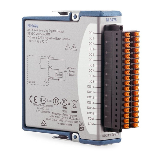
Summary of Contents for NI 9476
- Page 1 GETTING STARTED GUIDE NI 9476 36 V, 32-Channel (Sourcing Output), 500 µs C Series Digital Module...
-
Page 2: Safety Guidelines
This document explains how to connect to the NI 9476. In this document, the NI 9476 with spring terminal and the NI 9476 with DSUB are referred to inclusively as the NI 9476. Before you begin, complete the software and... -
Page 3: Safety Guidelines For Hazardous Voltages
All wiring must be insulated for the highest Caution voltage used. Do not mix hazardous voltage circuits and Caution human-accessible circuits on the same module. NI 9476 Getting Started Guide | © National Instruments | 3... - Page 4 ≤ V ≤ V Isolation Channel-to-channel None Channel-to-earth ground Continuous 250 V RMS, Measurement Category II Withstand up to 3,000 V RMS, verified by a 5 s 5,000 m dielectric withstand test 4 | ni.com | NI 9476 Getting Started Guide...
- Page 5 Measurement Categories III or IV. NI 9476 with DSUB Safety Voltages Connect only voltages that are within the following limits. -to-COM 40 V DC maximum ≤ V ≤ V Isolation Channel-to-channel None NI 9476 Getting Started Guide | © National Instruments | 5...
- Page 6 Such voltage measurements include signal levels, special equipment, limited-energy parts of equipment, circuits powered by regulated low-voltage sources, and electronics. Do not connect the NI 9476 with DSUB to Caution signals or use for measurements within Measurement Categories II, III, or IV.
-
Page 7: Safety Guidelines For Hazardous Locations
Categories CAT II, CAT III, or CAT IV. Safety Guidelines for Hazardous Locations The NI 9476 is suitable for use in Class I, Division 2, Groups A, B, C, D, T4 hazardous locations; Class I, Zone 2, AEx nA IIC T4 Gc and Ex nA IIC T4 Gc hazardous locations;... - Page 8 II 3G and is suitable for use in Zone 2 hazardous locations, in ambient temperatures of -40 °C ≤ Ta ≤ 70 °C. If you are using the NI 9476 in Gas Group IIC hazardous locations, you must use the device in an NI chassis that has been evaluated as Ex nC IIC T4, Ex IIC T4, Ex nA IIC T4, or Ex nL IIC T4 equipment.
-
Page 9: Electromagnetic Compatibility Guidelines
This product is intended for use in industrial locations. However, harmful interference may occur in some installations, when the product is connected to a peripheral device or test object, or if the NI 9476 Getting Started Guide | © National Instruments | 9... -
Page 10: Special Conditions For Marine Applications
In addition, take precautions when designing, selecting, and installing measurement probes and cables to ensure that the desired EMC performance is attained. 10 | ni.com | NI 9476 Getting Started Guide... -
Page 11: Preparing The Environment
Preparing the Environment Ensure that the environment in which you are using the NI 9476 meets the following specifications. Operating temperature -40 °C to 70 °C (IEC 60068-2-1, IEC 60068-2-2) Operating humidity 10% RH to 90% RH, (IEC 60068-2-78) noncondensing... - Page 12 Vsup DO25 Vsup DO24 DO10 DO26 DO25 DO27 DO11 DO10 DO26 DO12 DO28 DO11 DO27 DO12 DO13 DO29 DO28 DO13 DO30 DO14 DO29 DO14 DO30 DO15 DO31 DO15 DO31 Vsup Vsup 12 | ni.com | NI 9476 Getting Started Guide...
-
Page 13: Connecting A Device
Common reference connection Digital output signal connection Voltage supply input connection Connecting a Device Connect the device to DO and COM, and connect the external power supply to V and COM. NI 9476 Getting Started Guide | © National Instruments | 13... -
Page 14: Connecting An External Power Supply
Connecting an External Power Supply You must connect an external power supply with a 6 V DC to 36 V DC voltage range to the NI 9476. This power supply provides the current for the devices you connect to the module. -
Page 15: Connection Guidelines
NI 9476. • For the NI 9476 with spring terminal, push the wire into the terminal when using a solid wire or a stranded wire with a ferrule. -
Page 16: Overvoltage Protection
The NI 9476 is protected against overcurrent, inrush, and short- circuit conditions in accordance with IEC 61131-2. Each channel on the NI 9476 has circuitry that protects it from voltage and current surges resulting from short circuits. The NI 9476 can be damaged under Caution overvoltage and reverse bias voltage conditions. - Page 17 Protecting the Module from Flyback Voltages Install an external flyback diode if the NI 9476 is switching an inductive or energy-storing device such as a solenoid, motor, or relay, and the device does not have flyback protection.
- Page 18 1 A of current, connect DO<0..3> in parallel. You must turn all parallel channels on and off simultaneously so that the current on any single channel cannot exceed the 250 mA rating. 18 | ni.com | NI 9476 Getting Started Guide...
- Page 19 250 mA External Power 250 mA Supply Device 250 mA 250 mA NI 9476 NI 9476 Getting Started Guide | © National Instruments | 19...
-
Page 20: Where To Go Next
NI 9476 Datasheet NI 9476 Datasheet NI-RIO Help NI-DAQmx Help LabVIEW FPGA Help LabVIEW Help RELATED INFORMATION C Series Documentation Services & Resources ni.com/services ni.com/info cseriesdoc Located at ni.com/manuals Installs with the software 20 | ni.com | NI 9476 Getting Started Guide... -
Page 21: Worldwide Support And Services
You can obtain the DoC for your product by visiting ni.com/certification. If your product supports calibration, you can obtain the calibration certificate for your product at ni.com/calibration. NI 9476 Getting Started Guide | © National Instruments | 21... - Page 22 . You can find information about end-user license agreements (EULAs) and third-party patents legal notices in the readme file for your NI product. Refer to the Export Compliance Information at for the NI global trade compliance policy and how to obtain ni.com/legal/export-compliance...
Need help?
Do you have a question about the 9476 and is the answer not in the manual?
Questions and answers