Table of Contents
Advertisement
Quick Links
Advertisement
Table of Contents

Related Manuals for ISA ISETTA 4 LX


Summary of Contents for ISA ISETTA 4 LX
- Page 1 RS TB TP RS TB TP RS TB TP RS TB TP RS TB TP RS TB TP ISA S.r.l. Via del Lavoro, 5 06083 Bastia Umbra - Perugia - Italy Tel. +39 075 80171 - Fax +39 075 8000900 www.isaitaly.com ISETTA...
-
Page 2: Table Of Contents
1. NOTES / IMPORTANT NOTES ........4 1.1 Introduction ..........5 1.2 Manufacturer's contact details . - Page 3 The manual contains symbols to attract the reader's attention and highlight particularly important aspects. The table below illustrates the meaning of the various symbols used. Read the instruction manual Wear protective clothing Danger: Electrical parts under voltage Required maintenance or operations that must be performed by qualifi...
-
Page 4: Notes / Important Notes
1. NOTES / IMPORTANT NOTES The content of this manual is of technical nature and is owned by ISA S.r.l. It is forbidden to reproduce, circulate or modify all or part of its content without written consent. Any infringement will be legally pursued. -
Page 5: Introduction
1.1 Introduction ISA S.r.l. employs materials of the best quality and as they enter the company, we constantly monitor their storage and the use as part of the manufacturing process to prevent damage, deterioration and failure. All manufacturing elements are designed and manufactured in order to guarantee reliability and high safety standards. -
Page 6: Safety
2. SAFETY The buyer is responsible for training personnel using the appliance on the risks, safety devices and general health and safety rules required by the laws of the country where the equipment is installed. Users/operators should be aware of the position of all the controls and how they work, as well as of the features of the equipment. -
Page 7: Disconnecting Electrical Power Supply
2.2.3 Disconnecting electrical power supply Before conducting any maintenance works on the equipment or part of it, it is necessary to section the power supply that powers it Danger We therefore remind you, if maintenance is carried out and the operator cannot prevent bystanders from accidentally closing the circuit, to fully disconnect the equipment from the electric network. -
Page 8: Explosions
2.3.3 Explosions The equipment must not be located in an area classifi ed as an explosion risk according to 1999/92/EC, such as: Zone 0 An area in which there is a permanent, long-lasting or frequently explosive atmosphere made up of a mixture of air and fl ammable substances in the form of gases, fumes or steam. -
Page 9: Refrigerant R290
2.5 Refrigerant R290 This equipment contains a small amount of R290 refrigerant, an environmentally compatible gas, but one that is highly fl ammable. Be very carefully during transport, installation of the equipment and disposal to not damage the refrigerant circuit pipes. Maintenance must be performed by qualifi... -
Page 10: Disposing Of Exhaust Materials
3. DISPOSING OF EXHAUST MATERIALS During normal operation, the equipment does not generate any environmental contamination. At the end of its life cycle, or if it is necessary to proceed to permanent decommissioning, we recommend following the procedures below: DISPOSAL (User) The symbol, applied to either the product or its packaging, indicates that the product should not be considered as normal domestic waste, but should be taken to a waste collection point for the recycling of electrical and electronic appliances. -
Page 11: Installation
4. INSTALLATION This manual provides information on how to correctly unpack the equipment, the procedures to position it and describes how to connect the equipment to the electric network. 4.1 Storage and unpacking The equipment, with or without the packaging, should be carefully stored inside warehouses or in areas away from the elements and direct sunlight, at a temperature between 0 and +40 °C. -
Page 12: Technical Specifications
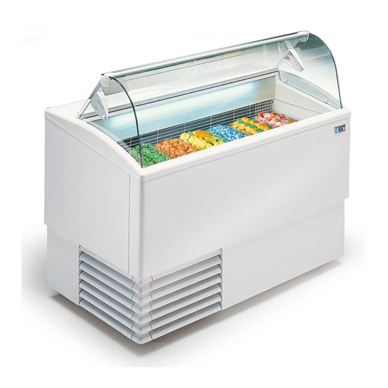
5. TECHNICAL SPECIFICATIONS This refrigerated cabinet is exclusively intended to display and sell of gelato. The manufacturer is not liable for injury to persons or damage to property or the equipment itself caused by the displaying of products other than those described above. Improper use: - Food preservation. - Page 13 5. TECHNICAL SPECIFICATIONS TECHNICAL FEATURES R404A RS TB TP RS TB TP RS TB TP RS TB TP RS TB TP External dimensions (lxpxh) 824 x 760 x 1176 1184 x 800 x 1176 1354 x 800 x 1176 1659 x 800 x 1176 2119 x 800 x 1176 Refrigeration Static...
-
Page 14: Installation
5.1 Installation Attention It is essential that you follow the distances indicated (mm) in order to correctly install the equipment. aaaaaaaaaaaaaaaaaaaaaaaaaaaaaaa aaaaaaaaaaaaaaaaaa aaaaaaaaaaaaaaaaaaaaaaaaaaaaaaa aaaaaaaaaaaaaaaaaa aaaaaaaaaaaaaaaaaaaaaaaaaaaaaaaaaaaaaaaaaaaaaaaaaaa aaaaaaaaaaaaaaaaaaaaaaaaaaaaaaaaaaaaaaaaaaaaaaaaaaa 5.2 Positioning Warning The cabinet is equipped with pivoting whells for an easier handling. It ‘s absolutely necessary to stabilize after placement the equipment to the fl... -
Page 15: Equipment Description
6. EQUIPMENT DESCRIPTION 6.1 Assembled structure The equipment comprises a single furniture on which all the functional devices needed to make it a professional product effi cient for its intended use are assembled. The equipment comprises: - Insulated structure in ecological polyurethane - Cooling system - Electronic control panel - Electrical system... -
Page 16: Optional Features
7. CONTROL PANEL The control panel is made up from the following components: Electronic control board Cabinet switch Light switch Storage thermostat Storage switch 7.1 Start-up Activate the mains system master switch. Plug the refrigerated cabinet in at the socket supplied by the customer, ensuring that the plug is fi... -
Page 17: User Interface Eliwell Ew974
7.2 User Interface EW974 - EW978 Attention The electronic control board should be installed using the default settings. Any changes to the control board settings can be carried out exclusively by qualifi ed personnel. When started, the instrument runs a LAMP TEST for a few seconds. -
Page 18: User Interface Dixell Xr44Cx
SET Button Press the SET (ENTER) button and release immediately. The label “Set” will appear. To view the Setpoint value, press the SET (ENTER) again. The Setpoint value will appear on the display. To change the Setpoint value, press the UP and DOWN buttons within 15 seconds. To confi... - Page 19 KEYS - Combined pressure To lock and unlock the keyboard. To enter programming. To exit the programming. Mode Signifi cation Compressor/s on Blinking Anti-short cycle time delay Defrost in progress Blinking Drip in progress Temperature alarm Continuous cycle in progress Enery saving in progress Unit of measure Blinking...
-
Page 20: Routine Maintenance And Regular Checks
8. ROUTINE MAINTENANCE and REGULAR CHECKS 8.1 Cleaning inside the cabinet a) Remove pans of ice cream relocate immediately to a special freezer to ensure the proper storage of the product. b) Switch the appliance off (as applicable). Wait at least 4 to 6 hours, until the ice on the evaporator has melted completely, before proceeding with cleaning operations. -
Page 21: Access Condensing Unit
8.2 Access condensing unit BACK a) Remove the fi xing screws of the protective grille. b) Remove the protective grille. 8.3 Cleaning condensing unit FRONT a) Remove the fi xing screws of the protective carter. b) Remove the protective carter. Attention Clean the condensing unit with a vacuum brush. -
Page 22: Maintenance
9. MAINTENANCE Any work conducted on the equipment MUST involve disconnection from the power socket and in any case, none of the protective elements (grid, casing) should be removed by non-qualifi ed staff. The equipment must absolutely not be operated when these protective elements have been removed. The person responsible for the equipment is required to have maintenance performed on the equipment according to the frequency indicated in the table below, contacting the authorised Technical Assistance when necessary. -
Page 23: Technical Assistance
Replace the electronic control board. The electronic control board, if designed for R290 refrigerant must be replaced only with an origi- nal provided by ISA. Replace the temperature probes only after checking which of the two is not operating effi ciently. -
Page 24: List Of Alarms On The Electronic Controller
10.2 List of alarms on electronic controller (if included) ALARM DESCRIPTION SOLUTIONS Broken thermostat probe. Contact Technical Assistance. The alarm starts a few seconds after the probe breaks Compressor trip with “CON” and down; it stops a few seconds after the probe starts “COF"... -
Page 25: Annexes
12. ANNEXES N° Code Model Page Wiring diagram 412100109400 4 RS TB TP 6R RS TB TP 7R RS TB TP 9R RS TB TP Wiring diagram 412119182400 12R RS TB TP Wiring diagram 412100253000 6R RS TB TP Wiring diagram 412100258000 4 RS TB TP 7R RS TB TP... - Page 26 Annex 1 R404A Model 4 RS TB TP Model 6R RS TB TP Model 7R RS TB TP Model 9R RS TB TP Code 412100109400 Electronic control board Switch cabinet Lighting switch Klixon of end defrosting Safety Klixon Reactor Fluorescent tube T8 Heating elements defrost Heating element worktop Temperature probe...
- Page 27 Annex 2 R404A Model 12R RS TB TP Code 412119182400 Electronic control board Switch cabinet Lighting switch Storage switch Klixon of end defrosting Safety Klixon Reactor Fluorescent tube T8 Heating elements defrost Heating element worktop Temperature probe Defrosting probe Compressor Condenser ventilator Cleaning ventilator Storage compressor...
- Page 28 Annex 3 R404A Model 6R RS TB TP Code 412100253000 Electronic control board Power supply LED Switch cabinet Lighting switch Heating elements defrost Heating element worktop Temperature probe Defrosting probe Compressor Condenser ventilator Cleaning ventilator Power Cable ISETTA USE AND MAINTENANCE MANUAL 428000372237...
- Page 29 Annex 4 R290 Model 4 RS TB TP Model 7R RS TB TP Code 412100258000 Electronic control board Power supply LED Klixon of end defrosting Safety Klixon Heating elements defrost Heating element worktop Temperature probe Defrosting probe Compressor Condenser ventilator Cleaning ventilator Power Cable ISETTA...
- Page 30 Annex 5 R290 Model 4 RS TB TP Model 7R RS TB TP Code 412100308000 Electronic control board Power supply LED Klixon of end defrosting Safety Klixon Heating elements defrost Heating element worktop Temperature probe Defrosting probe Trasformer Compressor Condenser ventilator Cleaning ventilator Power Cable ISETTA...
- Page 31 Annex 6 DECLARATION OF CONFORMITY We: ISA S.r.l. Via del Lavoro, 5 - 06083 - Bastia Umbra (PG) declare under our own responsibility, that the product: ISETTA Product: Serial number: ..To which this declaration refers, is in compliance with e following: MACHINERY SAFETY General electric safety Standard EN 60335-1/Ed.2002+Modifi...
Need help?
Do you have a question about the ISETTA 4 LX and is the answer not in the manual?
Questions and answers