Table of Contents
Advertisement
Advertisement
Table of Contents

Related Manuals for Merits Silverado Extreme S940A Series


Summary of Contents for Merits Silverado Extreme S940A Series
- Page 1 S940A series Service Manual Oct.05.2015 V0...
-
Page 2: Table Of Contents
Index 1. Introduction ..................P1 2. Service Guide .................. P1 2.1. How to replace or repair the seat assembly ..........2.1.1. To remove seat body assembly ................... P1 2.1.2. To replace the seat base plate ..................P1 2.1.3. To replace the slide ...................... P2 2.1.4. - Page 3 2.5.3. To replace the indicator light set ................. P16 2.5.4. To replace the handle bar set ..................P17 2.5.5. To replace the rear-view mirror ................... P17 2.5.6. To replace the adjustable mechanical lock ..............P17 2.5.7. To replace the PCB modular ..................P17 2.5.8.
-
Page 4: Introduction
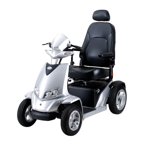
1. Introduction The purpose of this manual is to provide dealers and/or distributors with the product information and instructions that are required for servicing the S940A scooter. 2. Service Guide S940A scooter consists of four main parts: Seat Assembly ... -
Page 5: To Replace The Slide
Use ratchet & socket to loosen four screws (3.15) from the bottom of the seat body assembly, then remove the seat base plate. [see Illus. 02] Illus. 02 2.1.3. To replace the slide ◆ When you should replace the slide? ◇... -
Page 6: To Replace The Arm Pad
Illus. 03 Illus. 04 2.1.5. To replace the arm pad ◆ When you should replace the arm pad? ◇ If the arm pad is worn out. ◇ If the arm pad is pierced or scratched by something. ◇ If the scooter crashed cause the arm pad out of shape. ◆... -
Page 7: To Replace The Seat Post
Revolve the knob (3.08) and pull the armrest assembly outside [see Illus. 02]. If the arm pad (3.28) is broken, use the screwdriver to loosen two screws (3.30) and replace it. [see Illus. 05] Illus. 05 2.1.6. To replace the seat post [see Illus. -
Page 8: How To Replace Or Repair The Batteries
Use two open-end wrenches to loosen hexagon fixed bolt (1.77) screw (1.75), washer (1.76). Adjust the seat height based (1.78) to the demanded position (there are 5 holes on the tube for adjusting the seat height). Then insert and tighten the bolt. 2.2. -
Page 9: How To Replace Or Repair The Rear Section Assembly
3. Remove the batteries (9.1) from the front frame (1.01). 4. Use the screwdriver to loosen battery’s screws and nuts with battery harness (8.1). 5. To replace the new batteries (9.1), then reverse the 4~1 step to reinstall the scooter. 2.3. -
Page 10: To Replace The Suspension
Illus. 09 2.3.1. To replace the fender and the motor shroud [see Illus. 09] ◆ When you should replace the fender and the motor shroud? ◇ If your scooter can not avoid knocked or bumped cause the shroud broken. ◆ How to replace the fender and the motor shroud shroud? ◇... -
Page 11: To Replace The Transaxle Assembly
◆ How to replace the transaxle assembly? ◇ Please proceeding steps as follows if it has to replace. 1. Use the hex. tools to loosen two screws (3.05), nuts (3.06). 2. Remove the suspensions (3.04) and replace the new one. 2.3.3. -
Page 12: To Replace The Rear Tire
Illus. 17 Illus. 10 2.3.5. To replace the rear tire [see Illus. 10] 1. Release the air from valve of inner tire (4.75). 2. Use the wrench to loosen three screws (4.76) and nuts (4.77). 3. Disassemble the outer rear rime (4.72), inner rear rime (4.71). 4. -
Page 13: To Replace The Front Bumper
2.4. How to replace or repair the ront section assembly The front section assembly includes front frame, front shroud, controller front wheel assembly, carpet, front / rear bumper, steering mechanism, rear anti-tip assembly. Let the user comfortable drive. Note : The step of separate. [see Illus. -
Page 14: To Replace The Front Shroud
Illus. 12 2.4.2. To replace the front shroud [see Illus. 12] ◆ When you should replace the front shroud? ◇ If your scooter can not avoid knocked or bumped cause the shroud broken. ◆ How to replace the front shroud?\ ◇... -
Page 15: To Replace The Front Windshield Shroud
2. Replace the new front shroud and reverse disassembly step. 2.4.3. To replace the front windshield shroud [see Illus. 13] ◆ When you should replace the front windshield shroud? ◇ If your scooter can not avoid knocked or bumped cause the shroud broken. -
Page 16: To Replace The Front Tire
◆ How to replace the front wheel assembly? ◇ Please proceeding steps as follows if it has to replace. 1. Use the clamp to remove the screw covers (2.53). 2. Use the hex. tools to loosen the nuts from the arm spindle assembly. Then remove the front wheel assembly (2.5). -
Page 17: To Replace The Steering Mechanism
2.4.7. To replace the steering mechanism [see Illus. 12] ◆ When should you replace the steering mechanism? ◇ If the steering mechanism out of shape due to an accident. ◇ If the steering mechanism is deformation. ◇ If the steering mechanism has noise. ◇... -
Page 18: To Remove The Front & Rear Shroud Assembly
2.5.2. To remove the front & rear shroud assembly [see Illus. 15,16] ◆ When you should remove the front & rear shroud assembly? ◇ If your front & rear shroud assembly is deformation. ◇ If the front & rear shroud assembly out of shape due to an accident. ◇... -
Page 19: To Replace The Indicator Light Set
Illus. 16 1. Use the screwdriver to loosen screws (6.54, 6.68, 6.69, 6.78). Then take off the rear shroud assembly (6.8), front shroud assembly (6.5), the dash board assembly (5.5). 2. Unplug the indicator light set (6.51, 6.52) of the cable loom (5.30). 2.5.3. -
Page 20: To Replace The Handle Bar Set
1.Use the hex. tools to loosen two screws (6.53) from the front shroud. 2. Remove the indicator light set (6.51, 6.52) and replace new one. 2.5.4. To replace the handle bar set [see Illus. 15] ◆ When you should replace the handle bar set? ◇... -
Page 21: To Replace The Key And Key Switch
1. Disconnect all harness (5.17, 5.25, 5.26, 5.29, 5.31, 5.56) connected with in PCB modular (5.58). 2. Use the hex. tools to loosen four screws (5.59) from dash board (5.50). 3. Remove the PCB modular from and replace new one. 2.5.8. - Page 22 ◇ If the potentiometer no function with throttle lever. ◆ How to replace the potentiometer? ◇ Please proceeding steps as follows if it has to replace. 1. Unplug the speed pot wire (5.17) of the PCB modular. 2.Use the hex. tools to loosen two screws (5.19) from the upper tiller (5.01).
Need help?
Do you have a question about the Silverado Extreme S940A Series and is the answer not in the manual?
Questions and answers