Sign In
Upload
Manuals
Brands
Unipower Manuals
Battery Charger
ARR-M Series
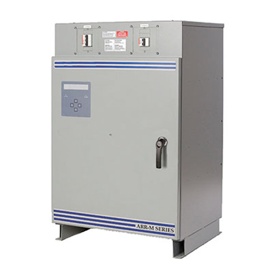
Unipower ARR-M Series Utility Charger Manuals
Manuals and User Guides for Unipower ARR-M Series Utility Charger. We have
1
Unipower ARR-M Series Utility Charger manual available for free PDF download: Product Manual
Unipower ARR-M Series Product Manual (136 pages)
Brand:
Unipower
| Category:
Battery Charger
| Size: 1 MB
Table of Contents
Battery Charger User's Manual
3
Table of Contents
3
Part - 1 : Installation
6
Introduction
7
Important Safety Instructions
7
Storage / Maintenance During Storage
7
Placement and Installation
7
Ventilation and Cooling
8
Electrical Connections and Wiring
9
Powering up
9
System Powering off Procedure
9
Theory of Operation
11
Lcd Display and Keypad
11
Getting Familiar with Battery Charger Lcd Interface
11
Accessing Menu Via Keypad
12
Charging Modes
13
Ac Out" Mode
13
Float" Mode
13
Float Current Limit 1" Mode
13
Equalize" Mode
13
Equalize Current Limit 2" Mode
14
Manual Activation of Equalize or Float Mode
14
Ac Input Voltage(S) and Current(S) (Optional)
15
Battery Current (Optional)
16
Menu and Configuration Parameters
16
The Menu
17
Level-0(Readings)
17
Events Format and Reset Procedure
18
Readings
18
LED Test
23
Relay Test
23
LCD Contrast
24
LCD Power Save
24
Ampere-Hour Meter Synchronization (Optional)
25
Run / Stop Battery Capacity Test (Optional)
25
Run / Stop Formation Mode (Optional)
26
Language
28
Level-1 (Adjust)
28
Control
30
Setting Voltage And Current For Float Mode
30
Setting Voltage And Current For Equalize Mode
31
Equalization Start Parameter Adjustments (Optional)
32
Manual Equalize (Optional)
32
Periodical Equalize (Optional)
33
Low Voltage Equalize (Optional)
34
Low Capacity Equalize (Optional)
35
Charger Equalize Start (Optional)
36
AC Fail Equalize (Optional)
37
Refresh Equalize (Optional)
38
Remote Equalize (Optional)
39
Current Limit Equalize (Optional)
40
Equalize Termination (Optional)
41
Stopping Equalize after a Preset Delay: Security Time
41
Voltage Post-Charge Mode (Optional)
42
Current Post-Charge Mode (Optional)
43
Temperature Post-Charge Mode (Optional)
44
Capacity Post-Charge Mode (Optional)
45
Formation Mode Parameter Adjustments (Optional)
46
Load Sharing (Optional)
47
G-1. Sensor Installation
49
G-2. Temperature Compensation Menu and Examples (this Option Is Disable in Equalization Mode)
49
Voltage Temperature Compensation (Optional)
49
Alarms
52
Reset Alarms: Audible And Alarm Messages
53
Alarm Adjustments And Configuration
54
Battery High Voltage Alarm
55
Battery Low Voltage Alarm
56
Positive Ground Fault Alarm
57
Negative Ground Fault Alarm
58
AC Fail Alarm
59
Rectifier Fail Alarm
60
Rectifier High Voltage Alarm
61
High Voltage Shutdown Alarm
62
Nd Low Volt Level)
63
Rectifier Low Voltage Alarm
63
Charger High Temperature Alarm
65
Charger Low Temperature Alarm
66
Battery High Temperature Alarm
67
Battery Low Temperature Alarm
68
AC High Voltage Alarm
69
AC Low Voltage Alarm
70
High Ripple Alarm
71
Rectifier Low Current Alarm
72
Rectifier High Current Alarm
73
Battery Low Current Alarm
74
Battery High Current Alarm
75
Battery High Capacity Alarm
76
Battery Low Capacity Alarm
77
Equalize Alarm
78
PCOM Alarm
78
Frequency Alarm
79
PM Alarm
79
Unbalanced Battery Alarm
80
Temperature Probe Alarm
81
Battery Discharge Alarm
82
Common Relay and Audible Alarm Configuration
83
System Clock
84
Current Temperature Compensation « Output Current Derating » (Optional)
86
Remote Sensing
86
Troubleshooting
87
Regular Preventive Maintenance
90
Communication
99
1 Configuration
100
Communication Protocol
100
Connection
101
Ethernet Tcp/Ip Connection
103
Connecting the PCOM Board
103
Connecting to a Network
103
Network Precautions: before You Start
103
Using PCOM Board with a Local Host System
103
Connecting Directly to a Host System
104
Configuring the PCOM Board
106
Display IP Address
107
2 Modbus Rtu
108
Ram Memory Map
108
Charger Common Parameters Set up
111
General
111
Voltage or Current Settings
111
Operation Mode Modification
111
Formation Mode
111
Alarm Reset
112
Battery Test
112
Messages
112
Other Settings
113
3 Dnp V3.00
113
Introduction
113
Device Profile
113
Implementation Table
115
Point List
116
Charger Common Parameters Set up
128
4 Common Notes for Modbus and Dnp3
129
5 The 40-20Ma Output
136
Advertisement
Advertisement
Related Products
Unipower ARR Series
Unipower ARR130K100
Unipower ARR130HK50
Unipower ARR130HK100
Unipower ARR130HK150
Unipower ARR130H200
Unipower ARR260HK25
Unipower ARR260HK50
Unipower ARR260HK75
Unipower ARR260K100
Unipower Categories
Power Supply
Power distribution unit
Inverter
Battery Charger
Measuring Instruments
More Unipower Manuals
Login
Sign In
OR
Sign in with Facebook
Sign in with Google
Upload manual
Upload from disk
Upload from URL