Table of Contents
Advertisement
Quick Links
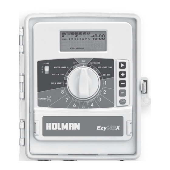
Our EzyOne X works like a clock, sending an electrical signal to solenoid valves located around your garden. These valves divide the system up into zones or STATIONS. This helps to maintain the right amount of pressure for your sprinklers. Each solenoid is
connected to the EzyOne X via an individual cable. To complete the electrical circuit, a COMMON wire runs from the EzyOne X to all your valves. To open a valve (or water a STATION), the EzyOne X sends an electric current to lift a plunger in the solenoid coil.
After the RUN TIME has expired, the electric current is discontinued and the valve closes. The EzyOne X will then automatically open the next valve in the sequence, continuing this way until all allocated STATIONS have been watered. In addition, the EzyOne X
can have up to three different START and RUN TIMES on each station.
Additional Features
RESETTING THE UNIT
STOP ALL WATERING
i. Turn the MAIN DIAL to OFF
1. Turn the MAIN DIAL to OFF
ii. When the display reads
L This will hold all set watering
ALL OFF, press
until the
L This is ideal during wet
display reads CLR ALL
weather to suspend all
iii. Press
until the display
watering until the dial is
turned back to RUN
reads ALL OFF again
ΠAll data will be erased
from the system
SEASONAL WATER SAVING
L Watering durations can be
i. Turn the MAIN DIAL to
adjusted proportionally by a
WATER SAVER %
percentage from 10-100%
ii. Use
L E.g. Water 100% during Summer,
WATER SAVER % shown on the
and 40% during Autumn
display in 10% increments
SYSTEM TEST
i. Turn the MAIN DIAL
L Hint: Use this to automatically
to SYSTEM TEST
run through all stations
on the controller
ii. Each station is pre-set for 2
minutes. Press
to commence
L This is ideal for checking
the operation of your
iii. Press
to scroll
watering system
through stations
L While the system test is running,
iv. Press
to stop it any time
use
or
RUN A START SEQUENCE
i. Turn the MAIN DIAL
L Each STATION 1 through 8
to RUN A START
will run sequentially as per
the set watering durations
ii. Press
to run the
desired RUN TIME
L Press
watering immediately
MANUAL STATION WATERING
L RUN TIME will be set
i. Press
to OFF by default
immediately for the set duration
L Adjust the run time
ii. Press
below 1 or above 255 to
turn the station OFF
FUSE
ΠUse only 1 amp fuse M-205
AUTO BACKUP
L During a power outage without
L Clock time (at the time of
a 9V battery fitted, schedules
the power outage) will be
will still be saved in the
retained in memory
permanent memory chip
9V BATTERY
ΠWe recommend fitting
L When connected to 24V
a 9V alkaline battery to
power pack, the unit will read
maintain clock accuracy
FAULTY BATTERY if the 9V
during power outage
battery is low or not connected
ΠThis battery should
be replaced annually
POWER SUPPLY
This unit runs off a 240V
L Fully compliant with
50Hz single phase outlet,
AS/NZS 61558-2-6
drawing 30W at 240V AC
L 1.25 amp low energy, high
efficiency toroidal transformer
L Internal transformer:
for long life performance
Reduces 240V AC to extra low
voltage supply of 24V AC
L Input: 24V AC 50/60Hz
L Output: Max 1 amp
STN / VALVE 1 LOCATION:
STN / VALVE 2 LOCATION:
Quick Setup Guide
Auto Watering
RUN
L Leave the MAIN DIAL on
RUN to automatically water
as per set schedules
or
to adjust the
START
A
B
C
to adjust test duration
24V AC
to cancel all
to water this station
to stop watering
C
MASTER
1
L To stations:
24V AC 50/60Hz. 0.5 amp max
(up to 2 valves per station)
L To master/pump:
24V AC 0.25, amp max
L Transformer and fuse capacity
must be compatible with
output requirements
STN / VALVE 3 LOCATION:
STN / VALVE 4 LOCATION:
Initial Setup
1
SET CLOCK
i. Turn the MAIN DIAL
to SET CLOCK
ii. Use
to scroll between
minutes, hours and days
iii. Use
or
to adjust time
L Hint: You must have the
current day and time set to
begin setting your watering,
ensuring AM/PM is correct
RUN
OFF
SET CLOCK
WATER SAVER %
SET START TIME
SYSTEM TEST
SET DAY
1
RUN A START
2
8
ON
3
7
OFF
4
6
5
C
M
1 2 3
4 5 6 7 8
M
2
4
6
3
5
7
SOLENOID
COMMON
9V
ALKALINE
BATTERY
ΠOverload protection:
Standard 20mm 1 amp fuse with
faulty station skip function
ΠOutput circuits should be
installed and protected in
accordance with wiring rules
STN / VALVE 5 LOCATION:
STN / VALVE 6 LOCATION:
Auto Watering Setup
2
CHOOSE A START SEQUENCE
i. Set the SLIDER SWITCH
to START A
START
A
B
C
SYSTEM TEST
SLIDER SWITCH
3
RUN A START
SET START TIME
i. Turn the MAIN DIAL to
SET START TIME
ii. Use
or
to adjust time,
ensuring AM/PM is correct
iii. Use
to scroll between
minutes and hours
4
SET DAY
i. Turn the MAIN DIAL to SET DAY
ii. Use
to scroll through
MON to SUN
iii. Use
or
toggle each day
ON or OFF as indicated by
5
24V AC
SET WATERING DURATION PER STATION
i. Use the MAIN DIAL to select
a STATION from 1 to 8
Installation and Wiring
8
MOUNTING THE UNIT
ΠPosition the unit in a place that
is convenient for valve wiring
and near a power source
L Install near a 240V AC outlet
L We recommend mounting
the unit at eye level
VALVES
FIELD WIRING
L Hint: Strip approx. 6mm
of insulation and place this
under the loosened screw,
C
tighten gently and check
the cable is firmly held
ΠA maximum of 2 solenoid valves
can be run off each output
ELECTRICAL CONNECTION
ΠInstallation must be carried
1
out in accordance with these
instructions and all Local,
State and Federal codes
STN / VALVE 7 LOCATION:
STN / VALVE 8 LOCATION:
L Hint: START B and C are
only required if multiple
times are needed per
RUN
station, on different days
OFF
WATER SAVER %
L Press
to delete a start time
8
L Hint: Each station will water a
full RUN TIME and then stop,
then the next station will run in
sequence, one after the other
7
6
5
L Hint: All days MON to SUN
will be set to ON by default
C
M
1 2 3
ii. Adjust the RUN TIME
using
or
i. Drive a #8 screw into the
wall, leaving approx. 4mm
exposed. Use a toggle bolt or
masonry plug if necessary
ii. Hang the unit from the
M
key at the back, ensuring
it is properly seated
iii. Optional: Remove the terminal
cover to add additional screws
through the holes in the lower
corners for extra stability
2
i. Connect one cable from the
terminals to each solenoid valve
ii. Complete the circuit by
looping a common cable to
all valves and connecting to
the COMMON (C) terminal
ΠDisconnect all 240V AC
3
power before commencing
any field wiring or solenoid
valve connection
Advertisement
Table of Contents

Related Manuals for Holman EzyOneX


Summary of Contents for Holman EzyOneX
- Page 1 Quick Setup Guide Our EzyOne X works like a clock, sending an electrical signal to solenoid valves located around your garden. These valves divide the system up into zones or STATIONS. This helps to maintain the right amount of pressure for your sprinklers. Each solenoid is connected to the EzyOne X via an individual cable.
- Page 2 CO1318 User Guide 2019...
- Page 3 Introduction ΠThis 8 station (valve) unit is designed for residential applications ΠStations will water in sequential order 1 through 8 on the start days and times nominated Key Features L WATER SAVER % feature to L Up to 8 stations can be operated reduce all scheduled durations by a fixed percentage...
-
Page 4: Troubleshooting
Holman guarantees this product against defects caused by faulty workmanship and materials for 3 years domestic use from the date of purchase. During this guarantee period Holman will replace any defective product. Packaging and instructions may not be replaced unless faulty. - Page 5 Rain Sensor Connection L A rain sensor detects rainfall and tells the controller to suspend watering, resuming after the sensor dries out L It achieves this by severing the connection between controller and the solenoid valves L To install a rain sensor, wire it to the common, between the controller and valves as shown below: M 1 2 3 4 5 6 7 8 24V AC...
- Page 6 Pump Connection Œ Do not attempt to drive a pump starter directly from the controller L Pump start is provided by connecting one side of the coil from a suitable relay to the MASTER VALVE/PUMP START (P) output of the controller and the other side to the controller common Œ...
- Page 7 Product Review website. www.productreview.com.au then search for our product name Head Office/Service 11 Walters Drive, Osborne Park WA 6017 Tel: +61 8 9416 9999 Fax: +61 8 9416 9920 service@holmanindustries.com.au www.holmanindustries.com.au Copyright © 2019 Holman Industries...
Need help?
Do you have a question about the EzyOneX and is the answer not in the manual?
Questions and answers