Table of Contents
Advertisement
Quick Links
Advertisement
Table of Contents

Related Manuals for Audio Valve Conductor


Summary of Contents for Audio Valve Conductor
- Page 1 INSTRUCTION- MANUAL Con d u c t o r Reference - Tube - Preamplifier This handcrafted product was special made for your high demands, to display the music in its finest way. We guarantee, that this amplifier was carefully produced and tested in all details.
- Page 2 This hand build instrument should give a lifetime of pleasure and with a little care and a full understanding of the operation recommendation in this manual the CONDUCTOR should provide trouble free performance. Please take time to read this manual thoroughly before using your amplifier.
- Page 3 Be sure that you understand the requirements fully before you make any connection to this amplifier or switch ON !! This amplifier CONDUCTOR operates in class - A and is therefore capable of generating a moderately high temperature which requires care full placing to aviod any effect this heat may have on other equipment, furniture and fittings etc.
-
Page 4: Front Panel
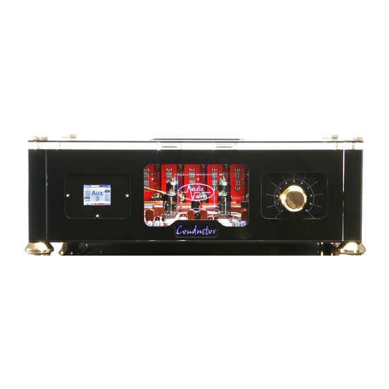
CONDUCTOR reference pre amplifier_ FRONT PANEL The CONDUCTOR is remote controlled designed, this includes also the volume control, but you can handle the functions also manuell. The front panel of the CONDUCTOR is spitted in 3 sections : On the left side is located the TFT graphic display for the optical amplifier status control and also 3 switches which allow the manuell handling of the CONDUCTOR. -
Page 5: Rear Panel
CONDUCTOR reference pre amplifier_ REAR PANEL ( amplifier and power supply ) MAIN VOLTAGE and Main Power Plug ( fuse ) and Main Switch The heavy round duty rocker switch for the main voltage ON /OFF is located on the rear side of the power supply. - Page 6 CONDUCTOR reference pre amplifier_ When the CONDUCTOR is switched on with the the power switch, the TFT display in front of the amplifier shows the AUDIO VALVE logo in a dark shinning mode, and the display of the main power supply is shinning RED. This status shows that the CONDUCTOR is prepared for main power function.
-
Page 7: Placement And Ventilation
. The CONDUCTOR uses for all XLR inputs female jackets and for the output male jackets. The micro - controller handles the use of balanced or unbalanced signals. You have to... -
Page 8: Output Terminals
CONDUCTOR reference pre amplifier_ OUTPUT TERMINALS The CONDUCTOR has two pair of output terminals : XLR and RCA They are manuell selected by the right switch next to the display. You can choose between: - OUTPUT 1; - OUTPUT 2; - OUTPUT 1 + 2... - Page 9 CONDUCTOR reference pre amplifier_ MICRO - CONTROLLER handling the following picture shows the most important routines that controlling your amplifier. By manuell you can operate the amplifier via 3 small touch switches next to the display, or with your remote control.
- Page 10 CONDUCTOR reference pre amplifier_ Input terminal setup menu (configuration) All inputs are configurated as XLR or RCA inputs for the use of balanced or single ended signal phases. To set up your chosen inpust please TURN OFF the power supply by the main switch.
- Page 11 CONDUCTOR reference pre amplifier_ Technical Specifications dual chassis with separate power supply dual mono circuit design, including power supply real symmetric input/output for negative/positive signal phase for both channels non feedback loop input impedance 47 kOhm input sensitive: ( high output source )
- Page 12 We recommend as front tubes the type 6N6P, what gives the amplifier gain from max. 11 db for the unbalanced RCA jackets and 17 dB for balanced XLR jackets connectors. CONDUCTOR`s basic tube placement (2 * 6N6 in front as factory placement) arranges an amplifier`s maximum gain from:...
- Page 13 CONDUCTOR reference pre amplifier CONDUCTOR`s second tube arrangement By using the low and middle level output sources, we recomment as front tubes the type 6922, which give the amplifier a maximum gain from 17 dB in unbalanced and 23 dB in balanced mode.
- Page 14 CONDUCTOR reference pre amplifier_ W A R R A N T Y AUDIOVALVE warrants its components for a two - year period on all electronics and a 90- day period on the tubes from the purchase date. In the event of a failure of your amplifier , AUDIOVALVE will repair or readjust this unit or , should the occasion arise , will replace it provided that all conditions stipulated in this warranty are met.
-
Page 15: Warranty Registration
CONDUCTOR reference pre amplifier_ WARRANTY REGISTRATION Please fill out and return this warranty form to the distributor within 15 days of the purchase date with this form here, or make it online on our webside. • MODEL : _______________________________________________ •... - Page 16 Now press at the same time the volume up and down button together, untill the LED flashes, then stop doing so. If it flashes 1 time, the remote is for the CONDUCTOR 2 times for the EKLIPSE and 3 times for the ASSISTENT 50 / 100.
Need help?
Do you have a question about the Conductor and is the answer not in the manual?
Questions and answers