Advertisement
Quick Links
Visit http://www.ergotron.com/workfi t-sr-install or
use qr code for installation instructional video.
NOTE: 10 feet of cable needed for proper
installation.Extra cables can be found at
www.ergotron.com
For the latest User Installation Guide please visit: www.ergotron.com
User's Guide - English
User's Guide - English
Guía del usuario - Español
Guía del usuario - Español
Manuel de l'utilisateur - Français
Manuel de l'utilisateur - Français
Gebruikersgids - Deutsch
Gebruikersgids - Deutsch
Benutzerhandbuch - Nederlands
Benutzerhandbuch - Nederlands
Guida per l'utente - Italiano
Guida per l'utente - Italiano
Användarhandbok - svenska
Användarhandbok - svenska
ユーザーガイ ド : 日本語
ユーザーガイ ド : 日本語
用户指南 : 汉语
用户指南 : 汉语
888-33-387-G-01 rev. D • 03/16
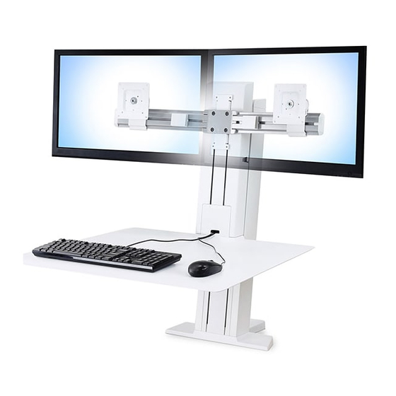
Workfi t -SR, Dual Monitor
®
Do not throw away!
Cardboard blocks needed for
User's Guide
Short Surface
installation.
Includes
Includes
Constant Force™
Constant Force™
Technology
Technology
1 of 20
Advertisement

Subscribe to Our Youtube Channel
Related Manuals for Ergotron Workfit-SR


Summary of Contents for Ergotron Workfit-SR
- Page 1 NOTE: 10 feet of cable needed for proper installation.Extra cables can be found at www.ergotron.com For the latest User Installation Guide please visit: www.ergotron.com User's Guide - English User's Guide - English Guía del usuario - Español Guía del usuario - Español...
- Page 2 DO NOT remove safety guards or labels designed to protect or inform of possible hazards. Only Ergotron-approved installers may service or otherwise modify cart/stand. Failure to heed this Warning may result in serious Personal Injury and Damage both to the cart/stand and equipment.
-
Page 3: Features And Specifications
Features & Specifi cations 5" (127mm) 30° 18.25" (463.55mm) 5 - 13 lbs (2.3 - 5.9 kg) < 26 lbs (11.8 kg) 5 - 12 lbs (2.3 - 5.9 kg) CAUTION: DO NOT EXCEED MAXIMUM LISTED < 5 lbs WEIGHT CAPACITY. SERIOUS INJURY OR (2.2 kg) PROPERTY DAMAGE MAY OCCUR! <... - Page 4 Lay engine down. Attach worksurface to bottom of riser. NOTE: Make sure slots align when installing work surface. 4 of 20 888-33-387-G-01 rev. D • 03/16...
- Page 5 Screw worksurface into riser. M6 x 25mm Disassemble desk clamp. Remove two screws from clamp base. Remove clamp from clamp base. Measure desk thickness. Partially reinstall screws into clamp base.(1.5 revolutions) Desk Thickness 1.1" - 2.4" .4" - 1.4" (28mm - 61mm) (10mm - 36mm) 5 of 20 888-33-387-G-01 rev.
- Page 6 Secure clamp base to riser. Measure desk depth. Back Front Slide clamp base into bottom of riser. Secure clamp base to riser. NOTE: Align the clamp window with the line on the bottom of the riser for your desk depth. Desk Depth M6 x 12mm 30”...
- Page 7 Mount to desk. Two person lift. Use cardboard blocks to support worksurface. Caution: Worksurface not stable until clamp is secured. Secure clamp to clamp base. 7 of 20 888-33-387-G-01 rev. D • 03/16...
- Page 8 Tighten clamp. Caution: Follow the instructions in this manual to securely clamp this product to your mounting surface. Failure to do so may result in equipment damage or personal injury. NOTE: Push clamp base to edge of mounting surface. Remove cardboard blocks from underneath work surface Screw crossbar to riser.
- Page 9 Slide cable routing clips onto crossbar. Lay monitor facedown on worksurface. 9 of 20 888-33-387-G-01 rev. D • 03/16...
- Page 10 OPTIONAL: Insert stop screw to lock portrait/landscape M4x 6mm monitor rotation. 0° Loosely thread thumb screws Attach monitors to mounting brackets. into mounting brackets. M4 x 10mm M4 x 8mm M4 x 10mm Cable Routing Plug power and video cables into monitor by routing through cable clip.
- Page 11 Route cables through cable clips on side Check cable lengths. of riser. Follow relief loop when routing cables. Make sure there is enough cable. (10ft cable recommended) NOTE: Monitor mounting Slide monitor onto crossbar. brackets can be installed upside down to lower monitor 4". 11 of 20 888-33-387-G-01 rev.
- Page 12 Center total width of mounted equipment on stand. Tighten thumb screws to secure monitors. M3 x 6mm Secure end caps to crossbar. Attach end caps to crossbar. 12 of 20 888-33-387-G-01 rev. D • 03/16...
- Page 13 Keyboard and Mouse cables Route mouse and keyboard cables through cable clips on side of riser. Follow relief loop when routing cables. 13 of 20 888-33-387-G-01 rev. D • 03/16...
- Page 14 DO NOT remove safety guards or labels designed to protect or inform of possible hazards. Only Ergotron-approved installers may service or otherwise modify cart/stand. Failure to heed this Warning may result in serious Personal Injury and Damage both to the cart/stand and equipment.
- Page 15 Pivot adjustment. 10mm Increase Lift Strength If the mounted weight is too heavy or this product does not stay up when raised, then you'll need to increase Lift Strength: Decrease Lift Strength If the mounted weight is too light or this product does not stay down when lowered, then you'll need to decrease Lift Strength:...
- Page 16 Test full range of motion Lift riser to highest position. Lower crossbar into lowest position. NOTE: Leave enough slack in cable to allow full range of motion. Caution: To avoid the potential to pinch cables it is important to follow the cable routing instructions in this manual.
- Page 17 Attach side panels. Wrap cables and fasten cable ties Attach front panel. 17 of 20 888-33-387-G-01 rev. D • 03/16...
- Page 18 Attach cap to top. 18 of 20 888-33-387-G-01 rev. D • 03/16...
- Page 19 How to align worksurface to desk. Follow these instructions if worksurface is not aligned to desk properly after installation. Top View Loosen clamp. Rotate Worfi t-SR so that worksurface is parallel to front edge of desk. Secure clamp to desk. 19 of 20 888-33-387-G-01 rev.
- Page 20 • 15 to 20 minutes every 2 hours. For Warranty visit: www.ergotron.com/warranty For Service visit: www.ergotron.com For local customer care phone numbers visit: http://contact.ergotron.com NOTE: When contacting customer service, reference the serial number. © 2015 Ergotron, Inc. All rights reserved.
Need help?
Do you have a question about the Workfit-SR and is the answer not in the manual?
Questions and answers