Advertisement
Quick Links
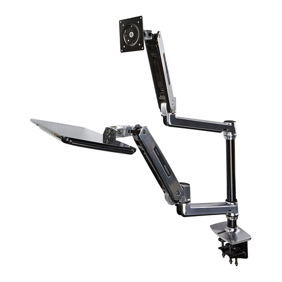
User's Guide
WorkFit LX
™
Sit Stand Desk Mount System
Maximum Screen
Size* = 42"
< 25 lbs
*Limited to 25 lbs
(11.3 kg)
maximum
0-5 lbs
(0-2.3 kg)
CLAMP
GROMMET HOLE
0.78"-2.56"
(20-65mm)
0.78"-2.25" (20-57mm)
0.5"-2.5" (13-64mm)
English
For the latest User Installation Guide please visit: www.ergotron.com
English, Español, Français, Deutsch, Nederlands, Italiano, Svenska, 日本語, 汉语
www.ergotron.com |
|
|
|
USA: 1-800-888-8458
Europe: +31 (0)33-45 45 600
China: 400-120-3051
Japan: japansupport@ergotron.com
888-45-323-G-00 rev.C • 12/18
1 of 19
Advertisement

Subscribe to Our Youtube Channel
Related Manuals for Ergotron WorkFit LX


Summary of Contents for Ergotron WorkFit LX
- Page 1 GROMMET HOLE 0.78"-2.56" (20-65mm) 0.78”-2.25” (20-57mm) 0.5"-2.5" (13-64mm) English For the latest User Installation Guide please visit: www.ergotron.com English, Español, Français, Deutsch, Nederlands, Italiano, Svenska, 日本語, 汉语 www.ergotron.com | USA: 1-800-888-8458 Europe: +31 (0)33-45 45 600 China: 400-120-3051 Japan: japansupport@ergotron.com 888-45-323-G-00 rev.C •...
-
Page 2: Features And Specifications
Features & Specifi cations 360° 70° 360° 20" (508 mm) 180° 5° 180° 90° 20" (508 mm) 5° 180° 360° 3° 3° Safety CAUTION: DO NOT rotate monitor past rear CAUTION: Monitor may edge of desk. Doing so will create an unstable hit Keyboard arm in some situation and may cause equipment damage or confi gurations. -
Page 3: Tools Needed
Components M4 x 12mm M5 x 12mm M6 x 12mm M3 x 6mm M4 x 10mm M4 x 10mm M5 x 7mm M5 x 20mm 2.5mm M8M5 Converter M6 x 45mm 1x 4mm M4 x 8mm 1/4” M4 x 14mm Tools Needed 1/4"... -
Page 4: Desk Placement
Desk Placement Maximum dimensions to allow keyboard arm to CAUTION: Base must be completely on desk surface. lower below front of desk. Failure to follow these instructions may result in equipment damage or personal injury. CLAMP GROMMET HOLE 5.9" 13.3" 11.7"... - Page 5 CLAMP GROMMET HOLE DESK THICKNESS 0.78"-1.38" (20-35mm) 1.18"-2.56" (30-65mm) 1/4” 1/4" CAUTION: Bolt must be centered in hole. 888-45-323-G-00 rev.C • 12/18 5 of 19...
- Page 6 Mount extension and arm to pole. 2.5mm M6 x 45mm 6 of 19 888-45-323-G-00 rev.C • 12/18...
- Page 7 M4 x 8mm 888-45-323-G-00 rev.C • 12/18 7 of 19...
- Page 8 Portrait / Landscape Options OPTION i If you want full portrait/landscape rotation, skip to step 8 on the next page. OPTION ii If you do not want your TV/Monitor to rotate all all, you can stop rotation by inseting the set screw. 0˚...
- Page 9 Check size of TV/Monitor hole TV/Monitor Hole VESA Adapter Pattern Sizes Confi gurations pattern 100mm (3-15/16”) 75mm (2-15/16”) 75x75mm 100x100mm 100mm (3-15/16”) 100x200mm 200mm (7-7/8”) 200x200mm 200mm (7-7/8”) 200x100mm 9 of 19 888-45-323-G-00 rev.C • 12/18...
- Page 10 Mount Type A TV/Monitor to Arm 75x75mm 100x100mm 100mm (3-15/16”) 75mm (2-15/16”) M4 x 10mm M4 x 10mm M4 x 10mm 10 of 19 888-45-323-G-00 rev.C • 12/18...
- Page 11 100x200mm 200x200mm 200x100mm 100mm (3-15/16”) 200mm (7-7/8”) 200mm (7-7/8”) Mount VESA Adapters to Arm based on TV/Monitor hole pattern size (B, C, or D) . M5 x 7mm Mount Type B, C, or D TV/Monitor to Arm M4 x 12mm M5 x 12mm M6 x 12mm NOTE: To reduce M8...
- Page 12 M8M5 KIT Instructions NOTE: Follow this step only if your TV/monitor has M8 holes which need to be reduced to M5. Install M8M5 reducer bushing to TV/Monitor and use M5 x 20 mm monitor screws to secure. M5 x 20mm TV/Monitor Mounting M8 size hole NOTE: Follow this step only for Samsung models using the holder ring.
- Page 13 Mount extension and arm to pole. 2.5mm Part contains grease. Use bag to pr hands from getting greasy. 1x 1x M6 x 45mm 888-45-323-G-00 rev.C • 12/18 13 of 19...
- Page 14 Organize and route cables Leave enough slack in cables to allow full range of motion. 14 of 19 888-45-323-G-00 rev.C • 12/18...
- Page 15 Adjustment Step Important! You will need to adjust this product after installation is complete. Make sure all your equipment is properly installed on the product before attempting adjustments. This product should move smoothly and easily through the full range of motion and stay where you set it. If movements are too easy or diffi cult or if product does not stay in desired positions, follow the adjustment instructions to create smooth and easy movements.
- Page 16 To adjust the TV/monitor tilt: CAUTION: DO NOT remove screw. Removing screw may cause damage to equipment. Increase Lift Strength If the mounted weight is too heavy or this product does not stay up when raised, then you'll need to increase Lift Strength: Decrease Lift Strength If the mounted weight is too light or...
- Page 17 Lift – Up and down CAUTION: DO NOT overtighten fasteners. Increase Lift Strength Overtightening may cause damage to your If the mounted weight is too heavy or equipment. this product does not stay up when raised, then you'll need to increase WARNING Lift Strength: Decrease Lift Strength...
- Page 18 How to remove this tilting feature: 3° 3° Save these screws incase you want to add this feature later. M4 x 14mm 18 of 19 888-45-323-G-00 rev.C • 12/18...
- Page 19 For Warranty visit: www.ergotron.com/warranty For Service visit: www.ergotron.com For local customer care phone numbers visit: http://contact.ergotron.com NOTE: When contacting customer service, reference the serial number. www.ergotron.com | USA: 1-800-888-8458 Europe: +31 (0)33-45 45 600 China: 400-120-3051 Japan: japansupport@ergotron.com © 2015 Ergotron, Inc. All rights reserved. WorkFit is a registered trademark of Ergotron, Inc.
Need help?
Do you have a question about the WorkFit LX and is the answer not in the manual?
Questions and answers