Table of Contents
Advertisement
Advertisement
Table of Contents
Troubleshooting

Related Manuals for Ceridian Dayforce Tuff Clock

Summary of Contents for Ceridian Dayforce Tuff Clock
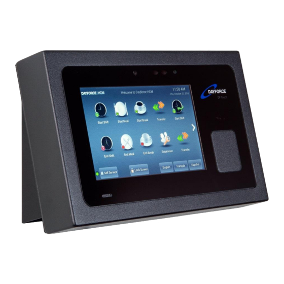
- Page 1 Ceridian’s Dayforce Tuff Clock User Manual [ENG] WARNING: This manual contains information on limitations regarding product use, function and information on the limitation and liability of the manufacturer. Read the entire manual carefully. rev 2Jul2018.
-
Page 2: Important Safety Instructions
Read and save these instructions! Follow all warnings and instructions specified within this document and/or on the equipment. Always ensure you obtain the latest version of the User Guide. Updated versions of this User Guide are available by contacting your Ceridian HCM administrator. IMPORTANT SAFETY INSTRUCTIONS... - Page 3 Page 3 of 31 DF Tuff • Do not apply excessive force to the display surface or adjoining areas. Excessive force will distort the image on the display. • Do not use hard or sharp implements to operate the touchscreen. Operating the touch screen with implements harder than a finger could scratch the display.
-
Page 4: Maintenance
Page 4 of 31 DF Tuff MAINTENANCE With normal use, the system requires minimal maintenance. We recommend, however, that the standby batteries be replaced every 3-5 years. SPECIFICATIONS This document describes the technical specifications of the DF Touch clock terminal. Display and Keypad Capacitive Touch, 7 inch, 800x480 pixels or better, hardened glass surface. -
Page 5: Operating System
Page 5 of 31 DF Tuff IEEE 802.3at Type2, absolute operating input voltage 42.5-57VDC, nominal draw 10Watts, max 18Watts. Optional: External power supply Input voltage 110-250 VAC, 0.5 A, 50/60Hz Optional: Battery backup Discharge life: 1.5 hours at 23°C (73°F) Charge time: 66Hrs (on first use) Charging (normal):... -
Page 6: Time Synchronization
6.10 LED Three-color LED (red, green, blue) for status display 6.11 External USB ports One USB ports for Ceridian approved reader devices. Optional second USB port (Factory installed option).. 6.12 Optional readers & Module (extra cost) Proximity reader (125Khz or 13.56Mhz – for HID Proxpoint™, iClass™, Mifare™, NFC –... -
Page 7: Dimensions (Approximate)
Page 7 of 31 DF Tuff Terminal uses a web service to synchronize its time with Dayforce servers. 6.16 Dimensions (Approximate) 11 in (28cm) wide 6.75 in (17cm) high 4.5 in (7.5cm) deep including angled wall-mount Weight about 4.4 lbs (2Kg) with packaging BATTERY PACK INSTALLATION INSTRUCTIONS Disclaimer: These instructions are for battery pack model L18650-2ACR, manufactured by Fedco Batteries. - Page 8 Page 8 of 31 DF Tuff 7.1.2 Storage and Safety Information for the L18650-2ACR Battery Do not crush, puncture, incinerate, short-circuit, disassemble, immerse in water, expose to strong mineral oxides, or heat the battery over 60 degrees Celsius. Exposure to battery contents may be harmful. In case of eye exposure, flush with water for 15 minutes without rubbing and seek medical attention.
- Page 9 Page 9 of 31 DF Tuff Battery kit Remove the screws on the rear of the chassis, and gently flip back the rear cover so that the inside of the clock is accessible. Step 1: Place the battery between the two battery clips and secure using #4-40 screws through the two middle holes on both sides.
- Page 10 Page 10 of 31 DF Tuff Figure B1: Battery clip assembly. Figure B2: Securing battery into the battery clip assembly. Step 2: Secure battery assembly to mounting posts using four #4-40 screws. Use the four corner holes.
- Page 11 Page 11 of 31 DF Tuff Step 3: Attach battery extension cable to battery as shown in Figure B3. Ensure connectors are attached in the correct orientation. Figure B3: Attaching battery extension cable to battery. Step 4: Attach battery extension cable to main circuit board as shown in Figure B5.
- Page 12 Page 12 of 31 DF Tuff Figure B5: Attaching battery extension cable to main circuit board. Figure B6: Battery installed in clock.
-
Page 13: Charge The Battery
Page 13 of 31 DF Tuff Step 5: Gently flip the rear cover back onto the rear of the enclosure, carefully to fold the wires back into the enclosure without pinching them. Secure the rear cover by installing the screws to hold the cover in place. -
Page 14: Installation Instructions
Page 14 of 31 DF Tuff • The puncher’s face should be well lit and be between 18 and 30 inches from the camera lens (which is on the top center of the screen). • There should not be any other faces in the view of the camera because the software will then not be able to decide which face to capture. - Page 15 Page 15 of 31 DF Tuff Figure 1: Box contents • The wall-mount. • Four screws (#6-32 x 3/8in Philips, for position ‘C’ in Figure 1), and a self-adhesive cable tie for dressing the cables behind the clock if desired. •...
- Page 16 Page 16 of 31 DF Tuff Figure 2: Wall-mount Use the holes marked B in Figure 2 to attach the wall-mount to a standard NEMA electrical box, or the holes marked A to mount the clock to a wall. The recommended height for mounting the clock differs depending on your organization’s needs: •...
- Page 17 Page 17 of 31 DF Tuff Connecting and attaching the clock Note the position of the various connectors on the rear of the clock in Figure 3. The 2 USB and Relay Output/Input are factory options and may not appear on your clock. Figure 3: Rear view of the clock and connections Mount the clock to the wall-mount using the (4) supplied screws as in Figure 4.
- Page 18 Page 18 of 31 DF Tuff Figure 4: Mounted Clock with cables connected Figure 4: Mounted Clock with cables connected...
- Page 19 Page 19 of 31 DF Tuff Note re Power Supply Clocks are supplied with an external low current power pack which delivers 24V DC and plugs directly into the 4-pin Power Input connector on the rear of the unit . The pin (Binder Part Number 09 3431 116 0415) assignments are shown in Figure 5.
- Page 20 Page 20 of 31 DF Tuff The external power pack need not be connected when Power over Ethernet (PoE) is available from the Ethernet switch.
- Page 21 Page 21 of 31 DF Tuff 10 OPTIONAL RELAY MODULE INFORMATION An optional factory-installed Relay Module is available at time of order. The Relay Module contains: • Two Form C relay (contact-closure) outputs; Max Rating 1A at 30V DC. • Two Optically-Isolated Inputs;...
- Page 22 Page 22 of 31 DF Tuff Pin 1, DIGITAL INPUT A Pin 2, DIGITAL INPUT A Pin 3, DIGITAL INPUT B Pin 4, DIGITAL INPUT B Pin 5, RELAY OUTPUT A Pin 6, RELAY OUTPUT A Pin 7, RELAY OUTPUT B Pin 8, RELAY OUTPUT B Figure 8: Relay Module Pinouts, viewed looking at clock connector Figure 9: Field-wireable connector pinouts...
-
Page 23: Networking Information
Ceridian servers in the cloud when powered up and connected to the internet. All clocks must be assigned (registered) to a client in the Ceridian Admin Server by Ceridian personnel. Clocks will not connect if they have not been properly assigned. -
Page 24: Troubleshooting Network Connectivity
“Register Now”’ means that the clock is not connected to the Internet. Clocks with a Ceridian Clock Program Loaded show a round green dot (the status indicator) in the lower left hand of the screen to indicate that the clock is communicating successfully. An orange (yellow) indicator means that there may be a communications problem. - Page 25 Ceridian server. If you get an obviously different message (e.g., “Cannot display the webpage”), then there is an issue preventing access to the Ceridian server. 1. If you get the “Service” page as described in the previous step,...
-
Page 26: Resetting The Clock
Page 26 of 31 DF Tuff 13 RESETTING THE CLOCK: Reset the clock by pressing the reset button next to the connectors below at the rear of the clock. Alternatively, use the Reset control on the Administrator Mode Screen, or (if there is no battery backup installed), temporarily remove external power from clock. - Page 27 Page 27 of 31 DF Tuff 2. Clear the Use Dynamic IP Address check box. 3. Type the following information into the appropriate fields: o IPv4 Address o Subnet Mask o Default Gateway o Primary DNS Server o Secondary DNS server 4.
-
Page 28: Compliance Information
Page 28 of 31 DF Tuff 15 COMPLIANCE INFORMATION FCC STATEMENT This device complies with Part 15 of the FCC Rules. Operation is subject to the following two conditions: (1) This device may not cause harmful interference. (2) This device must accept any interference received, including interference that may cause undesired operation. - Page 29 Page 29 of 31 DF Tuff must not be co-located or operating in conjunction with any other antenna or transmitter. INDUSTRY CANADA STATEMENT This device complies with Industry Canada license-exempt RSS standard(s). Operation is subject to the following two conditions: (1) this device may not cause interference, and (2) this device must accept any interference, including interference that may cause undesired operation of the device.
- Page 30 Page 30 of 31 DF Tuff Model: DFTuff Model: DFTuff-Prox Contains Transmitter Module • FCC ID: 2AJLM-UNT1422 • IC ID: 21879-UNT1422...
- Page 31 Page 31 of 31 DF Tuff 16 CONTACTS USA: Ceridian HCM, Inc 3311 East Old Shakopee Road Minneapolis 55425 MN. For support call +1 866 748-7066 Canada: Ceridian Canada Ltd 125 Gary Street Winnipeg, R3C 3P2 For support call +1 877 237-4342...
Need help?
Do you have a question about the Dayforce Tuff Clock and is the answer not in the manual?
Questions and answers