Table of Contents
Advertisement
Quick Links
Advertisement
Table of Contents

Subscribe to Our Youtube Channel
Related Manuals for Anderson RBMPRO 2000


Summary of Contents for Anderson RBMPRO 2000
- Page 1 404674 Self-loading Trailer RBMPRO 2000 Operator's Manual 2018-2019...
-
Page 3: Table Of Contents
Table of contents How to reach us Starting guidelines Anderson limited warranty About this manual Introduction 1.1 Overview 1.2 Technical specifications 1.3 Machine identification 1.4 Safety and maintenance pictograms Safety precautions 2.1 Basic safety tips 2.2 Safety tips for transport 2.3 Safety tips for hitching... - Page 4 7.5 Adjusting the shock absorber slide chain tension 7.6 Tire pressure 7.7 Maintaining and adjusting the axles 7.8 Maintaining and adjusting the brakes (available as an option) 7.9 Maintaining the high-pressure filter 7.10 Cleaning 7.11 Storage Operator's Manual – Self-loading Trailer Anderson Group...
-
Page 5: How To Reach Us
Please always call your representative first. If your representative is absent or helping another customer, our support team can provide immediate assistance. Anderson service department works in partnership with your dealer. Together, we will ensure any problems you encounter are resolved quickly and efficiently. -
Page 7: Starting Guidelines
Starting guidelines Before starting your Anderson equipment, we strongly recommend that you: Carefully read and understand the contents of this manual Follow all safety guidelines Follow the start-up procedures NOTE: This manual contains important information about equipment maintenance and use. Please give it to the new owner when selling or transferring it. -
Page 9: Anderson Limited Warranty
The one-year warranty begins on the date the new equipment is sold to the customer. If during the year following the purchase of a new equipment, your Anderson equipment fails to function properly due to defective design, materials, manufacturing or assembly, our company will repair your equipment free of charge. - Page 10 Except for conditions or warranties which may not be excluded by law, the selling dealer makes no warranty of its own on any item warranted by Anderson unless it delivers to the purchaser a separate written warranty document specifically warranting the item. The selling dealer has no authority to make any representation or promise on behalf of Anderson or to modify the terms or limitations of this warranty in any way.
-
Page 11: About This Manual
This technical manual will teach you how to maintain and safely operate the self-loading bale carrier. Disclaimer The illustrations and information in this manual are accurate as of printing. Anderson Group reserves the right to modify its machines without prior notice. -
Page 13: Introduction
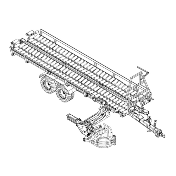
1 Introduction Congratulations! You have just acquired an Anderson self-loading trailer, a quality machine designed specifically for handling wrapped round bales. 1.1 Overview The following figures show the main components of the RBMPRO 2000 trailer. Figure 1 — Main Components of the Self-Loading Trailer The trailer is also equipped with a control box for common operations (see the following figure). - Page 14 Control touch screen (see section 5.1) Electrical power supply cables Trailer connection cable USB port to export client data Fuse CAN bus communication cable (to program the trailer's computer) Control screen On/Off switch Operator's Manual – Self-loading Trailer Anderson Group...
-
Page 15: Technical Specifications
Total width with arm extended (G) 5.71 m (225 in.) Maximum height when unloading (H) 4.88 m (192 in.) Tare weight 7,000 kg (15,432 lb.) GVWR (gross vehicle weight rating) 19,000 kg (41,888 lb.) Anderson Group Self-loading Trailer – Operator's Manual... -
Page 16: Machine Identification
2 or 3 double-acting hydraulic control valves 1.3 Machine identification A 5 x 10 cm (2 x 4 in.) nameplate is located near the trailer arm. It displays the following information about your equipment: Operator's Manual – Self-loading Trailer Anderson Group... -
Page 17: Safety And Maintenance Pictograms
1.4 Safety and maintenance pictograms The RBMPRO 2000 trailer has a number of pictograms that illustrate the main safety and maintenance considerations. Ensure that you see and understand them. Anderson Group Self-loading Trailer – Operator's Manual... - Page 18 Warning! Install the cotter pin and safety chain on the trailer's anchor. Warning! Crushing hazard. Never walk under- neath suspended loads. Before beginning maintenance, install necessary restraints. Operator's Manual – Self-loading Trailer Anderson Group...
- Page 19 Warning! Hydraulic hoses under pressure. See Entretien. Warning! Risk of electrocution by electric wires Warning! Before welding the equipment or working on the electrical system, disconnect the tractor power supply and unplug and remove the control module. Anderson Group Self-loading Trailer – Operator's Manual...
- Page 20 Do not open or remove the guard when the engine is running. Warning! Never climb on the conveyors or the equipment when it is operating. Warning! Falling bales. During work, keep clear of the equipment. Operator's Manual – Self-loading Trailer Anderson Group...
- Page 21 Warning! Components must be locked dur- ing transport. Warning! Disengage the handbrake before moving the trailer. Maximum speed of 25 km/h (15 mph). Anderson Group Self-loading Trailer – Operator's Manual...
-
Page 23: Safety Precautions
2 Safety precautions Your Anderson trailer was designed to minimize risk to the operator. Nevertheless, it must only be used for its intended purpose. Misuse of the trailer may result in injury to the operator. The trailer has a hydraulic system and moving mechanical parts. All these parts may cause serious and even fatal injuries to people and animals. - Page 24 2.1.6 Toxic materials Keep a first aid kit handy. Avoid contact with skin, eyes and mouth when using products such as fuels, oils, solvents and cleaning products, most of which contain harmful substances. Operator's Manual – Self-loading Trailer Anderson Group...
-
Page 25: Safety Tips For Transport
NOTE: The trailer’s standard tires are generally not prescribed for long distances on public roads. NOTE: Make sure the hand brake is not activated before moving the trailer. Anderson Group Self-loading Trailer – Operator's Manual... - Page 26 Insert the loading arm locking pin (Detail C). Close the ball valve for the unloading cylinders (Detail D). Make sure the conveyors are closed. Make sure that the rear stoppers are raised. Figure 5 — Safety Tips for Transport Operator's Manual – Self-loading Trailer Anderson Group...
-
Page 27: Safety Tips For Hitching
Moving parts involve pinching and cutting hazards. Maintenance and repairs must be performed by qualified individuals. Always keep the equipment and its accessories in perfect condition. Keep the oil tanks clean. Follow the maintenance intervals. Anderson Group Self-loading Trailer – Operator's Manual... - Page 28 Before working on the hydraulic system, ensure that it is not pressurized. Relieve the pressure before disconnecting the hydraulic lines. Before repressurizing the hydraulic lines, ensure that all the couplings are correctly tightened. Operator's Manual – Self-loading Trailer Anderson Group...
-
Page 29: Waste Recovery
Return used fluids to a collection and reprocessing centre so that they are recycled or disposed of in accordance with legislation. Stockpiling, abandoning or dumping tires is prohibited, as is burning them outdoors. Return them to an approved distributor or collector. Anderson Group Self-loading Trailer – Operator's Manual... -
Page 31: Getting Started
6. Remove the wheel chocks and disengage the trailer handbrake (if applicable). To unhitch the equipment: 1. Position the equipment on a level and stable surface, turn off the tractor engine and relieve the pressure in the hydraulic hoses. Anderson Group Self-loading Trailer – Operator's Manual... - Page 32 5. Remove the cotter pin from the hitch pin, remove the hitch pin, and remove the safety chain (Figure 6). 6. Uncouple the equipment drawbar from the tractor drawbar. Figure 6 — Hitching to the Tractor Figure 7 — Hydraulic Jack Extended (A) and in Transport Position (B) Operator's Manual – Self-loading Trailer Anderson Group...
- Page 33 If not hitched properly, the equipment could come loose while it is being transported or used. This could injure the operator or other people, or damage the tractor or equipment. Anderson Group Self-loading Trailer – Operator's Manual...
-
Page 34: Connecting The Hydraulic And Electrical Systems
NOTE: Consult the operator's manual for your tractor to identify the hydraulic hoses. To use the RBMPRO 2000 self-loading trailer, the tractor must have: 2 double-acting hydraulic valves (one valve corresponds to one 1/2-in. valve female inlet and outlet); 1 free return fitting;... - Page 35 4. Connect the 12-V power cord (provided with the trailer) directly to the terminal block or the COBO plug inside the tractor. This cord powers the electrical/hydraulic controls and the control screen for the trailer. Anderson Group Self-loading Trailer – Operator's Manual...
- Page 36 3/4- in. fittings (pressure/return) with standard 1/2-in. fittings. With this configuration, the load- sensing hose will not be used. Coil it and store it in a suitable place. Figure 8 — Connecting the Control Box Operator's Manual – Self-loading Trailer Anderson Group...
-
Page 37: Preliminary Maintenance And Initial Testing
2. On the trailer, manually operate the hydraulic controls to test each function (see "Hydraulic controls" on page 67). 3. On the control screen, select manual mode and test each function (see "Operations in manual mode" on page 61). Anderson Group Self-loading Trailer – Operator's Manual... -
Page 39: Adjustments
(Figure 9, B) is greater than 50 mm (2 in.), you will need to adjust the height of the coupler. NOTE: Take the measurements on a level surface when the mixer is empty and uncoupled. Anderson Group Self-loading Trailer – Operator's Manual... -
Page 40: Adjusting The Jack Height
1. Hitch the trailer to the tractor. 2. Remove the mounting bolts from the jack. 3. Slide the jack to the desired height. 4. Re-insert the mounting bolts in the jack. 5. Unhitch the trailer from the tractor. Operator's Manual – Self-loading Trailer Anderson Group... - Page 41 NOTE: In transport mode, the jack must be folded up and the lever must be placed on its support (Figure 10). Figure 10 — Hydraulic Jack Extended (A) and in Transport Position (B) Anderson Group Self-loading Trailer – Operator's Manual...
-
Page 42: Adjusting The Bale Guides And Bale Guide Roller
Figure 11 — Adjusting the Bale Guides (Detail A) and Bale Guide Roller (Detail B) Table 5 — Position of the Bale Guides and Bale Guide Roller Based on the Diameter of Bales Position Bale diameter 1.2 m (4 ft.) 1.35 to 1.5 m (4.5 to 5 ft.) Operator's Manual – Self-loading Trailer Anderson Group... -
Page 43: Adjusting The Width Of The Conveyors
(Figure 13). Figure 12 — Location of the Visual Indicator Figure 13 — Visual Indicator Anderson Group Self-loading Trailer – Operator's Manual... -
Page 44: Adjusting The Front Stopper
Figure 14 — Adjusting the Front Stopper Table 6 — Position of the Front Stopper Based on the Diameter of Bales Position Bale diameter 1.2 m (4 ft.) 1.35 to 1.5 m (4.5 to 5 ft.) Operator's Manual – Self-loading Trailer Anderson Group... -
Page 45: Adjusting The Pusher Travel Stroke
LS_PO_M1 sensor that detects when the pusher is in middle 1 position and that corresponds to the distance travelled by the pusher once the row is complete. Figure 15 — Position of the Sensors to Adjust the Pusher Travel Stroke Anderson Group Self-loading Trailer – Operator's Manual... -
Page 47: Operation
Allows you to select modes, menus and operations. Simulates a bale being loaded. For testing purposes only; do not use. Move the cursor to the right or left when adjusting the date and time. Anderson Group Self-loading Trailer – Operator's Manual... - Page 48 In the main menu, you can also access the settings menu and activate the emergency stop. Figure 17 — Main Menu on the Control Screen Table 8 describes the various options in the main menu. Operator's Manual – Self-loading Trailer Anderson Group...
- Page 49 53) and adjusting the client bale counters (see "Adjusting the counters and exporting the data" on page 63). Opens the menu for adjusting the bale counter on the trailer (see "Adjusting the counters and exporting the data" on page 63). Anderson Group Self-loading Trailer – Operator's Manual...
- Page 50 "Adjusting the loading arm angle and grabbing pressure" on page 63). Allows you to select the control screen language (English , French or Spanish Opens the factory settings screen. Note: A code is required to access this menu. Operator's Manual – Self-loading Trailer Anderson Group...
-
Page 51: Loading Bales
Displays the function associated with the option selected in the main menu. 5.2 Loading bales The RBMPRO 2000 trailer collects bales in the position that the baler placed them on the ground (vertical or horizontal). When using the trailer, the loading arm should never touch the ground. - Page 52 The MAX column shows the maximum number of bales that can be loaded for the selected dimensions. In some cases, two options are available for the maximum number of bales. Select the maximum number of bales you want to load. Operator's Manual – Self-loading Trailer Anderson Group...
- Page 53 You can associate a loading job with a particular client to track the number of bales loaded for that client. To select a client or enter a new client: 1. In the main menu or on the loading screen, press . The following screen will appear: Figure 20 — Client Data Screen Anderson Group Self-loading Trailer – Operator's Manual...
- Page 54 To load bales: 1. In the main menu, select . The various trailer components will move into loading position, and the following screen will appear: Figure 21 — Automatic Loading in Progress Screen Operator's Manual – Self-loading Trailer Anderson Group...
- Page 55 To stop loading before the trailer is completely full, press . The loading arm will automatically be raised 10 degrees. To resume loading, press again. The automatic loading process will resume where it left off. Anderson Group Self-loading Trailer – Operator's Manual...
- Page 56 (see section 5.2.1). NOTE: Never load a bale on top of the first two bales that are loaded. The bale could fall off the trailer when the trailer is fully loaded. Operator's Manual – Self-loading Trailer Anderson Group...
- Page 57 Figure 22 — Steps for Loading Vertical Bales Anderson Group Self-loading Trailer – Operator's Manual...
- Page 58 Figure 23 — Steps for Loading Horizontal Bales Operator's Manual – Self-loading Trailer Anderson Group...
-
Page 59: Unloading Bales
Use the camera to see what is happening behind the trailer. To activate the rear camera, press 3. Using the tractor's hydraulic controls, raise the platform all the way to unload horizontal bales, or raise the platform halfway to unload vertical bales. Anderson Group Self-loading Trailer – Operator's Manual... - Page 60 Figure 26 — Unloading Screen, Step Three 8. Lower the platform into its original position and then press . Automatically: The pusher will return to the front of the trailer; The rear stoppers will be raised; Operator's Manual – Self-loading Trailer Anderson Group...
-
Page 61: Operations In Manual Mode
1. In the main menu, press . The following screen will appear: Figure 27 — Manual Mode Screen NOTE: Use the camera to see what is happening behind the trailer. To activate the rear camera, press Anderson Group Self-loading Trailer – Operator's Manual... - Page 62 Extends ( ) and retracts ( ) pivot #3 on the loading arm Pivots pivot #2 on the loading arm clockwise ( ) and counter-clockwise ( ) Raises ( ) and lowers ( ) the rear stoppers Operator's Manual – Self-Loading Trailer Anderson Group...
-
Page 63: Adjusting The Loading Arm Angle And Grabbing Pressure
5. Press to return to the settings menu. 5.6 Adjusting the counters and exporting the data 5.6.1 Correcting the bale counter To correct the number shown in the bale counter on the trailer: Anderson Group Self-loading Trailer – Operator's Manual... - Page 64 Figure 30 — Bale Counter Screen 2. Press to adjust the number of bales. 3. Press to return to the settings menu. 5.6.2 Correcting the client bale counter To modify the bale counter for a client: Operator's Manual – Self-loading Trailer Anderson Group...
- Page 65 3. When a message pops up to indicate that the export is complete, remove the USB key. The name of the exported file will be in mmddhhhh.csv format by default, such as 04280923.csv. Anderson Group Self-loading Trailer – Operator's Manual...
-
Page 67: Troubleshooting
The hydraulic controls must never be used if the trailer can be put in motion. Before using the hydraulic controls, ensure that no one will operate the controls at the same time on the tractor. Anderson Group Self-Loading Trailer – Operator's Manual... - Page 68 Extends ( ) and retracts ( ) pivot #3 on the loading arm Pivots pivot #2 on the loading arm clockwise ( ) and counter-clockwise ( ) Raises ( ) and lowers ( ) the rear stoppers Operator's Manual – Self-Loading Trailer Anderson Group...
-
Page 69: Sensors
If a sensor stops working properly while the trailer is in use, the operation that is underway will automatically stop and the following screen will appear to show which sensor is causing the problem. Anderson Group Self-loading Trailer – Operator's Manual... - Page 70 Detects when the pusher is in middle 2 position Figure 37 MC050-C1P25 LS_PO_R Detects when the pusher is in front position Figure 37 MC050-C1P26 LS_PO_M1 Detects when the pusher is in middle 1 position Figure 37 Operator's Manual – Self-loading Trailer Anderson Group...
- Page 71 MC050-C1P29 LS pressure Measures the pressure in the hydraulic system Figure 38 Arm angle Detects the angle of the arm Figure 38 Figure 35 — Locations of the Bale and Shock Absorber Slide Sensors Anderson Group Self-loading Trailer – Operator's Manual...
- Page 72 Figure 36 — Locations of the Pivot and Arm Extension Sensors Figure 37 — Locations of the Pusher Middle Position Sensors Operator's Manual – Self-loading Trailer Anderson Group...
- Page 73 Figure 38 — Location of the Pusher Rear Position Sensor Figure 39 — Locations of the Pressure and Arm Angle Sensors Anderson Group Self-loading Trailer – Operator's Manual...
-
Page 74: Common Problems
The fuse has Replace the fuse. blown. The control screen multi- con- Plug in the connector. has no power. nector unplugged. The main cable is Repair or replace the cable. damaged. Operator's Manual – Self-loading Trailer Anderson Group... - Page 75 Disassemble, clean and reassemble the hydraulic components are not valve is blocked. spool valve. moving properly. The hydraulic load- Replace the hydraulic load-sensing valve. sensing valve defective. The system is losing filters Replace the filters. pressure. blocked. Anderson Group Self-loading Trailer – Operator's Manual...
- Page 76 52). form, they get too jammed together. For any other problems, please contact your dealer or our technical service department. Operator's Manual – Self-loading Trailer Anderson Group...
-
Page 77: Maintenance
A safety stand is provided so that you can safely perform maintenance and repairs underneath the trailer platform. The stand is stored on the side of the trailer, as shown in Figure 40. Anderson Group Self-loading Trailer – Operator's Manual... - Page 78 3. Insert the locking pin in the hole and insert the cotter pin to keep it in place. 4. Slowly lower the platform until its weight is resting on the stand. Figure 41 — Setting Up the Safety Stand Ensure that you do not crush the stand. Operator's Manual – Self-loading Trailer Anderson Group...
-
Page 79: Maintenance Schedule
(hay, dust, 7.10 etc.) Check tire pressure section Check that the lug nuts are tight section Check that the hubcaps section attached securely Check the wheel bearing play section Lubricate wheel bearings section Anderson Group Self-loading Trailer – Operator's Manual... - Page 80 Adjust the brake slack section Lubricate the cyl- inder joints section Lubricate the tan- dem axle pivots section Lubricate drawbar pivot (1) section Lubricate wheel bearings section Lubricate bearings section Lubricate transmission section chains Operator's Manual – Self-loading Trailer Anderson Group...
-
Page 81: Lubrication
Adjust the shock absorber slide section chain tension 7.2 Lubrication Your self-loading trailer must be lubricated using a gun in various places indicated by the sticker in the following figure: Anderson Group Self-loading Trailer – Operator's Manual... - Page 82 Figure 42 – Lubrication point marker NOTE: Anderson Group recommends using synthetic grease. Table 15 — Lubrication Frequency Part (number of lubrication points) Every 50 hours of use Tandem axle pivots (4) Drawbar pivot (1) All other pivots (17) All cylinder joints (22)
- Page 83 Figure 44 — Platform Lubrication Points Figure 45 — Drawbar Lubrication Points Anderson Group Self-loading Trailer – Operator's Manual...
- Page 84 Figure 46 — Pusher Chain Bearings Figure 47 — Pusher Transmission Chain Bearings Operator's Manual – Self-loading Trailer Anderson Group...
- Page 85 Figure 48 — Rear Stopper Pivots Figure 49 — Loading Arm Lubrication Points Anderson Group Self-loading Trailer – Operator's Manual...
-
Page 86: Adjusting The Pusher Chain Tension
Tighten the two tension bolts an equal amount, ensuring that the visible parts of both bolts are the same length. 3. Tighten the eight bolts on both sides of the chain box (A, Figure 51). Operator's Manual – Self-loading Trailer Anderson Group... -
Page 87: Adjusting The Pusher Transmission Chain Tension
2. Tighten the nut on the tension bolt underneath the transmission (B, Figure 52) until the correct tension is reached. 3. Tighten the four bolts on the side of the transmission (A, Figure 52). Figure 52 — Adjusting the Pusher Transmission Chain Tension Anderson Group Self-loading Trailer – Operator's Manual... -
Page 88: Adjusting The Shock Absorber Slide Chain Tension
The holes in the rim must be countersunk to fit the spherical part of the washer or the tapered part of the nut. The nuts are tightened once the spherical part of the washer or the tapered part of the nut is in the countersunk hole. Operator's Manual – Self-loading Trailer Anderson Group... - Page 89 7.7.2 Tightening the lug nuts Using a torque wrench, the nuts must be gradually tightened one after another in the order shown in Figure 55. Figure 55 — Order for Tightening the Nuts Anderson Group Self-loading Trailer – Operator's Manual...
- Page 90 After the first 50 hours or 1,000 km; Every 6 months or 25,000 km. To check the wheel bearings: 1. Lift the wheel slightly off the ground. 2. Slowly turn the wheel in both directions to check for any resistance. Operator's Manual – Self-loading Trailer Anderson Group...
- Page 91 9. Put the hubcap back on. 10. Put the wheel back on (see section 7.7.1 and section 7.7.2). Once the wheel is back on, turn it slightly. The wheel should come to rest with a slight rocking movement. Anderson Group Self-loading Trailer – Operator's Manual...
- Page 92 Inner bearing Inner bearing grease retainer Outer bearing grease retainer Outer bearing Castle nut Hair pin clip or cotter pin Hubcap gasket Hubcap Hubcap screws 7.7.6 Lubricating the wheel bearings Lubricate the wheel bearings: Operator's Manual – Self-loading Trailer Anderson Group...
- Page 93 11. Repeat the process for the hub. 12. Check the contact surface of the castle nut. 13. Clean and degrease all these parts with a suitable product. To reassemble and lubricate the wheel bearings: Anderson Group Self-loading Trailer – Operator's Manual...
- Page 94 9. Lock the castle nut with a new cotter pin or the hair pin clip, as appropriate. 10. For hubs without grease retainers, fill the hubcap with grease. 11. Put the hubcap back on. Figure 57 — Disassembling the Wheel Bearings Operator's Manual – Self-loading Trailer Anderson Group...
- Page 95 3. Insert the outer races as shown in Figure 60. NOTE: Make sure to put the outer races and grease retainers in the correct positions. Anderson Group Self-loading Trailer – Operator's Manual...
-
Page 96: Maintaining And Adjusting The Brakes (Available As An Option)
When getting started and after the first loaded run, check that the brakes are working properly: Check that the actuators and return springs are secured and check the forward and return travel of the cylinders. Check that the service and parking brakes are working properly. Operator's Manual – Self-loading Trailer Anderson Group... - Page 97 If a slack adjuster has been installed, turn the adjusting screw on the slack adjuster to adjust its relative position to the cam bearing (see Figure 62). Anderson Group Self-loading Trailer – Operator's Manual...
- Page 98 During this process, inspect all the brake mechanisms: The condition of and wear on the drums. The condition of the cam shafts and brake levers, especially the play on the splines. Operator's Manual – Self-loading Trailer Anderson Group...
-
Page 99: Maintaining The High-Pressure Filter
The condition of the high-pressure filter on the trailer must be checked after every 50 hours of use. The filter is underneath the frame, on the left side, behind the tongue (Figure 64). Anderson Group Self-loading Trailer – Operator's Manual... -
Page 100: Cleaning
If you do not plan on using the trailer for a long period, store it in a place with a flat surface. For your safety, chock the wheels to prevent the trailer from moving. NOTE: Anderson Group strongly recommends cleaning and performing general maintenance on the machine before storing it for long periods. Operator's Manual – Self-loading Trailer... - Page 101 ANDERSON GROUP 5125 De la Plaisance Chesterville, QC CANADA G0P 1J0 Email: service@grpanderson.com Phone: 1-819-382-2952 Fax: 1-819-382-2218 www.grpanderson.com...
Need help?
Do you have a question about the RBMPRO 2000 and is the answer not in the manual?
Questions and answers