Advertisement
Quick Links
FOSC 450-ab-c-dd-e-fgh
a = Closure size
b = Number of cable ports (6 for B-size)
c = Number of cable ports for which termination hardware
is provided (typically all ports or 2 ports)
dd = Capacity or type of splice tray (12, 24, NT [no trays])
e = Number of trays pre-installed (1 or 0 [NT] is standard)
f = Basket type (N=none or B)
g = Number of ground feed-thru lugs (0 or 3)
h = Valve for flash test (V = Yes [standard], N = No)
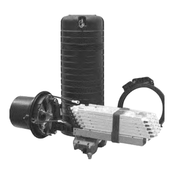
FOSC 450 B6
Closure
I N S T A L L A T I O N
Fiber Optic Splice Closure
1.0 General Product Description
The FOSC 450 fiber optic splice closures use compressed-gel cable
seals to environmentally seal fiber cable splice points.
The maximum single splice capacity of the FOSC 450 B6 closure is
144 with 24 splices stored on six trays. The maximum mass fusion
splice capacity is 288, only four trays are needed.
A larger FOSC 450 D6 closure is also available. Splice capacities for
the D size are 576 for single splicing and 1152 for mass splicing.
Note: Cable blocking is not recommended in this closure due
to the space constraints. If cable blocking is used, follow the
special instructions in "D/Gel Cable Block" installation instruc-
tions.
2.0 Kit Contents
• Dome and clamp
• Base and o-ring
• Metal slack basket (optional)
• Gel end-piece
• Velcro strap
• 4 Gel end-piece plugs
• 2 or 6 Cable strain relief holders and cable clips
• Hose clamps
• 6 Small and 2 large strength member attachment brackets
with lugs
• 3 Bond clamps (3" long) -- optional
• 3 Braided grounding straps -- optional
• 12 Small tie wraps
• 1/4" Nut driver to install hose clamp
• Installation Instructions
1
I N S T R U C T I O N
Advertisement

Related Manuals for Tyco Electronics FOSC 450 B6

Summary of Contents for Tyco Electronics FOSC 450 B6
- Page 1 The FOSC 450 fiber optic splice closures use compressed-gel cable seals to environmentally seal fiber cable splice points. FOSC 450-ab-c-dd-e-fgh The maximum single splice capacity of the FOSC 450 B6 closure is a = Closure size 144 with 24 splices stored on six trays. The maximum mass fusion b = Number of cable ports (6 for B-size) splice capacity is 288, only four trays are needed.
-
Page 2: Cable Preparation
Other Accessory Kits: Use these accessory kits to seal multiple small cables in a single port: • FOSC-ACC-B-Tray-12, 16 and 24 (tray kit) FAK-450SEAL-1-NO/CBL-AT • FOSC-450-Cable-Term-4-N or FOSC-450-Cable-Term-4-G (ground- ing). Contains 4 replacement cable termination components, can be Closure type ordered with or without grounding. - Page 3 Note: Do not use a braided or stranded ground wire when installing a ground through a port on any Tyco Electronics fiber optic splice closure. Tyco Electronics requires a solid, bonded ground wire to prevent a leak path and create a proper seal.
-
Page 4: Cable Installation
Do not use a braided or strand- ed ground wire when installing a ground through a port on any Tyco Electronics fiber optic splice closure. Tyco Electronics requires a solid, bonded ground wire to prevent a leak path and create a proper seal. -
Page 5: Cable Routing
6.0 Cable Routing Note: If this is a new closure, remove any installed trays that might make fiber routing easier. Install trays as you go. Refer to section 4.0 for cable preparation. Go to: 6.1 for Loose Buffer Tube Cable 6.2 for Central Core Tube Cable 6.1 Loose Buffer Tube Cable Installation 1. - Page 6 6.2 Central Core Tube Cable Installation 1. If cable(s) enter through the bottom two ports (5 & 6), core tubes can be routed directly to the slack basket or non-hinging bottom tray and secured with tie-wraps - do not over tighten. The core tubes should already be cut to 6"...
- Page 7 3. Feed arrangement of designated ribbons (groups of six) into the tubes in the basket and pull ribbons through transportation tubes onto the tray- leaving a small loop in basket. Ribbons on one side of trans- portation tube may need to be oriented in an opposite order to prevent crossover of ribbons on the tray.
- Page 8 Important: After flash testing, bleed all pressure from the closure through the valve 9.0 Mounting Closure The FOSC 450 B6 kit can be mounted to an aerial strand, to a wall, or to a pole using these supplementary kits: Aerial Mount...
Need help?
Do you have a question about the FOSC 450 B6 and is the answer not in the manual?
Questions and answers