Table of Contents
Advertisement
Quick Links
Advertisement
Table of Contents

Subscribe to Our Youtube Channel
Related Manuals for HiLook IK-4142B-MH


Summary of Contents for HiLook IK-4142B-MH
- Page 1 Network Bullet Camera Quick Start Guide...
- Page 2 Network Bullet Camera·Quick Start Guide Quick Start Guide COPYRIGHT © 2018 Hangzhou Hikvision Digital Technology Co., Ltd. ALL RIGHTS RESERVED. Any and all information, including, among others, wordings, pictures, graphs are the properties of Hangzhou Hikvision Digital Technology Co., Ltd. or its subsidiaries (hereinafter referred to be “Hikvision”). This user manual (hereinafter referred to be “the Manual”) cannot be reproduced, changed, translated, or distributed, partially or wholly, by any means, without the prior written permission of...
- Page 3 Network Bullet Camera·Quick Start Guide Legal Disclaimer TO THE MAXIMUM EXTENT PERMITTED BY APPLICABLE LAW, THE PRODUCT DESCRIBED, WITH ITS HARDWARE, SOFTWARE AND FIRMWARE, IS PROVIDED “AS IS”, WITH ALL FAULTS AND ERRORS, AND HIKVISION MAKES NO WARRANTIES, EXPRESS OR IMPLIED, INCLUDING WITHOUT LIMITATION, MERCHANTABILITY, SATISFACTORY QUALITY, FITNESS FOR A PARTICULAR PURPOSE, AND NON-INFRINGEMENT OF THIRD PARTY.
- Page 4 Network Bullet Camera·Quick Start Guide IN THE EVENT OF ANY CONFLICTS BETWEEN THIS MANUAL AND THE APPLICABLE LAW, THE LATER PREVAILS. Regulatory Information FCC Information FCC compliance: This equipment has been tested and found to comply with the limits for a digital device, pursuant to part 15 of the FCC Rules.
- Page 5 Network Bullet Camera·Quick Start Guide 2012/19/EU (WEEE directive): Products marked with this symbol cannot be disposed of as unsorted municipal waste in the European Union. For proper recycling, return this product to your local supplier upon the purchase of equivalent new equipment, or dispose of it at designated collection points.
- Page 6 Network Bullet Camera·Quick Start Guide Warnings Follow these Cautions Follow these safeguards to prevent precautions to prevent serious injury or death. potential injury or material damage. Warnings For Network Camera: ● Proper configuration of all passwords and other security settings is the responsibility of the installer and/or end-user. ●...
- Page 7 Network Bullet Camera·Quick Start Guide ● If smoke, odor or noise rise from the device, turn off the power at once and unplug the power cable, and then please contact the service center. For NVR Device: ● Proper configuration of all passwords and other security settings is the responsibility of the installer and/or end-user.
- Page 8 Network Bullet Camera·Quick Start Guide Cautions For Network Camera: ● Make sure the power supply voltage is correct before using the camera. ● Do not drop the camera or subject it to physical shock. ● Do not touch sensor modules with fingers. If cleaning is necessary, use clean cloth with a bit of ethanol and wipe it gently.
- Page 9 Network Bullet Camera·Quick Start Guide ● While in delivery, the camera shall be packed in its original packing, or packing of the same texture. ● Regular part replacement: a few parts (e.g. electrolytic capacitor) of the equipment shall be replaced regularly according to their average enduring time.
- Page 10 Network Bullet Camera·Quick Start Guide ● Ensure unit is properly secured to a rack or shelf. Major shocks or jolts to the unit as a result of dropping it may cause damage to the sensitive electronics within the unit. ● Use the device in conjunction with an UPS if possible. ●...
-
Page 11: Table Of Contents
Network Bullet Camera·Quick Start Guide Table of Contents 1 Introduction ................11 1.1 Application ................. 11 1.2 NVR Appearance ..............12 1.2.1 Front Panel.............. 12 1.2.2 Rear Panel ............... 13 1.3 Camera Appearance ............14 2 NVR Installation ................ 16 2.1 Precautions ................ -
Page 12: Introduction
Network Bullet Camera·Quick Start Guide 1 Introduction Application The Wi-Fi kit includes four network cameras and a NVR device. The NVR works as a wireless network router, and the camera connects to the NVR's Wi-Fi automatically after the camera is powered on. Monitor Wi-Fi Camera VGA/HDMI... -
Page 13: Nvr Appearance
Network Bullet Camera·Quick Start Guide 1.2 NVR Appearance 1.2.1 Front Panel Front Panel Description Icon Description Indicator turns red when NVR is powered up. Indicator lights in red when there is data transmission. Indicator blinks blue when network connection is functioning properly. -
Page 14: Rear Panel
Network Bullet Camera·Quick Start Guide 1.2.2 Rear Panel Rear Panel Description Icon Description Wi-Fi Antenna Wi-Fi antenna interface. Power supply 12 VDC power supply. Audio out One audio output. VGA interface HDMI HDMI video output connector. One RJ-45 10M/100M self-adaptive Ethernet interface Wi-Fi Antenna Wi-Fi antenna interface. -
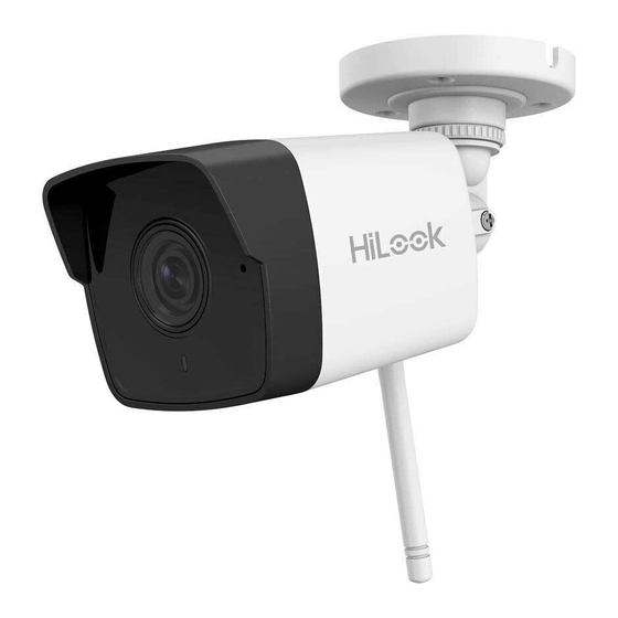
Page 15: Camera Appearance
Network Bullet Camera·Quick Start Guide Icon Description Two USB 2.0 interface. Ground Ground (needs to be connected when device starts up). Camera Appearance Overview Description Description Lens IR LED Cover... - Page 16 Network Bullet Camera·Quick Start Guide Description Status Indicator ● Flashing Blue: Normal Wi-Fi connection. ● Solid Red: The camera is during startup. ● Flashing red and blue: The camera has started and starts Wi-Fi configuration. ● Flashing Red: Fast Flashing: The network connection failed.
-
Page 17: Nvr Installation
Network Bullet Camera·Quick Start Guide 2 NVR Installation Precautions During installation of the NVR: Use brackets for rack mounting. Ensure ample room for audio and video cables. When routing cables, ensure that the bend radius of the cables is no less than five times than its diameter. - Page 18 Network Bullet Camera·Quick Start Guide Steps: 1. Remove the cover from device by unfastening the screws on panels. Remove Cover 2. Connect the data cable and power cable. Connect one end of data cable to the device motherboard. Connect the other end of data cable to HDD. Connect one end of power cable to HDD.
- Page 19 Network Bullet Camera·Quick Start Guide Connect Cables 3. Set the device up, match HDD screw threads with the reserved holes on the device bottom, and fix HDD with screws. Fix HDD to Device Bottom 4. (Optional) Repeat the steps above to install other HDDs. 5.
-
Page 20: Camera Installation
Network Bullet Camera·Quick Start Guide 3 Camera Installation Before you start: ● Make sure the device in the package is in good condition and all the assembly parts are included. ● The standard power supply is 12 VDC. Make sure your power supply matches with your camera. -
Page 21: Wall/Ceiling Mounting
Network Bullet Camera·Quick Start Guide Install the Antenna 3.2 Wall/Ceiling Mounting Steps: 1. Paste the drill template on the wall or ceiling and drill holes according to the marked holes on the drill template. - Page 22 Network Bullet Camera·Quick Start Guide Screw Hole Screw Hole Screw Hole Drill the Holes 2. If you need to route cables through the wall or ceiling, cut a cable hole according to the drill template. Skip this step if you want to route the cables on the surface of the wall or ceiling.
- Page 23 Network Bullet Camera·Quick Start Guide Install the Camera 5. Adjust the view angle of the camera. Loosen the fixing ring to adjust the pan angle. Loosen the adjusting screw 1 ring to adjust the tilt angle. Loosen the adjusting screw 2 to adjust the rotation angle. Tighten the fixing ring and the adjusting screws.
-
Page 24: Waterproof Measures
Network Bullet Camera·Quick Start Guide Waterproof Measures If the camera is installed outdoor, you should use the waterproof accessory or tapes to waterproof the cables. Otherwise the cables might get wet or a short circuit occurs. 3.3.1 Waterproof Network Cable Use the waterproof accessory to waterproof the network cable after the camera is secured on the installation surface. - Page 25 Network Bullet Camera·Quick Start Guide Components Network Cable from Router/Switch Steps: Feed the plugless network cable ⑦ through the lock nut ⑥, waterproof the rubber gasket ⑤ (rubber gasket inset ridge must face waterproof endcap), and the waterproof endcap ④ in order.
-
Page 26: Waterproof Other Cables
Network Bullet Camera·Quick Start Guide Align the snap and notch. i. Insert into ⑤ ④ ii. Secure with ⑥ ④ Camera Switch/Router Waterproof Accessory Installation 3.3.2 Waterproof Other Cables After routing and connecting the cables, use the waterproof tapes to wrap up the cables. - Page 27 Network Bullet Camera·Quick Start Guide Waterproof Cables...
-
Page 28: Menu Operation
Network Bullet Camera·Quick Start Guide 4 Menu Operation Startup and Shutdown To start your NVR: Steps: 1. Check the power supply is plugged into an electrical outlet. It is HIGHLY recommended that an Uninterruptible Power Supply (UPS) be used in conjunction with the device. The Power button on the front panel should be red, indicating the device is receiving the power. -
Page 29: Use The Setup Wizard
Network Bullet Camera·Quick Start Guide For the first-time access, you need to activate the NVR by setting an admin password. No operation is allowed before activation. You can also activate the NVR via Web Browser, SADP or client software. 1. Input the same password in the text field of Create New Password and Confirm New Password. -
Page 30: Add Ip Cameras
Network Bullet Camera·Quick Start Guide Add IP Cameras 4.4.1 Wi-Fi Kit Cameras The supplied Wi-Fi kit cameras can connect to the NVR automatically after it is powered on. 4.4.2 Other Cameras For the other cameras, follow the steps below to configure the Wi-Fi parameters and add the cameras. - Page 31 Network Bullet Camera·Quick Start Guide Steps: 1. Download and install the Hik-Connect app by searching "Hik-Connect" in App Store or Google Play 2. Launch the app and register for a Hik-Connect user account. 3. Log in Hik-Connect app after registration. 4.
- Page 32 UD12188B...
Need help?
Do you have a question about the IK-4142B-MH and is the answer not in the manual?
Questions and answers