Advertisement
SERVICE MANUAL
VIDEO CASSETTE RECORDER
7
YD007
2004
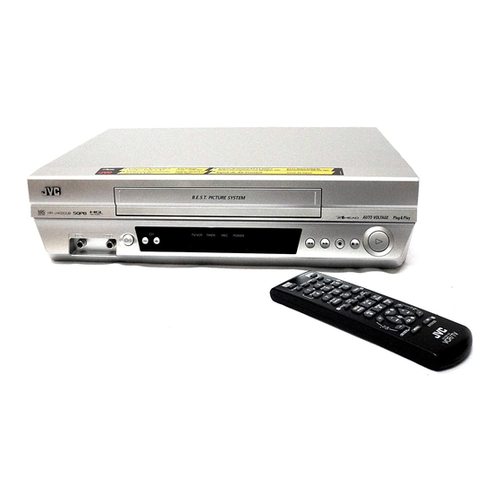
HR-J4020UA, HR-J4020UB,
HR-J7020UA, HR-J7020UM
For disassembling and assembling of MECHANISM ASSEMBLY, refer to the SERVICE MANUAL No.86700(MECHANISM ASSEMBLY).
1
PRECAUTION. . . . . . . . . . . . . . . . . . . . . . . . . . . . . . . . . . . . . . . . . . . . . . . . . . . . . . . . . . . . . . . . . . . . . . . . . 1-3
2
SPECIFIC SERVICE INSTRUCTIONS . . . . . . . . . . . . . . . . . . . . . . . . . . . . . . . . . . . . . . . . . . . . . . . . . . . . . . 1-5
3
DISASSEMBLY . . . . . . . . . . . . . . . . . . . . . . . . . . . . . . . . . . . . . . . . . . . . . . . . . . . . . . . . . . . . . . . . . . . . . . . 1-8
4
ADJUSTMENT . . . . . . . . . . . . . . . . . . . . . . . . . . . . . . . . . . . . . . . . . . . . . . . . . . . . . . . . . . . . . . . . . . . . . . . 1-10
5
TROUBLESHOOTING . . . . . . . . . . . . . . . . . . . . . . . . . . . . . . . . . . . . . . . . . . . . . . . . . . . . . . . . . . . . . . . . . 1-14
HR-J4020UA, HR-J4020UB,
HR-J7020UA, HR-J7020UM [V17C1, V17D0]
TABLE OF CONTENTS
COPYRIGHT © 2004 Victor Company of Japan, Limited
(UA model)
(UB, UM model)
(UA model)
(UB, UM model)
(HR-J7020UA, HR-J7020UM)
No.YD007
2004/7
Advertisement


Need help?
Do you have a question about the HR-J4020UA and is the answer not in the manual?
Questions and answers