
Subscribe to Our Youtube Channel
Related Manuals for Stagnoli ALPEHO 230


Summary of Contents for Stagnoli ALPEHO 230
- Page 1 Istruzioni, instructions Motoriduttore a braccio snodato per cancelli battenti Gear motor with articulated arm for swing gates ALPHEO...
- Page 2 As ALPHEO is made specifically to control swing gates it is forbidden to use the product for different purposes or improperly. • Use original components only. Stagnoli is not liable for damages if other components are used. • Make certain that the gate structure is solid and suitable for being motor-driven.
- Page 3 Istruzioni, instructions...
- Page 4 Istruzioni, instructions ALPEHO technical specifications Technical data ALPEHO 230 ALPEHO 24 Supply 230V~ (50 Hz) 230V~ (50 Hz) Max. current requirement (A) Motor supply 230V~ 24V ––––– Max. motor power (W) 160 W 120 W Capacitor 10 µF 90° Travel time (sec)
- Page 5 Istruzioni, instructions Preliminary checks Check the following points before starting to install Alpheo: • Check that the gate structure is sufficiently sturdy and there are no points of friction. • Check the condition of the gate hinges and make sure they are adequately lubricated. •...
- Page 6 Istruzioni, instructions OPENING 90° 155 ÷ 210 230 max 155 ÷ 210 90° 230 max 155 ÷ 210 90° 230 max 90° 155 ÷ 210 230 max 90° 155 ÷ 210 230 max 155 ÷ 210 90° 230 max 155 ÷ 210 90°...
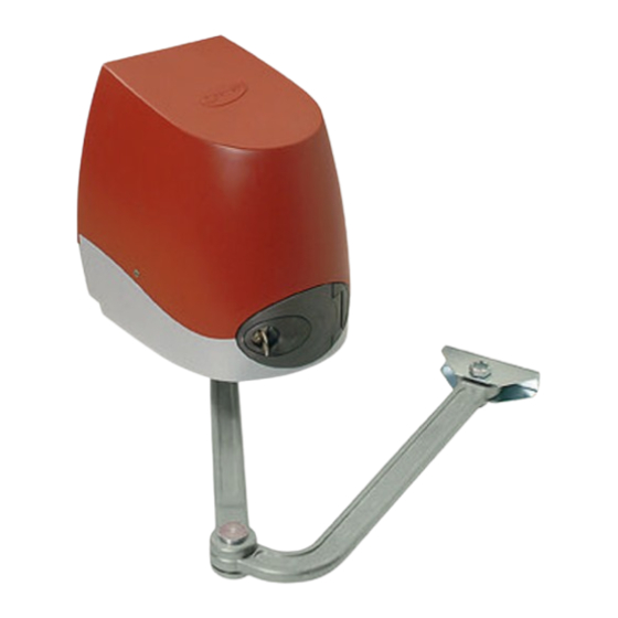
- Page 7 Istruzioni, instructions Fixing the geared motor Unscrew the 4.2x9.5 screws and remove the cover (Fig. 3). Fit the geared motor on the base plate by the holes and lock it in place with the M8x90 screws and nuts (Fig. 4). Figure 3 Figure 4...
- Page 8 Istruzioni, instructions Mounting the articulated arm (Figures 5, 6, 7) 1. the arm must be put in straight by the keyed shaft; position the 11 ∅ x30 washer and lock the arm with the M10x28 screw. 2. Take the curved arm and fit it in the straight arm’s fork; fit the three bushings and the pin and fasten with the 4∅x24 pin.
- Page 9 Istruzioni Instructions Betriebsanleitung Centralina elettronica per motoriduttori elettromeccanici Control board for electromechanical gearmotors Centrale électronique pour motoréducteur électromécanique Elektronische Steuerung für elektromechanische Getriebemotor ULIXES 24V ALPHEO 24V ZEFIRO 24V Rev. 0 - 11/05...
- Page 10 89/392 and norm EN 12453 and EN 12445.. • Use only original parts. Stagnoli do not take any responsibility for damage caused by using unoriginal parts. • Before operating the device, make sure that the power supply has been cut off.
- Page 11 Istruzioni Instructions Betriebsanleitung TECHNICAL SPECIFICATION AND CONNECTION DIAGRAM The electronic control unit for 24V electromechanical gear motors of Stagnoli, is designed for controlling operations of 24 Vdc motors, used for the activation of gates with 1 or 2 leafs; the movement is controlled by the encoder and there is no need to use limit switches.
-
Page 12: Electric Connections
Istruzioni Instructions Betriebsanleitung ELECTRIC CONNECTIONS 1. Neutral power supply from transformer (20Vac) 2. Phase power supply from transformer (20Vac) 3. Battery connection (positive pole). 4. Battery connection (negative pole). 5. Auxiliary output 24Vdc – 500mA (positive pole) 6. Auxiliary output 24Vdc – 500 mA (negative pole ) 7. - Page 13 Istruzioni Instructions Betriebsanleitung at least 1 mm, and should be at least 4 mm from those with low voltage. • The cables used for power supply of motors, should be of at least 2.5 mm and the length should not exceed 10 m; DEFINITIONS OF CONTROL UNIT PARTS F1- FUSE TRANSFORMER INPUT(F10A, 250V): protects the center in case of short circuits or faults that may emerge at the transformer...
- Page 14 Istruzioni Instructions Betriebsanleitung INPUTS/OUTPUTS DEFINITIONS • Input power supply from transformer : 20V~ +/- 10%. • Input/ output accumulators : 2 batteries in series from 12V – 3Ah • Auxiliary output (24V , 500 mA max): used only for feeding safety devices and accessories.
-
Page 15: Functioning Modes
Istruzioni Instructions Betriebsanleitung FUNCTIONING MODES The unit may control various functions based on the combinations of the Dip Switches: FUNCTION ELECTRONIC FRICTION The motor M1 supplies the The motor M1 supplies SW – 1 maximum thrust. the minimum thrust. ELECTRONIC FRICTION The motor M2 supplies the The motor M1 supplies SW –... - Page 16 Istruzioni Instructions Betriebsanleitung NOTE 1. In order to secure always the safety of the automation and to enable the proper carrying out of the programming operation, it is necessary to use the mechanical positive stops at the end of the gate’s course ( in opening and in closing). 2.
Need help?
Do you have a question about the ALPEHO 230 and is the answer not in the manual?
Questions and answers