Advertisement
Quick Links
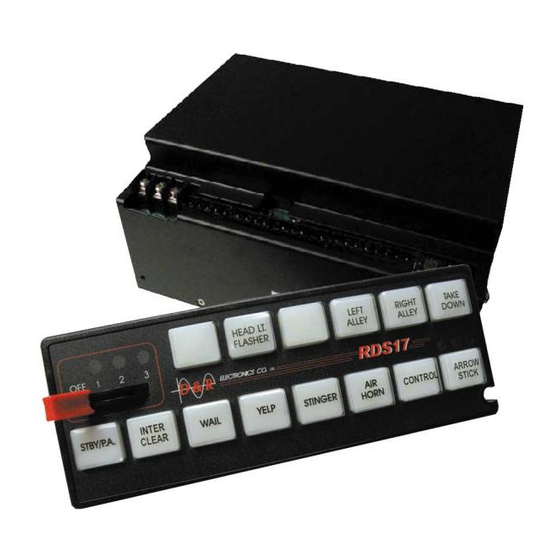
Model: RDS17S
Part#:212-0042
MANUAL RDS17S
LIGHT AND SIREN CONTROL SYSTEM
Unpacking ........................................................................
Description ......................................................................
Installation ........................................................................
Safety ..................................................................
Mounting .............................................................
Wiring ............................................
Operating Instructions .................................................. 6
Standard Features ............................................ 6
Operation ........................................................ 6
Programming .....................................................7
RDS Push Button Label Installation Instruction
Vehicle Boosting ............................................... 12
RDS Packing Lists.......................................
Service and Maintenance ............................................ 14
Troubleshooting ................................................ 14
Specifications ....................................................15
Contents
1
2
2
2
2
3
3
11
13
July 31, 2019
Advertisement

Related Manuals for D&R ELECTRONICS RDS17S

Summary of Contents for D&R ELECTRONICS RDS17S
-
Page 1: Table Of Contents
MANUAL RDS17S LIGHT AND SIREN CONTROL SYSTEM Model: RDS17S Contents Unpacking ................ Description ..............Installation ................ Safety ..............Mounting ............. Wiring ..........Operating Instructions ..........6 Standard Features ..........6 Operation ............6 Programming .............7 RDS Push Button Label Installation Instruction Vehicle Boosting .......... -
Page 2: Installation
Installation Safety Installer Qualifications For proper installation of this product: you must have a good understanding of automotive electr vehicle sound, lighting and warning equipment. Figure 1 - RDS 17S Wiring Diagram Part#: 212-0042 July 31, 2019... - Page 3 Part#:212-0042 July 31, 2019...
- Page 4 Touch pad The RDS17S is a remote keypad model, this allows for the installation of the siren “main box” in an remote location. This is useful when the space in a vehicle’s console does not permit the mounting of the whole siren and touch pad combination.
-
Page 5: Operating Instructions
Operating Instructions Standard Features: The following are standard for the RDS17S, along with the features covered in the previous section of this manual. Adjustable Touch Pad Backlighting – Activated by the ignition, the touchpad buttons have LED’s to light every button. - Page 6 SPECIAL NOTE: Output 9 is a relay contact that can be used for different control functions, Check J5 on the RDS17S Main Relay Box, and set the jumper to provide the correct output polarity or function when SW8 is pressed. Use the wiring diagram on page 4&5 to help set this up.
- Page 7 Program MODE 2 - Using Table 2 1) Enter setup mode Enter by holding SW7+SW8 (see Figure 3) and wait for the 2 beeps 2) Select the program feature you wish to change or set from table 2 3) Change the status (OFF/ON) of SW9 to SW16 to activate the desired function in Table 2. 4) To save the configuration;...
- Page 8 Programming Master Switch SLIDE 1 1) Enter setup mode Enter by holding SW3+SW8 and wait for the 2 beeps Figure 4.1 - Program Master Switch 1 2) Select which switches will be ON with Master. 3) Save the configuration; press and hold SW9 (STBY/PA) until the long beep, this confirms the program is saved.
- Page 9 Using SW16 the following patterns can be activated: LEFT ARROW, RIGHT ARROW, CENTER OUT, CENTER FLASH, ALTERNATE LEFT-RIGHT, RANDOM FLASH. 911 system - in this mode the RDS17S uses OUT13 and OUT14 for traffic director control. Using SW16 the following functions can be activated: LEFT ARROW (OUT13), RIGHT ARROW (OUT 14), CENTER OUT (OUT13 &...
- Page 10 - reconnect the keypad data pigtail to the extension cable and release the STBY/PA switch after the unit makes a long beep (aprox. 2 sec.) The system is reset to factory default. RDS17S PUSH BUTTON LABEL INSTALLATION INSTRUCTION - Remove the Slide Switch red knob. - Depress the locking tab on each end to separate the front and back covers.
- Page 11 SCREW 10-32 X 3/8 401-0007 WASHER #10 ZINC 401-0010 LOCK WASHER #10 ZINC 811-0037A SIREN MOUNTING BRACKET RDS17S RDS17S SYSTEM 212-0042 RDS17S INSTALLATION MANUAL 216-0014 TOUCHPAD LABEL SHEET 211-0008 PACKING BOX 813-0016A REMOTE TOUCH PAD MNT BRKT 813-0017A RDS TP MTG BKT 401-0155...
-
Page 12: Service And Maintenance
Service and Maintenance Troubleshooting PROBLEM POSSIBLE CAUSE PROBABLE SOLUTION System runs properly but shuts down Vehicle battery is low on Recharge vehicle battery or use outputs when heavy outputs are turned on. charge. Bad wiring when vehicle is running and check the car wiring. -
Page 13: Specifications
Specifications General Input Voltage ........11 to 16 Volts DC Input Fuse ........60 Amps (external) Operating Temperature Ranges ..C to +65 Standby Current ........50mA + 10% Weight ..........8 lbs/ 5 Kg Physical Dimensions Height ......... 2.45” Width ........ - Page 14 NOTES: Part#: 212-0042 July 31, 2019...
- Page 15 Part#:212-0042 July 31, 2019...
- Page 16 WARRANTY D & R Electronics warrants its new products to be free from defects in material and workman- ship, under normal use and service for a period of one year on parts replacement. This warranty applies only to original purchasers acquiring the product directly from D&R Electronics, or its authorized dealers.
Need help?
Do you have a question about the RDS17S and is the answer not in the manual?
Questions and answers