
Related Manuals for ITW Dynatec DYNAMINI 4-HOSE


Summary of Contents for ITW Dynatec DYNAMINI 4-HOSE
- Page 1 Adhesive Application Solutions | ISO 9001 certified DYNAMINI 4-HOSE ADHESIVE SUPPLY UNIT Software Version 1.05 and up Technical Documentation, No.20-76, Rev.8.16 ITW Dynatec An Illinois Tool Works Company www.itwdynatec.com...
-
Page 2: Information About This Manual
Please be sure to include the serial number of your application system each time you order replacement parts and/or supplies. This will enable us to send you the correct items that you need. ITW Dynatec Service Parts Direct Dial: 1-800-538-9540 ITW Dynatec Technical Service Direct Dial: 1-800-654-6711 Page 2... -
Page 3: Table Of Contents
Residual Risks ........................17 Technical changes ........................18 Using foreign components ...................... 18 Setting-up operation ........................ 18 3.2 Description Dynamini 4-Hose ............... 19 Specifications .......................... 21 Dimensions..........................22 Chapter 4 Installation & Setting-up Operation ....23 4.1 Conditions for set-up and mounting .............. 23 4.2 Installation .................... - Page 4 Chapter 9 Available Options & Accessories ......71 Pressure Gauge Kit: PN 101175 ..................... 71 Filter Option: ..........................71 Pump Options and Accessories: ..................... 71 Piston Pump Rebuild Kit: PN 109969 ..................71 Page 4 Dynamini 4-Hose, Manual #20-76, Rev. 8.16...
- Page 5 Pneumatic Accessories ......................86 Chapter 11 System Schematics & Engineering Drawings . 87 Hose Schematic, PN 101082, Rev.G ..................87 Head Schematic, PN 103117, Rev.B ..................88 Wiring Diagram 150064 ......................89 Dynamini 4-Hose, Manual #20-76, Rev. 8.16 Page 5...
- Page 6 ITW Dynatec Index This page intentionally left blank. Page 6 Dynamini 4-Hose, Manual #20-76, Rev. 8.16...
-
Page 7: Chapter 1 Declaration Of Incorporation / Conformity
Chapter 1 ITW Dynatec Declaration of Incorporation / Conformity Chapter 1 Declaration of Incorporation / Conformity Dynamini 4-Hose, Manual #20-76, Rev. 8.16 Page 7... - Page 8 ITW Dynatec Chapter 1 Declaration of Incorporation / Conformity This page intentionally left blank. Page 8 Dynamini 4-Hose, Manual #20-76, Rev. 8.16...
-
Page 9: Chapter 2 Safety Instructions
2. Do not remove or deface any of the warning labels, signs and caution statements on the equipment. 3. Replace any warning labels, signs and caution statements which have been removed or defaced. Replacements are available from ITW Dynatec. Dynamini 4-Hose, Manual #20-76, Rev. 8.16 Page 9... -
Page 10: Safety Symbols In This Manual
9. Use the unit only as it is intended to. 10. Never let the unit run unattended. 11. Operate the unit only in a faultless and fully functional condition. Check and make sure that all safety devices work in proper form! Page 10 Dynamini 4-Hose, Manual #20-76, Rev. 8.16... -
Page 11: Explosion/ Fire Hazard
1. PUR adhesives emit fumes (MDI and TDI) that can be dangerous to anyone exposed to them. These fumes cannot be detected by the sense of smell. ITW Dynatec strongly recommends that a power‐vented exhaust hood or system be installed over any PUR system. -
Page 12: Electrical
1. Severe burns can occur if unprotected skin comes in contact with molten adhesive or hot application system parts. 2. Face shields (preferred) or safety glasses (for minimum protection), heat-resistant protective gloves and long-sleeved clothing must be worn whenever working with or around adhesive application systems. Page 12 Dynamini 4-Hose, Manual #20-76, Rev. 8.16... -
Page 13: High Pressure
For this reason, always wear eye protection and protective clothing. 4. Either of the two High Pressure symbols shown may be used on ITW Dynatec equipment. 5. Keep the given operating pressure. -
Page 14: Servicing, Maintenance
3. Use only lifting devices that are suitable for the weight and the dimensions of the equipment (see drawing of the equipment). 4. The unit has to be transported upright and horizontally! 5. The unit has to cool down to room temperature before packaged and transported. Page 14 Dynamini 4-Hose, Manual #20-76, Rev. 8.16... -
Page 15: Treatment For Burns From Hot Melt Adhesives
Appropriate extinguishing agents: Foam extinguisher, Dry powder, Spray, Carbon dioxide (CO2), Dry sand. For safety reasons not appropriate extinguishing agents: None. Firefighting - burning electrical equipment: Appropriate extinguishing agents: Carbon dioxide (CO2), Dry powder. Dynamini 4-Hose, Manual #20-76, Rev. 8.16 Page 15... -
Page 16: Keep Attention To Environmental Protection Standards
3. These matters have to be caught, kept, transported and disposed in appropriate reservoirs! 4. Dispose these matters according to the international, national and regional regulations. Page 16 Dynamini 4-Hose, Manual #20-76, Rev. 8.16... -
Page 17: Chapter 3 Description And Technical Specs
If the unit is not used in accordance with this regulation, a safe operation cannot be guaranteed. The operator - and not ITW Dynatec - is liable for all personal injury or property damages resulting from unintended use! Intended use includes, that you •... -
Page 18: Technical Changes
Any kind of technical changes having impact to the security or the operational liability of the system should only be done by written agreement of ITW Dynatec. Suchlike changes made without given a corresponding written agreement will lead to immediate exclusion of liability granted by ITW Dynatec for all direct and indirect subsequent damages. -
Page 19: Description Dynamini 4-Hose
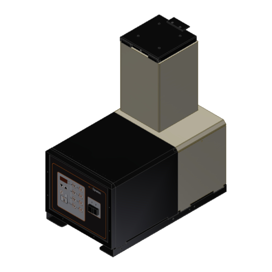
ITW Dynatec Description and Technical Specs 3.2 Description Dynamini 4-Hose The ITW Dynatec’s Dynamini Adhesive Supply Unit (ASU) melts and supplies suitable materials e.g. hot melt adhesives. The Dynamini's teflon‐coated hopper accepts adhesive in all popular forms, including pellets, slugs and blocks. The ASU can accommodate air‐actuated automatic applicators (heads), electric applicators, hand‐held applicators and/or special applicators. - Page 20 ITW Dynatec Chapter 3 Description and Technical Specs Pressure regulator for piston pump DynaControl Electrical and material Main ON/OFF hose connections Power Switch Dynamini 4-Hose ASU Page 20 Dynamini 4-Hose, Manual #20-76, Rev. 8.16...
-
Page 21: Specifications
Operator interface ..............digital display with all-icon keypad Temperature stand-by ........................ yes High & low temperature tolerance ....................yes Ready interlock contact ......................yes Sensor open alarm ........................yes Other CE approval granted ........................yes Dynamini 4-Hose, Manual #20-76, Rev. 8.16 Page 21... -
Page 22: Dimensions
317.32 Model 5 (IN) 13.63 17.75 B+7.25 24.51 12.49 Model 10 (MM) 346.30 B+184 622.56 317.32 Model 10 (IN) 13.63 25.75 B+7.25 24.51 12.49 * All mounting holes are 9.5 mm diameter. Page 22 Dynamini 4-Hose, Manual #20-76, Rev. 8.16... -
Page 23: Chapter 4 Installation & Setting-Up Operation
Advices: • Check all screw connections at the unit and retighten if necessary. • Lay the cables and heated hoses so that no risk or least possible risk of stumbling occurs. Dynamini 4-Hose, Manual #20-76, Rev. 8.16 Page 23... -
Page 24: Installation
The information plate on the ASU will indicate the required power supply. CAUTION Grounding conductors never carry electrical current. The use of a neutral conducting wire as earth ground is incorrect and may cause damage to the controller. Page 24 Dynamini 4-Hose, Manual #20-76, Rev. 8.16... - Page 25 1 PH 230V AC 1 PH + N 230V AC 3 PH 230V AC DELTA 3 PH 230/400V AC WYE Art. Nr. 110763 Art. Nr. 110764 Art. Nr. 110765 Art. Nr. 110766 Dynamini 4-Hose, Manual #20-76, Rev. 8.16 Page 25...
- Page 26 Wattage Available for Wattage Wattage All Hoses and Heads 200-240 VAC 6800 W 1200 W 5600 W 9. Interconnect the components with the foreseen Profibus (or EtherNet, etc.) interface cables (if applicable). Page 26 Dynamini 4-Hose, Manual #20-76, Rev. 8.16...
- Page 27 Chapter 4 ITW Dynatec Installation & Setting-up Operation Rear Cover: Hose and Head Electrical and Adhesive Connections Dynamini 4-Hose, Manual #20-76, Rev. 8.16 Page 27...
-
Page 28: Quality Of Compressed Air
Classification of Quality Classes According to ISO 8573-1: Class 1. Particulate Material 2. Water Content 3. Oil Content max. particle size max. particle density max. pressure dew point max. oil concentration (μm) (mg/m3) (°C) (mg/m3) 0,01 not defined Page 28 Dynamini 4-Hose, Manual #20-76, Rev. 8.16... -
Page 29: Advices For The Setting-Up Operation
ITW Dynatec takes no responsibility for damages or faults caused by any untrained personal. Allow only skilled expert staff to do the setting-up operation! Always wear safety shoes, heat-resistant protective gloves, safety goggles and protective clothing when working on or with the unit. -
Page 30: Setting-Up Operation, In General
If a different adhesive formulation from the one being currently used is needed, the system will have to be flushed if the two formulations are incompatible. See Chapter 6 for the proper flushing procedure. When in doubt about adhesive compatibility, flush your system. Page 30 Dynamini 4-Hose, Manual #20-76, Rev. 8.16... - Page 31 • all temperatures are within the tolerances, and • the adhesive in the ASU hopper is molten completely. NOTE: When the ASU leaves the ITW Dynatec factory, it is programmed with the following factory settings (unless special factory settings were requested): •...
-
Page 32: Shut Down Procedure
4. Remove all air and adhesive supply hoses and all power supply cables. 5. Dismantle all components and sort into mechanical and electrical components. 6. Arrange for all components to be recycled. Page 32 Dynamini 4-Hose, Manual #20-76, Rev. 8.16... -
Page 33: Chapter 5 Controller
A mechanical, redundant thermostat located on the hopper that will turn off the system above safe temperatures. RTD Sensors The system uses 120‐ohm Nickel or 100-ohm Platinum resistance temperature detector (RTD) sensors for all temperature controls. Dynamini 4-Hose, Manual #20-76, Rev. 8.16 Page 33... - Page 34 The firmware chip is on the Control Printed Circuit Board (see Ch. 7). Inscribed on the controller's chip is information that is required if your controller needs service, including the controller's checksum and software revision. Chip example: Firmware chip Software Revision Checksum example Page 34 Dynamini 4-Hose, Manual #20-76, Rev. 8.16...
- Page 35 • Maximum setpoint value: 218°C (425°F). System Values as Programmed by the Factory ITW Dynatec can set the controller's system values to customer's specs, if provided. If customer's specs are not provided, the following values will be entered into the temperature controller at the factory.
- Page 36 ITW Dynatec Chapter 5 Controller 5.2 Controller Programming Instructions Controller Keypad Page 36 Dynamini 4-Hose, Manual #20-76, Rev. 8.16...
- Page 37 This temperature zone is now turned OFF. To turn ON the temperature zone, increase the setpoint. When programming is complete, wait a few seconds and the controller will return to the ASU's actual temperature. Dynamini 4-Hose, Manual #20-76, Rev. 8.16 Page 37...
- Page 38 2. Once the keypad lock is unlocked, programming is possible until the ASU is turned OFF, then back ON or the keypad is locked again. 3. If the keypad must be unlocked permanently, the access code must be de‐activated in the Service Functions. Page 38 Dynamini 4-Hose, Manual #20-76, Rev. 8.16...
- Page 39 2. Press the Service key until you are back to the actual temperatures display, or 3. Press any Hose or Head key and you will return to the actual temperatures screen. Diagram of the Service Functions Loop Dynamini 4-Hose, Manual #20-76, Rev. 8.16 Page 39...
- Page 40 Note: your Tolerance range must be a value between 5 and 50 °F (2 and 27 °C). When Tolerance programming is complete, wait a few seconds and the controller will return to the ASU's actual temperature. Page 40 Dynamini 4-Hose, Manual #20-76, Rev. 8.16...
- Page 41 (in minutes) of delay. 0 = Default, no delay 99 minutes = maximum length of delay When programming is complete, wait a few seconds and the controller will return to the ASU's actual temperature. Dynamini 4-Hose, Manual #20-76, Rev. 8.16 Page 41...
- Page 42 “‐ ‐ ‐" = no Keypad Locking desired numeric value. 1 ‐ 999 = possible Access Code values When programming is complete, wait a few seconds and the controller will return to the ASU's actual temperature. Page 42 Dynamini 4-Hose, Manual #20-76, Rev. 8.16...
- Page 43 The manually programmed setpoint has now been pasted in to all turned on hose and head zones. When programming is complete, wait a few seconds and the controller will return to the ASU's actual temperature. Dynamini 4-Hose, Manual #20-76, Rev. 8.16 Page 43...
- Page 44 ITW Dynatec Chapter 5 Controller Page 44 Dynamini 4-Hose, Manual #20-76, Rev. 8.16...
- Page 45 Maintenance and Repair Notes 6.1 Security advices for maintenance and repair Heed all security advices given in chapter 2. Use only original parts from ITW Dynatec, otherwise ITW Dynatec’s warranty is void! Maintenance and repair work is only permitted for skilled personnel!
- Page 46 Care must be taken not to damage sealing surfaces with sharp objects or sand paper. • Components such as O-rings, fasteners and relief valves should be discarded and replaced by certified ITW Dynatec replacement parts. Re-Assembly Procedures and General Cautions Unless noted, the re-assembly is simply the reverse sequence of the disassembly procedures.
- Page 47 CAUTION Heed all security advices given in chapter 6.1. Use only original parts from ITW Dynatec, otherwise ITW Dynatec’s warranty is void! Please use only the indicated lubricants and keep the prescribed maintenance intervals. Consider in addition the enclosed regulations of manufactures.
- Page 48 Connect the voltage supply and the compressed air supply. Heat the unit up. Wait until all temperatures are within the tolerances and the adhesive in the hopper is molten completely. Continue production. Page 48 Dynamini 4-Hose, Manual #20-76, Rev. 8.16...
- Page 49 9. Replace the filter basket. 10. Apply anti-seize to the threads of the filter nut and re-install. Tighten the filter nut until it is seated firmly, taking care not to cut the O-ring. Dynamini 4-Hose, Manual #20-76, Rev. 8.16 Page 49...
- Page 50 Connect the voltage supply and the compressed air supply. Heat the unit up. Wait until all temperatures are within the tolerances and the adhesive in the hopper is molten completely. Continue production. Page 50 Dynamini 4-Hose, Manual #20-76, Rev. 8.16...
- Page 51 13. Slowly turn the air pressure regulator clockwise. 14. Actuate each applicator until all flushing fluid is removed and a steady stream of new adhesive flows. 15. Re-adjust the pump air pressure for desired flow. 16. Re-fill the hopper. Dynamini 4-Hose, Manual #20-76, Rev. 8.16 Page 51...
- Page 52 Connect the voltage supply and the compressed air supply. Heat the unit up. Wait until all temperatures are within the tolerances and the adhesive in the hopper is molten completely. Continue production. Page 52 Dynamini 4-Hose, Manual #20-76, Rev. 8.16...
- Page 53 5. When unwrapping a PCB from its static drain envelope, place the envelope on a grounded, nonmetallic surface. 6. To cushion a PCB for shipment, use only static‐drain bubble pack. Do not use foam peanuts or bubble pack not known to be static draining. Dynamini 4-Hose, Manual #20-76, Rev. 8.16 Page 53...
- Page 54 3. If an overcurrent occurs on hopper heater(s), its circuit breaker(s) must be reset by 4. Fuses 1 & 2 = 1A, Fuses 3 ‐ 6 = 6.3AF fast. depressing one or both of the round breakers illustrated below. Page 54 Dynamini 4-Hose, Manual #20-76, Rev. 8.16...
- Page 55 ASUs front panel and pressing the reset button in the center of the overtemp switch (note: the reset button is protected by a plastic insulator). Location of Printed Circuit Boards and Overtemp Thermostat Dynamini 4-Hose, Manual #20-76, Rev. 8.16 Page 55...
- Page 56 Resistance in Ohms (240V) Nominal Head Heater Resistance Quantity Heaters Temperature Sensor Resistance Resistance in Ohms for each Heater Nominal Hopper Heater Resistance Note: Resistance is measured at ambient temperature (20°C/ 68°F). Page 56 Dynamini 4-Hose, Manual #20-76, Rev. 8.16...
- Page 57 1. Hopper sensor not fully 1. Check hopper sensor. higher than set-point inserted. (overtemp). 2. Hopper sensor inoperative. 2. Replace hopper sensor if resistance does not comply with resistance table. 3. Inoperative PCB. 3. Replace PCB. Dynamini 4-Hose, Manual #20-76, Rev. 8.16 Page 57...
- Page 58 2. Hose (or Head) fuse on the 2. Insert new fuse. If fuse blows PCB is inoperative. again, check for a short circuit in heater. Note: there are two fuses for each hose /head combination. Page 58 Dynamini 4-Hose, Manual #20-76, Rev. 8.16...
- Page 59 For hose: if sensor is inoperative, replace hose. 2. Short circuit in plug 2. Make proper connection. connection between ASU and Hose (or between Hose and Head). 3. Inoperative PCB. 3. Replace PCB. Dynamini 4-Hose, Manual #20-76, Rev. 8.16 Page 59...
- Page 60 6. Inoperative air cylinder 4- 6. Remove 4-way valve. Inspect, way solenoid valve. clean and repair as necessary. 7. System is not ready. 7. Wait until temperature scale (F/C) light is steady ON (not flashing). Page 60 Dynamini 4-Hose, Manual #20-76, Rev. 8.16...
- Page 61 1. Clean inlet check valve. This Forward-Stroke Only (shaft open. may be possible without moving into pump body). removing the pump by cleaning debris through the pump inlet hole at bottom of hopper. Dynamini 4-Hose, Manual #20-76, Rev. 8.16 Page 61...
- Page 62 1. Filter drain valve not tightly 1. Close and tighten filter drain Spout closed. valve. 2. Filter drain valve blocked 2. Remove filter plug assembly open. from output manifold, clean and re-install. Loosen set screw Open drain Page 62 Dynamini 4-Hose, Manual #20-76, Rev. 8.16...
- Page 63 O- ring grooves or on installation tools that could damage a new seal. 3. Remove pump and inspect bottom of hopper. Repair or replace hopper as necessary. Dynamini 4-Hose, Manual #20-76, Rev. 8.16 Page 63...
- Page 64 ITW Dynatec Chapter 7 Troubleshooting Page 64 Dynamini 4-Hose, Manual #20-76, Rev. 8.16...
- Page 65 CAUTION: HOT-MELT RESIDUE must be cleaned from parts before they are re- assembled, particularly from threaded parts. As a precaution against adhesive residue preventing proper re-assembly, threaded parts must be re-tightened at operating temperature. Dynamini 4-Hose, Manual #20-76, Rev. 8.16 Page 65...
- Page 66 The lid seal (O-ring) is located inside the lid base. 1. Remove the old seal, which rests against the top of the hopper. 2. Install the new seal into the groove provided. Page 66 Dynamini 4-Hose, Manual #20-76, Rev. 8.16...
- Page 67 2. Slip the sensor out of its adapter. 3. Unplug the sensor wires from pins 1 thru 4 at X4 on the Control PCB (see PCB illustration in Chapter 7). Dynamini 4-Hose, Manual #20-76, Rev. 8.16 Page 67...
- Page 68 To remove the following components, remove the face plate of the control panel enclosure only. Printed Circuit Board Fuse Replacement: Note: Use replacement fuses of the same type. If in doubt, obtain the correct fuses from ITW Dynatec. 1. Locate desired fuse by referring to PCB illustration in Chapter 7.
- Page 69 Carefully loosen the purge screw located in the port of the outlet filter manifold and allow adhesive and pressure to escape. See point 6.3 “Purging the Filter Manifold of Adhesive and Pressure” for detailed instructions. Dynamini 4-Hose, Manual #20-76, Rev. 8.16 Page 69...
- Page 70 22.6 Nm (16.7 ft/lb) at room temperature. With pump and hopper at 177°C (350°F), the maximum Piston Pump allowable torque on pump assembly screws is 18.8 Nm (13.9 ft/lb). A Piston Pump Rebuild Kit is available. Page 70 Dynamini 4-Hose, Manual #20-76, Rev. 8.16...
- Page 71 This kit contains a PN 105328 Pump Repair Kit, a PN 109968 Pump & Airmotor Seals Kit, a L16534 Pump Shaft, a L21189 Inlet Check Valve Assembly and a L21188 Outlet Check Valve Assembly. Dynamini 4-Hose, Manual #20-76, Rev. 8.16 Page 71...
- Page 72 Pneumatic Pressure Relief Valve Retrofit Kits: PN 116620 Retrofit Kit for Piston Pump ASUs. ITW Dynatec’s PN 115540 Pneumatic Pressure Relief Valve Assembly (contained in the above kit) automatically relieves adhesive pressure whenever the unit is turned off or when pneumatic air is disconnected. The retrofit kit is detailed in Chapter 10.
- Page 73 Note: Most common nuts, bolts and fasteners can be obtained locally at your hardware store. Specialty fasteners are available by contacting ITW Dynatec’s Customer Service. Dynamini 4-Hose, Manual #20-76, Rev. 8.16...
- Page 74 Cable Assembly, Power Switch (NOT SHOWN) 110748 Cable Assembly, Keypad/ Display 102762 Fuse, 5 x 20, 1.0A, Fast 108566 Fuse, 5 x 20, 6.3A, Time-Delay 111941 Circuit Breaker, 15A * see separate drawing and/or bill of material. Page 74 Dynamini 4-Hose, Manual #20-76, Rev. 8.16...
- Page 75 Chapter 10 ITW Dynatec Component Illustrations and Bill of Materials Illustration: Electrical Panel Assembly Dynamini 4-Hose, Manual #20-76, Rev. 8.16 Page 75...
- Page 76 Seal And Bearing Assembly 115497 1/8 NPT Street Tee Airline Plug (used only on ASUs equipped with N06506 mechanical pressure relief valve) Note: * These items are included in Piston Pump Rebuild Kit 109969 continue… Page 76 Dynamini 4-Hose, Manual #20-76, Rev. 8.16...
- Page 77 Chapter 10 ITW Dynatec Component Illustrations and Bill of Materials Illustration: Piston Pump & Air Motor Assembly PN 105073 (240V) Dynamini 4-Hose, Manual #20-76, Rev. 8.16 Page 77...
- Page 78 Filter/ Regulator Assy N06430 Brass Male Connect Fitting 105113 Screw M4 x 8 SHC 101888 Air Block N01067 Brass Nipple Note: * These items are included in Piston Pump Rebuild Kit 109969 Page 78 Dynamini 4-Hose, Manual #20-76, Rev. 8.16...
- Page 79 Chapter 10 ITW Dynatec Component Illustrations and Bill of Materials Illustration: Piston Pump & Air Motor Assembly PN 105073 (240V) Dynamini 4-Hose, Manual #20-76, Rev. 8.16 Page 79...
- Page 80 Heat Shield 680591 Access Cover 680593 Cover, Hose, Single Filter 680584 Rear Cover End 610133 Bracket Connector, Dynacontrol 680697 Bracket Connector, Nordson (not shown) 665004 Connector, Dynacontrol 665007 Connector, Nordson (not shown) Page 80 Dynamini 4-Hose, Manual #20-76, Rev. 8.16...
- Page 81 Chapter 10 ITW Dynatec Component Illustrations and Bill of Materials Illustration: Cabinet Assembly Dynamini 4-Hose, Manual #20-76, Rev. 8.16 Page 81...
- Page 82 Ceramic Spacer 104530 Aluminum Spacer 106157 Lock Washer, M4, Int. Tooth 105133 Screw, SHC Screw, M4 x 8mm 102998 Heat Transfer Plate, Piston Pump (option) N00688 Flat Washer 803948 M8 x 40 Stud Page 82 Dynamini 4-Hose, Manual #20-76, Rev. 8.16...
- Page 83 Chapter 10 ITW Dynatec Component Illustrations and Bill of Materials Illustration: Drive Section Dynamini 4-Hose, Manual #20-76, Rev. 8.16 Page 83...
- Page 84 Not replaceable Cast-in Heater 103041 Hopper Filter No P/N Nut, M4 No P/N Washer, M4 No P/N Porcelain Spacer 102411 Cap, Hi Temp, .60 ID x 1.5L L07348 Weir, Hopper Illustration: Melt Section Page 84 Dynamini 4-Hose, Manual #20-76, Rev. 8.16...
- Page 85 Fitting, plug, 1/4 BSPP 101833 Screw, tamperproof, 10-32 x 1/2 104852 Drain plug 001U002 Lube, silicone, DOW 112 N08171 Sealant, DOW 732 107324 Anti-seize compound, Chesterton 710 * A/R = As required. Illustration: Filter Manifold Dynamini 4-Hose, Manual #20-76, Rev. 8.16 Page 85...
- Page 86 072X228 Fitting, hex nipple, 1/4 NPT Screw M4x8mm 101888 Block, pneumatic transfer N00101 Fitting 90°, 1/4 tube x 1/4 NPT 072X383 Airline support (not shown) * See detailed drawing on following pages. Page 86 Dynamini 4-Hose, Manual #20-76, Rev. 8.16...
- Page 87 2. Wire sizes shown are for no. 6 and no. 8 hoses up to 24 ft. in length. For larger diameter and longer hoses, heater lead wires are 16 AWG. Other wire sizes and colors may be changed in special hoses, per customer request. Dynamini 4-Hose, Manual #20-76, Rev. 8.16 Page 87...
- Page 88 Head Schematic, PN 103117, Rev.B NOTES: 1. All wire MIL-W-22759/10 or 12, minimum 600 Volts, 260 °C. 2. Solenoid(s) voltage and timing method depends on application. 3. RTD will be platinum 100 Ohm. Page 88 Dynamini 4-Hose, Manual #20-76, Rev. 8.16...
- Page 89 Chapter 11 ITW Dynatec System Schematics & Engineering Drawings Wiring Diagram 150064 Dynamini 4-Hose, Manual #20-76, Rev. 8.16 Page 89...
- Page 90 ITW Dynatec Chapter 11 System Schematics & Engineering Drawings This page intentionally left blank. Page 90 Dynamini 4-Hose, Manual #20-76, Rev. 8.16...
- Page 91 Chapter 11 ITW Dynatec System Schematics & Engineering Drawings This page intentionally left blank. Dynamini 4-Hose, Manual #20-76, Rev. 8.16 Page 91...
- Page 92 28500 Chérisy No.9 Weixin Road 26-11, Nishikamata 7-chome Germany France SIP, Suzhou, 215122 Ota-ku, Tokyo 144-0051, Tel. +1.615.824.3634 Tel. +49.2104.915.0 Tel.: +33.237.62.56.47 China Japan Toll Free +1.800.966.6358 Tel. +86.512.6289.0620 Tel. +81.3.5703.5501 dynatec@itwdynatec.com Page 92 Dynamini 4-Hose, Manual #20-76, Rev. 8.16...
Need help?
Do you have a question about the DYNAMINI 4-HOSE and is the answer not in the manual?
Questions and answers