Table of Contents
Advertisement
Available languages
Available languages
Quick Links
Advertisement
Chapters
Table of Contents

Subscribe to Our Youtube Channel
Related Manuals for Hameg HO79-6


Summary of Contents for Hameg HO79-6
- Page 1 ® Instruments Interface HO79-6 V 3.x MANUAL•HANDBUCH•MANUEL...
-
Page 2: Table Of Contents
CE Konformitätserklärung ................5 Sicherheitshinweise ..................6 Stromversorgung ..................... 6 Umgebungsbedingungen ................6 Garantie ......................6 Beschreibung des Interface HO79-6 ............7 Terminologie ..................... 7 1. Schnittstellen ....................7 1.1 IEEE-488-Schnittstelle (GPIB) ..............7 1.1.1 Hardware konfiguriert ..............7 1.1.2 Software konfiguriert ..............7 1.2 Device-Betrieb .................. - Page 3 10.1 RS-232 ....................28 10.2 GPIB ....................28 Manual HO79-6 English ..........Anhang(Appendix): Zeichentabelle (ASCII chart) ........58 Anhang(Appendix): Anschlüsse und Verdrahtung (Connectors and Wiring) ..........59 Anhang(Appendix): Frontansicht HO79-6 (Frontside HO97-6) .... 60 Änderungen vorbehalten / Subject to change without notice...
-
Page 4: Allgemeine Hinweise Zur Ce-Kennzeichnung
HAMEG Meßgeräte erfüllen die Bestimmungen der EMV Richtlinie. Bei der Konformitäts- prüfung werden von HAMEG die gültigen Fachgrund- bzw. Produktnormen zu Grunde gelegt. In Fällen wo unterschiedliche Grenzwerte möglich sind, werden von HAMEG die härteren Prüfbedingungen angewendet. Für die Störaussendung werden die Grenzwerte für den Geschäfts- und Gewerbebereich sowie für Kleinbetriebe angewandt (Klasse 1B). -
Page 5: Ce Konformitätserklärung
® Instruments KONFORMITÄTSERKLÄRUNG DECLARATION OF CONFORMITY DECLARATION DE CONFORMITE Herstellers HAMEG GmbH Manufacturer Kelsterbacherstraße 15-19 Fabricant D - 60528 Frankfurt Bezeichnung / Product name / Designation: Multifunktions Interface/Multifunction-Bus/Interface Multifonctions HO79- Typ / Type / Type: mit / with / avec: HM305-2, HM1507, HM407, HM507... -
Page 6: Sicherheitshinweise
Sicherheitshinweise Ihr HAMEG-Interface HO79-6 wurde gemäß den Bestimmungen VDE 0411 Teil 1, Sicherheitsbestimmungen für elektrische Meß-, Steuer-, Regel- und Laborgeräte, gebaut und geprüft. Damit entspricht es auch den Bestimmungen der europäischen Norm EN61010 bzw. der internationalen Norm IEC 1010-1. Es hat das Werk in sicherheitstech- nisch einwandfreiem Zustand verlassen. -
Page 7: Beschreibung Des Interface Ho79-6
Die nach dem IEEE-488 Standard erlaubten maximalen Kabellängen dürfen nicht überschritten werden. Das IEEE-488-Bus Kabel muß mit einer doppelten Abschirmung versehen sein, so wie dies bei den HAMEG Kabeln HZ72L und HZ72S der Fall ist. 1.1.1 Hardware konfiguriert Ist Schalter SW1 wirksam (nicht durch Softwarekonfiguration überschrieben) und auf Stellung 0, 1, 2 oder 3 geschaltet, kann über den IEEE-488-Bus eine Dokumentation... -
Page 8: Device-Betrieb
1.2 Device-Betrieb In Verbindung mit einem IEEE-488 Controller (PC mit Steckkarte wie z.B. HO80-2 ausgerüstet), kann das Interface HO79-6 und damit das Oszilloskop, im Device-Betrieb zusammen mit anderen Geräten am IEEE-488-Bus betrieben werden. Das Interface kann dabei mit Schalter SW2 auf eine von 14 möglichen Adressen (1 Hex bis E Hex) geschaltet werden und unter dieser Adresse Befehle vom Controller erhalten. -
Page 9: Hardware Konfiguriert
In dieser Betriebsart muß das Interface ermitteln, ob eine Signalaufzeichnung erfolgt ist. Bei jeder Abfrage leuchtet die “RM”-LED des Oszilloskops kurz auf. 1.5 PRINTER (CENTRONICS) -Schnittstelle Nicht für HAMEG Graphic-Printer! Über die Printer-Schnittstelle können Daten parallel nur zur Dokumentation an Geräte mit CENTRONICS-Anschluß (z.B. Drucker) gesendet werden; d.h. die Schnittstelle wirkt unidirektional. -
Page 10: Hardware Konfiguriert
Wie im Abschnitt „Software“ erläutert, empfängt und sendet das Interface HO79-6 Befehle nach dem SCPI-Standard. Die serielle Schnittstelle des Oszilloskops ist nach der Befestigung des Interface HO79-6 am Oszilloskop nicht mehr zugänglich. Der RS-232 Durchschleif-Betrieb ermöglicht es, das Oszilloskop mit einer Software zu betreiben, die den Befehlssatz des Oszilloskops benutzt. -
Page 11: Ausgabeformat- Und Schnittstellen-Einstellung
HPGL (für HPGL-Plotter und -Drucker) PCL (für PCL Tintenstrahl- und Laserdrucker mit mindestens 300dpi Auflösung) EPSON (für Matrixdrucker mit 9 oder 24 Nadeln) 2.1 Ausgabeformat- und Schnittstellen-Einstellung Mit SW1 werden Schnittstelle und Ausgabeformat (Sprache) bestimmt: 0: IEEE, Post Script 1: IEEE, HPGL 2: IEEE, PCL 3: IEEE, EPSON 4: RS-232, Post Script... -
Page 12: Printer-Betrieb
(Schutzleiter mit Gehäuse und allen Meßanschlüssen verbunden). Sollte dies nicht der Fall sein, darf die Installation nicht erfolgen. Setzen Sie sich in diesem Falle bitte mit HAMEG in Verbindung! 4.1 Oszilloskop ausschalten und Netzstecker ziehen. 4.2 Das Oszilloskop mit der Frontseite auf eine weiche Unterlage stellen und darauf achten, daß... -
Page 13: Inbetriebnahme
4.3 Die rechts von der 9poligen D-Sub Buchse befindliche und die unterhalb der Netzsteckerbuchse befindliche Hutmutter abschrauben. Achtung! Ein Teil der Anlog-/Digital-Oszilloskope HM305-2 und HM1507 ist nicht mit einer Hutmutter unterhalb der Netzsteckerbuchse ausgerüstet. Dem Interface sind die erforderlichen Teile beigepackt, um diesen Befestigungspunkt nach- rüsten zu können. -
Page 14: Mechanische Betriebsparametereinstellung
CENTRONICS, RS-232 und GPIB (IEEE-488). 5.2.2.3 HEADER (Kopfzeile): HEADER ON (Ein), HEADER OFF (Aus) und BORDER ONLY (wie HEADER ON, aber nur die Außenkontur des HAMEG Logo wird gedruckt bzw. geplottet). 5.2.2.4 SETUP (Oszilloskop-Einstellungen): SETUP ON (Ein = Dokumentation) und SETUP OFF (undokumentiert). -
Page 15: Auslösen Der Dokumentation
Defaultwert für IEEE-488 (GPIB) die Adresse “1” ist, also nicht “Talk Only” (SW2=0). 6. Software Das Interface HO79-6 empfängt Befehle in der Programmiersprache SCPI; diese Abkürzung steht für “Standard Commands for Programmable Instruments” (Standard Befehle für programmierbare Test- und Meßgeräte). Dieser Standard wird auch von anderen Meßgeräteherstellern benutzt und bedeutet daher eine wesentliche Erleichte-... -
Page 16: Verwendete Zeichen Und Klammern
Die in der Befehlsbeschreibung verwendeten Zeichen und Klammer haben folgende Be- deutung: 6.3 Oszilloskop-Parameter Datenaktualisierung Beim Einschalten des Oszilloskops übernimmt das Interface HO79-6 alle Parameter vom Oszilloskop, für die es SCPI Befehle gibt (Parameterbefehle); sie sind unter 7.2 INPut, 7.3 SENSe, 7.4 SELect und 7.5 TRIGger aufgeführt. Die diesbezüglichen Kommandoerläute- rungen sind unter 8.2 INPut, 8.3 SENSe, 8.4 SELect und 8.5 TRIGger zu finden. -
Page 17: Sense
:POSition <f | MAXimum | MINimum> 7.3 SENSe :AVERage <OFF | ON> :COUNt <f | MAXimum | MINimum> :TYPE <ENVelope | SCAlar> :SWEep [:TIME] <f | MAXimum | MINimum> [S] :GENeration <STEPped | ANALog> :VOLTage [:DC] [:RANGe] [:PTPeak] <f | MAXimum | MINimum> [V] [:RANGe] [:PTPeak] <f | MAXimum | MINimum>... -
Page 18: Header
7.8 HEADer <OFF | ON> 7.9 SYSTem :VERSion :ERRor :ELISt :UPDate :SERial : BAUD <f | MAXimum | MINimum> : GPIB : ADDress <f | MAXimum | MINimum> 7.10 IEEE 488.2 entsprechende Befehle (Beschreibung unter Punkt 9) *CLS *ESE *ESR *IDN *OPC *RST... -
Page 19: Input Subsystem
Parameter: ASCii, BINary, HEXadecimal, INTeger, UINTeger, OCTal *RST Wert: ASCii Beispiel: „:form int,16;“ // wählt „short integer“ als Datenformat. „:form uint,32;“ // schaltet auf das Datenformat „unsigned long integer“. 8.1.2 :FORMat:BORDer < NORMal | SWAPped> FORMat:BORDer; :FORMat:BORDer < NORMal | SWAPped> FORMat:BORDer?; Beschreibung: Die Byte ORDer Einstellungen wirken nur auf die Parameter des Subsystems „Trace“... - Page 20 Beschreibung: Schaltet die Mittelwertbildung (AVERAGE) am Oszilloskop ein oder aus. Siehe auch Oszilloskop-Bedienungsanleitung. Anwendung: Befehl, Abfrage. Parameter: ON, OFF. *RST Wert: nicht anwendbar (bedingt durch Oszilloskop) 8.3.2 :SENSe:AVERrage:COUNt <f | MAXimum | MINimum>; :SENSe:AVERrage:COUNt [MAXimum | MINimum] ?; Beschreibung: Setzt oder fragt ab, mit welchem Anteil jede einzelne Signalerfassung in die Mittelwertbildung eingeht (Auflösung).
-
Page 21: Select Subsystem
reich für den zweiten Kanal zu setzen bzw. abzufragen, muß VOLTage um die Ziffer 2 ergänzt werden. Parameter ist eine Fließkommazahl, die durch eine optionelle Einheiten- angabe (V, mV, µV, ...) ergänzt werden kann, bzw. durch MAXimum oder MINimum. Letzeres bewirkt, daß der größte oder kleinste Ablenkkoeffizient gewählt bzw. -
Page 22: Trace Subsystem
Eine Liste der gültigen Namen läßt sich mit TRAce:CATalog abrufen. Das empfangene Datenformat wird mit dem Subsystem „Format“ eingestellt. Wie bei allen HAMEG Oszilloskopen, beträgt die Wertigkeit der Daten 25 Bit/Div. Die Anzahl der Daten entspricht der Speichertiefe des Kanals. -
Page 23: Hcopy Subsystem
8.6.2 :TRAce:CATalog?; Beschreibung: Auf diese Abfrage wird mit einer durch Kommas getrennten Zeichenfolge geantwortet, welche alle Strahlnamen enthält. Anwendung: Abfrage. 8.6.3 :TRAce:COPY<trace_name>,<trace_name>; Beschreibung:Mit diesem Befehl lassen sich Signaldaten von Kanal 1 oder 2 in einen Referenzspeicher kopieren. Es kann auch innerhalb der Referenzspeicher kopiert werden. - Page 24 8.7.7 :HCOPy:HEADer <OFF | ON | BORDer >; :HCOPy:HEADer ?; Beschreibung:Mit diesen Befehlen kann das Ausdrucken der Kopfzeile ein- oder abgeschaltet werden. BORDer bewirkt, daß nur die Außenkontur des HAMEG-Logo gedruckt/geplottet wird. Anwendung: Befehl, Abfrage. Parameter: OFF, ON *RST Wert: 8.7.8 :HCOPy:SETUp <OFF | ON>;...
-
Page 25: Header Subsystem
8.7.11 :HCOPy:EDGEs <OFF | ON>; :HCOPy:EDGEs ?; Beschreibung:Schaltet den Ausdruck von vier Symbolen ein oder aus, mit denen der Platzbedarf für einen Ausdruck angezeigt wird. Anwendung: Befehl, Abfrage. Parameter: OFF, ON *RST Wert: OFF. 8.7.12 :HCOPy:COLor <OFF | ON>; :HCOPy:COLor ?; Beschreibung: Schaltet die Farbe im Ausdruck aus oder an. -
Page 26: Ieee 488.2 Entsprechende Befehle
auf der Fehlerliste gelöscht. Die nächste Abfrage zeigt den nächsten Feh- ler an, wenn ein Fehler vorhanden war. Anwendung: Abfrage. Parameter: keine. 8.9.3 :SYSTem:ELISt?; Beschreibung: Diese Abfrage ist eine Erweiterung von „:SYSTem:ERRor?;“. Die Abfrage bewirkt die Anzeige einer Fehlerliste, die - falls vorhanden - mehrere Fehler gleichzeitig anzeigt und gleichzeitig auf der Fehlerliste löscht. - Page 27 *IDN? Beschreibung: Identifikations-Abfrage. Die Antwort auf *IDN? identifiziert ein einzelnes Gerät und besteht aus einer Zeichenfolge, die sich aus vier Datenfeldern zusammensetzt, die durch Komma getrennt sind. Die Bedeutung der Datenfelder lautet: <Hersteller>,<Type>,<Seriennummer>,<Version>. <Version> ist un- terteilt in <Interfaceversion (Hardware) Oszilloskopversion (Software)>. Anwendung: Abfrage.
-
Page 28: Anwendung Der Scpi Befehle
Sie können über die GPIB-Schnittstelle oder über die RS-232 zum HO79 gesendet werden. 10.1 RS-232 Es wird davon ausgegangen, daß HO79-6 über ein 1:1 Kabel (d.h. OHNE Leitungskreuzun- gen) mit dem PC verbunden und eine Windowsversion mit installierten HyperTerminal vorhanden ist. - Page 29 falls mit installiert. Im Folgenden ist ein kleines Script aufgelistet, um den Einstieg zu erleichtern. Die Interruptnummer der GPIB-Karte erfahren Sie aus dem Windows-Gerätemanager. Markieren Sie die GPIB-Karte und klicken Sie auf „Eigenschaften“. Wählen Sie dann die Karteikarte „Ressourcen“. Script: init 704, 0, 3, 0 set #1, 1000, 1010, 1010 remote #1...
- Page 30 Änderungen vorbehalten / Subject to change without notice...
-
Page 31: Manual Ho79-6 English
® Instruments Instruments Instruments Instruments Instruments Interface HO79-6 V 3.x Änderungen vorbehalten / Subject to change without notice... - Page 32 General information regarding the CE marking ........34 CE Declaration of Conformity ..............35 Safety Instructions ..................36 Environmental conditions ................36 Warranty ......................36 Terminology ....................37 1. Ports and Modes ..................37 1.1 IEEE-488- (GPIB) Port ................37 1.1.1 Hardware configuration ...............
- Page 33 Table of contents 4. Installation ....................42 5. Putting into Operation ................43 5.1 Mechanical Operating Parameters Setting ........43 5.2 Electronic Operating Parameters Setting .......... 43 5.2.3 Starting the Documentation ............. 44 6. Software ...................... 44 6.1 Command Structure ................44 6.2 Symbols and Brackets .................
-
Page 34: General Information Regarding The Ce Marking
General information regarding the CE marking HAMEG instruments fulfill the regulations of the EMC directive. The conformity test made by HAMEG is based on the actual generic- and product standards. In cases where different limit values are applicable, HAMEG applies the severer standard. For emission the limits for residential, commercial and light industry are applied. -
Page 35: Ce Declaration Of Conformity
® Instruments KONFORMITÄTSERKLÄRUNG DECLARATION OF CONFORMITY DECLARATION DE CONFORMITE Herstellers HAMEG GmbH Manufacturer Kelsterbacherstraße 15-19 Fabricant D - 60528 Frankfurt Bezeichnung / Product name / Designation: Multifunktions Interface/Multifunction-Bus/Interface Multifonctions HO79- Typ / Type / Type: mit / with / avec: HM305-2, HM1507, HM407, HM507... -
Page 36: Safety Instructions
IEC 1010-1 and European EN 61010 regulations. It has left the factory in optimal condition regarding safe operation. To maintain this condition and to ensure danger-free operation, the user of the HO79-6 must adhere to the indications and warnings made in this manual. -
Page 37: Terminology
(RS-232) interface is included in the oscilloscope manual. In digital mode the HO79-6 enables the output (documentation) and the reception (reference signals) of signal data. In addition the instrument can be controlled via the interface in analog and digital mode. -
Page 38: Talk-Only Mode
1.3 Talk-Only mode In this mode IEEE-488 devices can be used for documentation, which are set to ”listen only” mode. In that case an IEEE-488 controller is not required. There are two types of documentation in ”talk only” mode: 1.3.1 Manually started documentation in ”talk only” mode Prerequisite switch SW1 is in position ”0, 1, 2 or 3”... -
Page 39: Baudrate Setting
In this mode the interface has to detect the presence of a completed recording. Each query causes the “RM“-LED to light. 1.5 PRINTER- (CENTRONICS) Port Not for HAMEG Graphic-Printer! This unidirectional port enables byte-serial data transmission for documentation by devices (e.g. printer) which are equipped with a CENTRONICS connector. Data transfer in the sense of the terminology used in this description cannot be performed via this port. -
Page 40: Rs-232 Connect Through Mode
“RM“-LED to light. 1.6 RS-232 connect through mode As mentioned in section ”software”, the interface HO79-6 receives and transmits commands defined in the SCPI standard. After mounting the interface at the rear of the scope, the scope RS-232 connector is not accessible. -
Page 41: Rs-232 Mode
0: ”Talk only” mode (manually or command controlled) 1: ”Device” mode under address 1 2: ” ” ” ” 3: ” ” ” ” 4: ” ” ” ” 5: ” ” ” ” 6: ” ” ” ” 7: ” ”... -
Page 42: Installation
Please check first that the oscilloscope corresponds to the SAFETY CLASS I conditions (three-conductor power cord with protective earthing contacts on plugs and oscilloscope). If not, it is not permitted to install the interface. In this case contact your HAMEG distributor. -
Page 43: Putting Into Operation
(see appendix), and switch the oscilloscope on again after a minimum time of 10 seconds. 5.2 Electronic Operating Parameters Setting The following description notes the differences, if the HAMEG Oscilloscope is supplied with a pushbutton marked ”PRINT”: 5.2.1 After the instrument is switched ON and the self test has passed, ”HO79 DETECTED”... -
Page 44: Starting The Documentation
488 (GPIB) range is ”Address = 1” and not as required in this case ”Talk Only” (SW2 = 0). 6. Software The interface HO79-6 receives commands defined in the SCPI standard (Standard Commands for Programmable Instruments). As this standard is also used by other instrument manufacturers, the use of SCPI eases programming of customer specific programs and is therefore recommended. -
Page 45: Symbols And Brackets
e.g.: “:select:catalog ?;“ or “:sel:cat ?;“ Both types are acceptable. 6.2 Symbols and Brackets The symbols and brackets used in the command description have the following meaning: 6.3 Oscilloscope Parameter Update The oscilloscope parameters for which SCPI commands (parameter commands) exist are taken over by the interface when the interface (oscilloscope) is switched on;... -
Page 46: Scpi Command Tree
7. SCPI Command Tree Given below is the SCPI command tree for the HO79-6 interface. Please note item 8 for a detailed description. 7.1 FORMat [:DATA] <ASCii | BINary | HEXadecimal | INTeger | UINTeger | OCTal>[,<f>] :BORDer <NORMal | SWAPped>... -
Page 47: Command Descriptions
7.7 HCOPy [:IMMediate] :ABORt :LANGuage <PCL | HPGL | EPSon | POSTscript | PCX> :STArt (<block> | <numeric_values>) :END (<block> | <numeric_values>) :PORt <CENTronics | RS-232 | GPIB | SOURce> :HEADer <OFF | ON | BORDer> :SETUp <OFF | ON> :TEXT <OFF | ON>... -
Page 48: Input Subsystem
The following argument specifies the number of digits (ASCii, BINary, HEXadecimal, OCTal) or the number of bits (INTeger, UINTeger). ASCii: data is transferred as <NR1> format separated by commas. BINary: data is encoded with base 2, preceded by “#B“. OCTal: data is encoded with base 8, preceded by “#Q“. HEXadecimal: data is encoded with base 16, preceded by “#H“. -
Page 49: Sense Subsystem
Description: Sets or returns the input (ground line-)position. The value is given in divisions. A 0 means the middle of the screen. Forms: Command and query. *RST Value: N/A Examples: ":inp:pos -4;" (set groundline to screen bottom) ":inp:pos2 2;" (set groundline of ch2 to the 90%-line) 8.3 SENSe Subsystem 8.3.1 :SENSe:AVERage <ON | OFF>;... -
Page 50: Select Subsystem
8.3.5 :SENSe:SWEep:GENeration <STEPped | ANALog>; :SENSe:SWEep:GENeration ?; Description: Sets or returns the signal display regarding the signal recording mode. “STEPped“ stands for digital and “ANALog“ for analog mode. Forms: Command and query. Parameters: STEPped, ANALog. *RST Value: N/A. 8.3.6 :SENSe:VOLTage] <f | MAXimum | MINimum> [V]; :SENSe:VOLTage] <f | MAXimum | MINimum>... - Page 51 Forms: Command. Parameters: None. 8.5.2 :TRIGger:DELay:AUTO <OFF | ON | ONCE>; :TRIGger:DELay:AUTO ?; Description: Set the trigger to auto norm or single mode. Forms: Command and query. *RST Value: N/A. 8.5.3 :TRIGger:FILTer <OFF | HF | NR | LF | TVL | TVF>; :TRIGger:FILTer ?;...
-
Page 52: Trace Subsystem
Examples: “:trigger:level 1300 mv;“ // sets the trigger level to 1.3V. “:TRIG:LEV MAX ?; // query for trigger level. 8.6 Trace Subsystem8.6 Trace Subsystem 8.6.1 :TRAce[:DATA] <trace_name>?; Description: Returns “trace“ (channel, reference signal) signal data. Valid trace names are returned from a TRAce:CATalog command. The format of the received data can be determined by “:FORMat[:Data] <... - Page 53 8.7.7 :HCOPy:HEADer <OFF | ON | BORDer>; :HCOPy:HEADer ?; Description: These commands can be used to select between printing/plotting the header or not. If BORDER was selected, only the outline of the HAMEG Logo is printed / plotted. Forms: Command and query.
-
Page 54: Header Subsystem
8.7.10 :HCOPy:GRATicule <OFF | ON>; :HCOPy: GRATicule ?; Description: This command can switch off the printing of the raster. Forms: Command and query. Parameters: OFF, ON. *RST Value: ON. Remark: Replaces RASTer. 8.7.11 :HCOPy:EDGEs <OFF | ON>; :HCOPy:EDGEs ?; Description: This command can switch on the printing of 4 little edges to show outline of the printing. -
Page 55: Ieee 488.2 Compliant Commands
Forms: Query. Parameters: None. 8.9.2 :SYSTem:ERRor?; Description: This query is used to obtain a description of the error encountered while the command parser processed the previous commands. The response is an error number followed by a description. If there was no error in the previous commands, this query responds with 0,“No errors“. - Page 56 Forms: Command and query. Parameters: None. *ESR? Description: Standard Event Status Register Query. Reading this register clears it. This register is defined in IEEE-488 11.5.1.2. Forms: Query only. Parameters: None. *IDN? Description: Identification Query. The response from *IDN? identifies a unique instrument.
-
Page 57: Application Of Scpi Commands
They can be transmitted to the interface HO79-6 via the GPIB or the RS- 232 connector. 10.1 RS-232 It is assumed that HO79-6 is connected via a 1:1 cable (no line crossovers) to a PC with a windows version that includes “HyperTerminal“. HO79-6 Settings: SW1: RS-232;... -
Page 58: Anhang(Appendix): Zeichentabelle (Ascii Chart)
HO79 Settings: SW1: Any Setting SW2: Instrument Address; Setting 1 to E; e.g. setting 4 selects address 4. Wali32 The program “Wali32.exe“ is a terminal program which is part of the HO80 and HO82 delivery. After installation it enables to write a script and let it run. A help file with command and syntax description is also available after installation. -
Page 59: (Connectors And Wiring)
Anhang: Zeichentabelle Appendix: ASCII chart ASCII & IEEE (GPIB) CHART Änderungen vorbehalten / Subject to change without notice... -
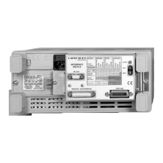
Page 60: Anhang(Appendix): Frontansicht Ho79-6 (Frontside Ho97-6)
Anhang: Anschlüsse und Verdrahtung Appendix: Connectors and Wiring Änderungen vorbehalten / Subject to change without notice... -
Page 61: Appendix: Frontside Ho97-6
Anhang: Frontansicht HO79-6 Appendix: Frontside HO97-6 Änderungen vorbehalten / Subject to change without notice... - Page 64 ® Germany HAMEG Service Kelsterbacher Str. 15-19 Instruments 60528 FRANKFURT am Main Tel. (069) 67805 - 24 -15 Telefax (069) 67805 - 31 E-mail: service@hameg.de Oscilloscopes HAMEG GmbH Industriestraße 6 63533 Mainhausen Multimeters Tel. (06182) 8909 - 0 Telefax (06182)
Need help?
Do you have a question about the HO79-6 and is the answer not in the manual?
Questions and answers