Table of Contents
Advertisement
Advertisement
Chapters
Table of Contents

Related Manuals for Harman AKG KM200


Summary of Contents for Harman AKG KM200
- Page 1 KM200 WIRELESS MICROPHONE SYSTEM 无线麦克风系统...
-
Page 2: Table Of Contents
CONTENTS Important Safety Information ............4 General ....................5 Features ..................... 6 Unpack the system ................6 Product Descriptions ................. 7 SR200 Wireless Receiver Front Panel ............. 7 SR200 Wireless Receiver Rear Panel ............7 SR200 Wireless Receiver LCD Display ............ 8 HT200 Wireless Transmitter .............. - Page 3 Symbols Used The lightning flash with arrowpoint in an equilateral triangle means that there are dangerous voltages present within the equipment. WARNING The exclamation point in an equilateral triangle on the equipment indicates that it is necessary for the user to refer to the User Manual. In the User Manual, this symbol marks instructions that the user must follow to ensure CAUTION safe operation of the equipment.
-
Page 4: Important Safety Information
Important Safety Information Read and keep these instructions. Heed and follow all warnings. Do not use this apparatus near water. Clean only with a dry cloth. SAFETY Do not block any ventilation openings. Install in accordance with the manufacturer’s instructions. Do not install near any heat sources such as radiators, heat registers, stoves, or other apparatus (including amplifiers) that produce heat. -
Page 5: General
KM200 System General AKG KM200 is a wireless microphone system designed specially for Karaoke application. Its’ working bandwidth is on UHF with AKG classic wireless circuit to ensure the reliable transmission stability & sound quality. KM200 has 200 frequency band for option, to avoid the interference between the different rooms in the Karaoke Club. -
Page 6: Features
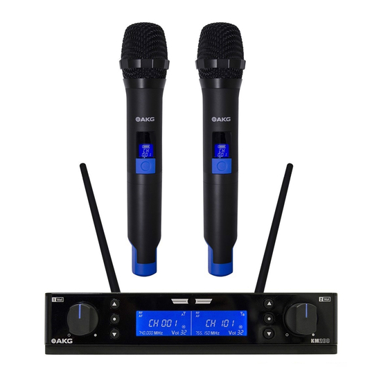
Unpack the system AKG KM200 is consisted by 1 x SR200 wireless receiver and 2 x HT200 handhold wireless transmitters. The system is working on UHF frequency range and provides 200 frequency band option. Within the box, diverse installation accessories were provid- ed, to satisfy the different application. -
Page 7: Product Descriptions
KM200 System Product Descriptions SR200 Wireless Receiver Front Panel 1. Output Gain Control 2. Down NavigationKey 3. Function Key 4. IR Sensor 5. LCD Screen 6. Up Navigation Key 1. Output Gain Control: for output gain adjustment. 4. IR Sensor: for Infrared communication with transceiver. 2. -
Page 8: Sr200 Wireless Receiver Lcd Display
KM200 System SR200 Wireless Receiver LCD Display 1. RF Signal Indicator 2. AF Signal Indicator 7. Key Lock Icon 4. Frequecy Indicator 3. Channel Indicator 5. Output Gain Indicator 6. Mute Icon 1. RF Signal Indicator: show current RF signal status 5. -
Page 9: Ht200 Wireless Transmitter Lcd Display
KM200 System HT200 Wireless Transmitter LCD Display 1. Battery Status Indicator 2. Wireless Channel Status Indicator 1. Battery Status Indicator: indicate the battery status. 2. Wireless Channel Status Indicator: indicate the current using wireless channel. System Operation SR200 Installation 1. Antenna Installation Screw up the 2 antennas on the BNC connectors of the receiver rear panel. -
Page 10: Ht200 Installation
KM200 System 2. Rack Installation AKG has provided the rack installation accessories for KM200, customers are able to combine 2pcs of SR200 with the provided accessories and install them in the rack as below: Front View Angel View HT200 Installation Battery Installation 1. -
Page 11: Setup The System
KM200 System SETUP The System Setup the Working Frequency 1. Setup Manually • Press the “Up/Down Navigation Key” on the SR200 to select the RF channel you would like to use; • Power on the HT200 and aiming the IR sensor on the HT200 to the SR200 IR sensor position; •... - Page 12 KM200 System 3. Lock the Key Panel While the setup process is done, you may lock-up the keys on the SR200 to prevent mistake operation. To lock-up the key panel: • Long press the “Function” key over 3 seconds; • Then the key lock icon will be illuminated on the LCD screen, and now the keys are locked-up.
-
Page 13: Specification
KM200 System Specification HT200 SR200 Carrier frequencies 740-770 MHz 740-770 MHz Switching band width up to 30 MHz 30 MHz Modulation Audio transmission bandwidth 50 - 18,000 Hz 50 - 18,000 Hz Total harmonic distortion at 1 kHz typ. ≤ 0.8% typ. -
Page 14: Channel Number Vs Frequency
KM200 System Channel Number vs Frequency... - Page 15 目录 重要安全信息..........17 概述............18 产品特点............. 19 打开包装............. 19 产品介绍............. 20 SR200无线接收机前面板........20 SR200无线接收机后面板........20 SR200无线接收机LCD屏......... 21 HT200无线发射机..........21 HT200无线发射机LCD屏......... 22 系统操作............. 22 SR200安装指引..........22 HT200安装指引..........23 系统设置............. 24 规格参数............. 26 常见问题............. 26 频道与频率对照表..........27...
- Page 16 符号说明 说明书和设备上都使用了符号,指出可能对用户或他人造成的伤害以及 财产受损的风险,以便您能够安全、正确地使用设备。指示及其含义如 下。请确保在阅读说明书之前正确理解这些符号的警示。 提醒使用者设备内出现的未绝缘危险电压可能使人遭受电击。 电击提示 此为A级产品,在生活环境中,该产品可能会造成无线电干扰。在这种 情况下,可能需要用户对干扰采取切实可行的措施。 警告 表示可能导致操作或设置不成功的内容及一些需要注意的相关信息。 注意 如果您需要丢弃本产品,请勿将其与一般家居废品混放。对于电子产 品的废弃,请遵循当地电子电气设备废弃物指令正确处理、恢复和回 收,将废弃产品统一回收到独立的回收系统。 该产品包装可循环再用。如果您要丢弃该包装,请统一回收到适当的 回收系统。 产品中有毒有害物质或元素的名称及含量: 中国RoHS声明 Mindestgrößen 有毒有害物质或元素 (HAZARDOUS SUBSTANCE) 部件名称 铅 汞 镉 六价格 多溴联苯 多溴二苯醚 (PARTS) (Pb) (Hg) (Cd) (PBB) (PBDE) Mindestgrößen 金属部件 ○ ○ ○ ○...
-
Page 17: 重要安全信息
重要安全信息 阅读本手册。 保留本手册。 留意所有的警告。 安全操作 遵守本手册中的所有操作说明。 不要在近水区域使用本产品。 仅用干布清洁擦拭本产品。 不要阻挡任何通风口,并严格按照制造商提供的操作说明进行安装。 不要靠近任何热源安装,比如散热器、电热器、火炉或者其他产生热 量的设备(包括功放)。 不要破坏具有安全功效的极性插头或者接地式插头。极性插头有两个 插片,一个宽,一个窄。接地式插头有两个插片和一个接地针,其中 宽插片或者接地针是用来保障您的安全的。如果所提供的插头不适合 您的插座,请咨询联系电工更换适合的插座。 10. 保护电源线。避免电源线被踩踏或者被捻搓。特别注意保护在插头、 便捷插座和电源线接出设备处的电源线。 11. 仅使用制造商指定的附件或选件。 12. 仅使用制造商指定的或者随本产品一同出售的载车、支架、三角架、 托架或者工作台。在使用推车运输设备时,特别注意推车及设备,避 免其翻倒造成伤害。 13. 在有雷电时或者长时间不使用本设备时,请拔掉插头。 14. 所有维修服务必须由有资格的维修人员提供。当设备受到任何形式的 损坏时,比如电源线或者插头被损坏,液体或者异物掉入设备,遭受 雨淋或受潮,不能正常工作,以及被摔碰等情况,都需要维修。 15. 警告:为了减小起火或者电击的风险,不要让设备遭受雨淋或者受 潮。 16. 不要将设备放置在容易遭受滴漏或者喷洒的地方。例如,不要将装有 液体的物品,比如花瓶等放到设备上。 为了避免电击,请不要拆卸设备。设备内部无用户可以自行维护的部件。 请向有资格的服务人员咨询。 电击提示 要完全断开此设备与交流电主线的连接,请把电源线插头从交流电插座中 拔出。需要连接电源时,可再次将电源线插头插入交流电插座。... - Page 18 KM200无线麦克风系统 概述 AKG KM200是专门针对KTV房间应用而设计的无线麦克风,其工作在UHF 超高频段,采用了AKG经典的无线发射和接收线路设计,确保传输更稳 定,音质更完美。KM200提供200个可选频道,可满足KTV 娱乐场所内多 套同时使用无干扰。拥有领先的自动扫频技术,一键即可搜索环境中干 净的频点。先进的红外对频技术,使设置更轻松,快速,简单。 • 本产品通过电源线的接地导线接地,为避免电击,必须将接地导 线与大地相连,在对本产品的输入端或输出端进行连接之前,请 务必将本产品正确接地。 警告 • 为避免数据遗失和失误及系统故障和损坏,请勿擅自更改连接线 路,使用任何系统组件对其进行操控,或在进行软件更新时断开 系统电源。 • 为避免对系统组件造成任何损坏,请勿在系统通电状态下,铺 设、连接或断开任何线缆。在对系统连线前,请务必确保已断开 系统的电源连接。 • 此设备的接线工作必须由专业人员或经过培训的人员进行操作。...
-
Page 19: 产品特点
• UHF频段,避免干扰,传输更稳定 • 提供200个可选频道,满足多套系统同时使用 • 采用先进的自动扫频技术 • 红外对频技术,实现快速对频 • 防碰撞保护功能 • 手持发射机发射功率两档可调,满足不同应用需求 • 接收机面板锁键功能,避免使用误操作 打开包装 AKG KM200 由一台SR200无线接收机和两只HT200手持无线麦克风组成。系统工作在UHF频率范围,提供 200个可选通道。KM200包装内提供了丰富的安装支架,用户可以根据需要选择使用,两台SR200无线接 收机可以组合安装在标准机柜上。 • SR200 x 1 • 音频线 x 1 接收机 连接SR200接收 机至功放 • 电源适配器 x 1 • HT200 x 2 发射机... -
Page 20: 产品介绍
KM200系统 产品介绍 SR200无线接收机前面板 1.输出增益控制旋钮 2.向下导航键 3.功能键 4.红外线通讯头 5. LCD屏 6.向上导航键 1. 输出增益控制旋钮:用于输出增益调节 4. 红外线通讯头:与发射机红外线口对接通讯 2. 向下导航键:用于选择导航菜单 5. LCD屏:显示目前状态信息 3. 功能键:确认选择 6. 向上导航键:用于选择导航菜单 SR200无线接收机后面板 7.接收灵敏度调节钮1 8.接收灵敏度调节钮2 1.电源开关 2.电源接口 3.天线 4.平衡输出口2 5.非平衡输出口 6.平衡输出口1 1. 电源开关:接收机电源开关 5. 非平衡输出口:混合信号输出 2. 电源接口:外接电源适配器 6. 平衡输出口1:第一通道XLR平衡信号输出 3. 天线:UHF波段天线 7. -
Page 21: Sr200无线接收机Lcd屏
KM200系统 SR200无线接收机LCD屏 7.锁键图标 1.射频信号强度显示 2.音频信号强度显示 4.频率显示 3.频道显示 5.输出信号增益值 6.静音图标 1. 射频信号强度显示:显示目前射频信号强度 5. 输出信号增益值:目前输出信号增益 2. 音频信号强度显示:显示目前音频信号强度 6. 静音图标:表示系统处于静音状态 3. 频道显示:显示目前所占用频道 7. 锁键图标:表示系统除音量旋钮可调以外, 其余按键处于锁定状态 4. 频率显示:目前频道所使用频率 HT200无线发射机 2.上管体 3.显示屏 5.下管体 6.天线 1.网罩 4.电源开关 1. 网罩:保护里面的拾音头 4. 电源开关:开启与关闭发射机 2. 上管体:与下管体一同进行电池仓与手持杆 5. 下管体:与上管体一同进行电池仓与手持杆 3. LCD屏:显示电池与频道信息 6. -
Page 22: Ht200无线发射机Lcd屏
KM200系统 HT200无线发射机LCD屏 1. 电池状态显示 2. 无线频道显示 1. 电池状态显示:显示电池电量 2. 无线频道显示:显示目前使用频道 系统操作 SR200安装指引 1. 天线的安装 将两根可拆卸天线安装于接收机背板的BNC接头之上,旋紧卡住。调整两根天线的角度,以呈“V”字 型。如下图: BNC接口 V字型... -
Page 23: Ht200安装指引
KM200系统 2. 机柜安装 AKG KM200提供了可供机柜安装的配件,用户可根据需要将两台KM200接收机组合安装于机柜之中。如 下图所示: 正面安装图 斜视图 HT200安装指引 电池安装 1. 旋开发射机下管体,即可看见电池仓; 2. 按标示装入两节5号AA电池,并确认电池正负极安装正确; 3. 选择合适的发射功率。通过位于电池仓旁边的开关,选择发射器的的发射功率,共有高低两档可 选。 选择开关: H - 高功率 L - 低功率 发射功率档位开关 发射功率档位开关... -
Page 24: 系统设置
KM200系统 系统设置 设置工作频道 1. 手动设置 • 在SR200前面板上按“上/下”导航键选择需要的RF频道; • 打开HT200并将显示屏位置对准SR200红外线通讯头位置; • 长按SR200的向上导航键3秒钟,此时LCD显示屏会显示“ “ 字样并闪烁,表示系统正在 进行红外线对频; • 红外线对屏成功后,HT200上的频道将会自动调到与SR200一致,RF信号条点亮。 红外线通讯对接 2. 自动设置 • 按下SR200前面板上的功能键,LCD屏会显示“CH SCA“ 字样; • 按上/下导航键开启自动扫频程序,SR200会自动在50个信道里搜索干净信道。如果找到干净信 道,则SR200会停止扫描并显示此干净信道;如果找不到干净信道,SR200会回到扫描状态,等待 用户按“向上键”或“向下键”继续扫描(即每扫50个信道后,如果没有找到干净信道,SR200 会暂停,需用户手动启用扫描功能继续扫描); • 打开HT200并将显示屏位置对准SR200红外线通讯头位置; • 长按SR200的向上导航键3秒钟,此时LCD显示屏会显示“ “ 字样并闪烁,表示系统正在进 行红外线对频; • 红外线对屏成功后,HT200上的频道将会自动调到与SR200一致,RF信号条点亮。... - Page 25 KM200系统 3. 面板按键上锁 当频率设置完成后,您可以锁上SR200前面板的按键功能,以防止误操作 按键上锁: • 长按“功能”键3秒钟; • 此时LCD屏幕上方的锁键图标会点亮并闪烁,这时前面板上的按键已经上锁 按键解锁: • 长按“功能”键3秒钟; • 此时LCD屏幕上方的锁键图标会消失,这时前面板上的按键已经解锁 锁键图标 锁键图标 4. 通道静音 你还可以在SR200前面板上设置通道静音 设置静音: • 长按“向下导航键”键3秒钟; • 此时LCD屏幕上方的静音图标会点亮并闪烁,此时该通道已静音; 取消静音: • 长按“向下导航键”键3秒钟; • 此时LCD屏幕上方的静音图标会消失,此时该通道已恢复音量; 静音图标 静音图标...
-
Page 26: 规格参数
KM200系统 规格参数 HT200 SR200 740-770 MHz 740-770 MHz 载波频率 30 MHz 30 MHz 载波带宽 调制 50 - 18,000 Hz 50 - 18,000 Hz 音频频响范围 THD @ 1 kHz typ. ≤ 0.8% typ. ≤ 0.8% typ. 105 dB(A) typ. 105 dB(A) 信噪比... -
Page 27: 频道与频率对照表
KM200系统 频道与频率对照表... - Page 28 Microphones • Headphones • Wireless Microphones • Wireless Headphones • Headsets • Elec- troacoustical Components 话筒 • 耳机 • 无线话筒 • 无线耳机 • 耳麦 • 电声组件 AKG Acoustics GmbH Lemböckgasse 21ö25, A-1230 Vienna/AUSTRIA, phone: +43 1 86654 0 e-mail: sales@akg.com For other products and distributors worldwide visit www.akg.com 有关其他产品和全球经销商的信息,请访问...
Need help?
Do you have a question about the AKG KM200 and is the answer not in the manual?
Questions and answers