Table of Contents
Advertisement
Quick Links
Advertisement
Table of Contents

Related Manuals for Harman AKG DMS800


Summary of Contents for Harman AKG DMS800
- Page 1 DMS800 Manual DIGITAL WIRELESS MICROPHONE SYSTEM...
-
Page 2: Table Of Contents
Contents Contents General ..........5 Commissioning ......19 1.1 Purpose of the manual ......5 6.1 Insert batteries into the transmitter..19 1.2 Retention of the manual ......5 6.2 Connecting the antennae ..... 19 1.3 Liability ........... 5 6.3 Position the receiver ......20 1.4 Warranty .......... - Page 3 Contents 12.3 AUDIO menu ........39 9.1.2 Functions in SETUP mode ..........12.4 ENVIR. menu SCAN ......40 9.1.3 Possible functions in the main window .... 9.2 Functions of the CH1, CH2 (10, 12) 12.5 REHEARSAL menu ......40 buttons ..........30 12.6 UTILITY menu ........
- Page 4 Publishing information Publisher AKG Acoustics GmbH Laxenburger Straße 254 1230 Wien Austria Tel: +43 (0)1 86654-0 Fax: +43 (0)1 86654-8800 sales@akg.com Copyright © 2015 AKG Acoustics GmbH. All rights reserved. The information contained in this manual, including any drawings and photos provided, are the intellectual property of AKG Acoustics GmbH.
-
Page 5: General
General General Purpose of the manual This manual is intended to enable you to: • operate the equipment safely • use the equipment correctly. Retention of the manual Keep this manual carefully and in an easily accessible location. Pass this manual on to subsequent owners. This manual is an important part of the equipment. -
Page 6: Package Content
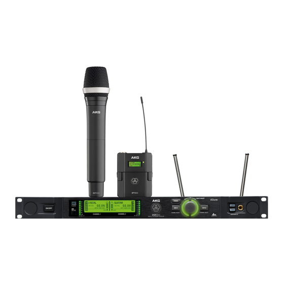
Package content Package content Check that the package contains all the parts given below. If anything is miss- ing, please contact your AKG dealer. DSR800 • 1 x DSR800 receiver DSR800 • 2 x BNC UHF antennae • 2 x antenna cables for front mounting 0110E01890 •... - Page 7 Package content Other options and antenna accessories are available in the current AKG cata- logue as a download from www.akg.com. Your dealer will be happy to advise.
-
Page 8: Safety And Environment
Safety and environment Safety and environment Safety • Protect the equipment against - direct sunlight - the impact of significant dust and humidity - rain - vibrations or knocks. Safety • Do not spill any liquids on the equipment and do not allow any other ob- jects to drop through the ventilation slits into the equipment. -
Page 9: Explanation Of The Symbols Used
Safety and environment • To avoid hum or interference, route all audio lines, particularly those con- nected to the microphone inputs, away from power lines of any type. If you use cable ducts, be sure to use separate ducts for the audio lines. •... -
Page 10: Environment
Declaration of Conformity Environment Disposal • Always dispose of empty batteries in accordance with the relevant dispos- al regulations. Never throw batteries into naked flame (risk of explosion) or into the household waste under any circumstances. • The packaging is recyclable. Dispose of the packaging in an appropriate recycling collection system. •... -
Page 11: Equipment Description
Equipment description Equipment description General description The DMS800 consists of the following parts: Description • DSR800 digital stationary true diversity transmitter • DHT800 handheld transmitter and/or DPT800 bodypack transmitter There is the choice of AKG microphone heads with the handheld transmitter: •... - Page 12 Equipment description System data ≤ 0.02 % Signal-to-noise ratio analogue: XLR symmetrical, typ. 115 dB(A) (A-evaluated) digital: AES-EBU, typ. 120 dB(A) digital: DANTE Net. Interface, typ. 120 dB (A) Audio sampling rate 24 Bit / 44.1 kHz Modulation digital Bit rate < 200 kbps Compressor AKG Premium Audio Compressor/dbx®...
- Page 13 Equipment description Digital True Diversity receiver DSR800 Bass roll off 10 – 300 Hz Equalizer 3-Band (parameters: low, mid and high enhance- ment Compressor dbx® (parameters: amplification, response threshold, ratio, attack, release) Limiter dbx® (parameter: usage threshold) Transmitter battery 7-part indicator PC interface Ethernet via HUB 4000 Q Ethernet via DANTE (100 Mbit/s) Software HiQnet Audio Architect Power supply...
-
Page 14: Dsr800: Description Of The Controls
Equipment description Digital handheld transmitter DHT800 Carrier frequency Band 1: 548.1 - 697.9 MHz (country-dependent) range Band 2: 710.1 – 831.9 MHz (country-dependent) Switching bandwidth ≤ 150 MHz (country-dependent) Transmission power 10, 20, 30, 50 mW (ERP max.), can be set via menu (country-dependent) Scatter ≤ -70 dBc Antenna... - Page 15 Equipment description No. Description Headphone buttons (CH1, CH2) Headphone output: 6.3 mm jack socket Infrared receiver window for data synchronisation HF level indicator Channel selector button for channel CH1 Light ring for status display for channel CH1 and CH2 (red = warning, green = OK) Channel selector button for channel CH2 Opening for antenna front mounting Antenna input A: BNC socket...
-
Page 16: Dsr800: Description Of The Display Elements
Equipment description DSR800: Description of the display elements The following table describes the display elements of the DSR800 (figure on DSR800 display page 53): Letter Description Alphanumeric name display Current group and channel number 7-part status display of the transmitter battery Symbol for LOCK mode (button lock) Audio level indicator MUTE symbol Current frequency... -
Page 17: Dpt800: Description Of The Display Elements
Equipment description No. Description Battery compartment for 2 LR6 (AA) 1.5 V batteries or 1.2 V NiMH rechargeable batteries, size AA (>2100 mAh) 2.5 mm jack socket for external MUTE switch Charging contacts Locking button for battery compartment cover DPT800: Description of the display elements The following table describes the display elements of the DPT800 (figure DPT800 display on page 54):... -
Page 18: Dht800: Description Of The Display Elements
Equipment description No. Description On/off switch Battery compartment cover Microphone heads D5 WL1, D7 WL1 or C5 WL1 Battery compartment for 2 LR6 (AA) 1.5 V batteries or 1.2 V NiMH rechargeable batteries, size AA (>2100 mAh) DHT800: Description of the display elements The following table describes the display elements of the DHT800 (figure DHT800 display on page 54):... -
Page 19: Commissioning
Commissioning Commissioning Before commissioning your DMS800, check that the transmitter and receiver are set to the same frequency. To commission the DMS800, proceed as follows: 1. Insert batteries into the transmitter 2. Connect the antenna 3. Position the receiver 4. Connect the receiver to the mixing console/amplifier 5. -
Page 20: Position The Receiver
Commissioning To mount the λ/4 antennae , proceed as follows: Step Description 1 Mount λ/4 antennae onto the front panel (13); use BNC front mounting cable (AKG part no. 0110E01890) to do this. To mount the remote antennae, proceed as follows: Step Description 1 Connect remote antennae with BNC sockets (14) and (15) to the rear of the receiver;... -
Page 21: Connecting The Receiver To The Mixing Console/Amplifier
Commissioning Connecting the receiver to the mixing console/ amplifier The DSR800 receiver has the following outputs • Analogue outputs • Digital outputs 6.4.1 Analogue outputs Both analogue XLR outputs (17, 20) and both analogue 6.3 mm jack outputs can be connected at any time. The output level can be set accordingly in the AUDIO menu. -
Page 22: Digital Output: Aes-Ebu
Commissioning CAUTION: If you set the IP address of the DANTE™ network manually via the software, it is essential that you note down the IP address set. Alternatively, before removing the device from the network, set the IP address to "Automatic" using the software so that the device is detected in a new net- work by the DANTE™... - Page 23 Commissioning To connect the receiver to the power network, proceed as follows: Step Description 1 Connect the mains cable to the AC IN socket (26) on the rear of the receiver and plug into a suitable mains socket...
-
Page 24: Quick Setup
QUICK SETUP QUICK SETUP The QUICK SETUP function allows intermodulation and interference-free carrier frequencies to be found for all channels quickly and easily. To carry out a QUICK SETUP, proceed as follows: Step Description 1 Switch on the receiver by pressing the ON/OFF switch 2 Select the START SETUP menu by pressing the SELECT wheel three times 3 Confirm the number of channels by pressing the SELECT wheel... -
Page 25: Operating Instructions
Operating instructions Operating instructions Setting the carrier frequency The following steps are required to set the carrier frequency: Carrier frequency 7. Set the transmitter to SILENT mode (recommendation) 8. Unlock the receiver 8.1.1 Setting the transmitter to SILENT mode We recommend setting the carrier frequency in SILENT mode (no HF radia- tion). -
Page 26: Switch On Mute Lock
Operating instructions Switch on MUTE LOCK To avoid the MUTE switch on the transmitter being switched on accidentally, it can be locked via the receiver. To lock the MUTE switch, proceed as follows: Step Description Switch on the receiver Select the CHANNEL menu; to do this, turn the SELECT wheel to the right Press SELECT MUTE LOCK... -
Page 27: Carrying Out A Sound Check
Operating instructions Carrying out a sound check To carry out a sound check, proceed as follows: Step Description Switch on the receiver Select the REHEARSAL menu; to do this, turn the SELECT wheel to the right Switch on synchronised transmitter Sound check Start REHEARSAL;... -
Page 28: Selecting The Country
Operating instructions Selecting the country Use the frequencies of the sets preprogrammed for your country. However, ensure that you have the licence for the transmission frequencies of the country, if required. To select the country, proceed as follows: Step Description Switch on the receiver Selecting the country... -
Page 29: Controls On The Dsr800 Receiver
Controls on the DSR800 receiver Controls on the DSR800 receiver The functions of the individual controls on the receiver vary depending on the receiver mode. The following modes are possible: • LOCK mode: Receiver is locked, no setting options • SETUP mode: Receiver is unlocked, setting options available Functions of the SELECT wheel (5) 9.1.1 Functions in LOCK mode Long press... -
Page 30: Functions Of The Ch1, Ch2 (10, 12) Buttons
Controls on the DSR800 receiver Functions of the CH1, CH2 (10, 12) buttons 9.2.1 Functions in LOCK mode In the main window Channel window for parameter overview, no chang- es possible 9.2.2 Functions in SETUP mode In the main window Channel window for parameter setting, no changes possible Functions of the BACK button (4) -
Page 31: Display Of The Dsr800 Receiver
Display of the DSR800 receiver 10 Display of the DSR800 receiver 10.1 Main window Main window After the DSR800 receiver is switched on, the main window is displayed. The main window displays all parameters required for operation: • Name • Current frequency •... -
Page 32: Mute Indicator
Display of the DSR800 receiver 10.2.2 MUTE indicator The audio output is muted. The light MUTE indicator ring (11) lights up red. As the power supply and the HF sec- tion remain switched on, no interfer- ence is audible. 10.2.3 Antenna indicator The DSR800 receiver is a specially developed, digital True Diversity receiver Antenna with integrated antenna splitter. The antenna field (H) displays the antenna... -
Page 33: Status And Warning Displays By Urgency
Display of the DSR800 receiver 10.3.1 Status and warning displays by urgency Display Symbol Meaning LOW BATT The capacity of the transmitter battery Warning will soon be depleted. The light ring displays changes to red and the display shows a large warning continuously. AF CLIP The audio signal overrides the A/D converter of the transmitter. -
Page 34: Channel Window
Display of the DSR800 receiver Display Symbol Meaning ENCRYPTION The encryption is not set correctly. 10.4 Channel window The channel window offers a rapid overview of the following tuning parame- Channel ters: window • Group/channel • Frequency • Name • Country • Audio input level of the handheld or bodypack transmitter •... -
Page 35: Display Of The Dht800/Dpt800 Transmitter
Display of the DHT800/DPT800 transmitter 11 Display of the DHT800/DPT800 transmitter 11.1 Battery indicator The battery indicator on transmitter (C) and receiver (C) allow the remaining Transmitter capacity of the transmitter battery to be checked at a glance. display Each segment corresponds to approx. 1 hour remaining playback time. If no battery voltage is measured or the information is invalid, there is no indicator on the display. -
Page 36: Menu Structure Of The Dsr800 Receiver
Menu structure of the DSR800 receiver 12 Menu structure of the DSR800 receiver MAIN WINDOW CHANNEL WINDOW BACK < > < > < > < > < > QUICK SETUP CHANNEL AUDIO ENVIR. SCAN REHEARSAL UTILITY Search for and Set parameters Set audio editing: Search frequency Check HF reception... -
Page 37: Quick Setup Menu
Menu structure of the DSR800 receiver 12.1 QUICK SETUP menu QUICK SETUP Search for and set free carrier frequencies START SETUP NO. CHANNELS LIMIT FREQ. RANGE START SCAN Search channel Number of required Limit frequency Start new search groups to find, set range search SELECT: start channels <... -
Page 38: Channel Menu
Menu structure of the DSR800 receiver 12.2 CHANNEL menu CHANNEL Set parameters manually Synchronise channel < > < > < > GROUP/CHANNEL CH1/CH2 GROUP CHANNEL SYNC Set group and Select receiver part Select group Select channel Synchronise channel manually SELECT: Select/save SELECT: select SELECT: select/save transmitter SELECT:... -
Page 39: Audio Menu
Menu structure of the DSR800 receiver 12.3 AUDIO menu AUDIO Set audio editing: Gain, bass roll off, EQ, compressor, limiter SELECT < > CH1,CH2 GAIN CH1/CH2 GAIN Select receiver part Set input level for DSP Set input level for DSP chain SELECT: Select/save (audio) chain SELECT: BACK setting... -
Page 40: Envir. Menu Scan
Menu structure of the DSR800 receiver 12.4 ENVIR. menu SCAN ENVIR. SCAN Search frequency band for active radio frequencies SELECT CH1,CH2 UNLIMITED SCAN GRAPH Search entire Interference frequencies are searched frequency band BACK SELECT: Enlarge display < >: move to the left or right <... -
Page 41: Utility Menu
Menu structure of the DSR800 receiver 12.6 UTILITY menu UTILITY General settings SELECT < > < > < > STATUS RF LOW LOW BATT AUDIO CLIP ANT ERR Program optical Warning: no transmitter Warning: Transmitter Warning: Audio signal Warning: Error on antenna warnings for critical signal received battery will soon be empty... -
Page 42: Menu Structure Of The Transmitter
Menu structure of the transmitter 13 Menu structure of the transmitter To switch on the transmitter, proceed as follows: Step Description 1 Press the ON/OFF button for 2 seconds 13.1 Preset mode After synchronisation of a group and a channel, the group (GR), channel (CH) and country appear on the display. -
Page 43: Silent Mode
Menu structure of the transmitter 13.3 Silent mode To switch on the transmitter in silent mode, pro- ceed as follows: Step Description GROUP/CHANNEL 1 When switching on the ON/OFF Display shows the group, channel and frequency (no HF signal) switch (6), press with the MUTE switch (2) held down at the same time The entry RF-OFF is shown on the... -
Page 44: Functional Description
Functional description 14 Functional description The DSR800 has been developed for operation in large multi-channel sys- tems. 14.1 CHANNEL menu This menu can be used to manually set all parameters relevant for a channel such as group/channel, frequency, name, input level of the bodypack trans- mitter, encryption and MUTE LOCK. - Page 45 Functional description Submenu Function ENCRYPTION Activate the encryption function When the encryption function is activated, the receiver calculates a one-off key every time a transmitter is synchronised. This key is sent to the transmitter during the synchronisation pro- cess. The key is not displayed and it is not possi- ble to send the same key to two transmitters.
- Page 46 Functional description Submenu Function Edit audio signal directly on the receiver Settings can be stored in one of the nine DPS profiles in a freely selectable name. The digital signal processor offers the following dynamic editing functions: • Low Cut (frequency: 10 - 300 Hz) • 3-band equalizer (low: ±20 dB, 80 Hz shelv- ing;...
- Page 47 Functional description Submenu Function REHEARSAL Sound check Check HF level of the transmitter in the action area The maximum recording time is four minutes UTILITY STATUS Activate optical warning function for specific critical operating conditions If one of these operating conditions occurs, the light ring around the SELECT wheel on the receiver changes from green to red and a corre- sponding status display is shown on the display.
- Page 48 Functional description Submenu Function INFO Call up information on the receiver software and the transmitters synchronised with it WARNING LIST Calling up warning messages This function saves the last 25 warning messag-...
-
Page 49: Maintenance And Cleaning
Maintenance and cleaning 15 Maintenance and cleaning 15.1 Maintenance The equipment must only be opened, serviced and repaired by authorised personnel. The equipment contains no user-serviceable parts. 15.2 Cleaning Caution: Unplug the DSR800 receiver mains cable from the socket! Clean the surface of the equipment with a soft cloth moistened with water. Never use caustic or scouring cleaners or cleaning products containing alco- hol or solvents since these may damage the enamel and plastic parts. -
Page 50: Troubleshooting
Troubleshooting 16 Troubleshooting Error Possible cause Correction No sound Errors due to other wireless systems, Switch off other wireless systems TV, radio, wireless devices or harmful electrical equipment or installations. Transmitter set to a frequency different Set transmitter to the frequency from the receiver. Transmitter switch or MUTE switch on Switch on transmitter or press the "MUTE". - Page 51 Troubleshooting Error Possible cause Correction RF LOW The field strength of the reception signal Reposition receiver or use remote is so low that the receiver is automati- antennae. cally muted to avoid interference noise. AF CLIP The audio signal overrides the A/D con- Reduce audio input level. verter of the transmitter.
-
Page 52: Dsp Profiles: Factory Settings
Troubleshooting 16.1 DSP profiles: Factory settings LOW CUT COMPRESSOR LIMITER Profile Name Application Freq. [Hz] High Threshold Ratio Gain Attack Release Threshold [dB] [dB] Freq [dB] [dB] [dB] [ms] [ms] [dB] [kHz] Beginners, Handheld Present HT 2.1:1 transmitter MS Powerpoint, churches, pre- Headset Present PT... -
Page 53: Dms800: Controls
DMS800: Controls 17 DMS800: Controls 17.1 DSR800 100-240V~ 0,35-0,2A 50/60Hz 15 16 17 18 19 20 21 22 23 24... -
Page 54: Dpt800
DMS800: Controls 17.2 DPT800 17.3 DHT800...
Need help?
Do you have a question about the AKG DMS800 and is the answer not in the manual?
Questions and answers