
Related Manuals for Q CELLS SL Series


Summary of Contents for Q CELLS SL Series
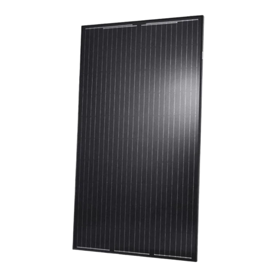
- Page 1 CIGS SOLAR MODULES Q.SMART & SL SERIES Installation and operation manual for Q.SMART, Q.SMART UF, Q.SMART UF L, SL1, SL1-F, SL2...
-
Page 2: Table Of Contents
INTRODUCTION PAGE 3 PRODUCT DESCRIPTION PAGE 4 SAFETY INSTRUCTIONS PAGE 5 TRANSPORT AND STORAGE PAGE 5 AREA OF USAGE AND INSTALLATION LOCATION PAGE 6 LAYOUT, MOUNTING AND INSTALLATION PAGE 7 MOUNTING LAYOUTS PAGE 8 MECHANICAL MOUNTING - UNFRAMED MODULES PAGE 10 MECHANICAL MOUNTING - FRAMED MODULES PAGE 11 ELECTRICAL LAYOUT... -
Page 3: Introduction
1 INTRODUCTION Q-Cells CIGS solar modules allow you to directly transform Information for operators the unlimited energy provided by the sun into environmentally Keep these instructions safe for the entire life of the mod- friendly electrical energy. ule. Particularly observe chapters 6 (troubleshooting) and 7 In order to be able to completely exploit the full performance (cleaning and maintenance). -
Page 4: Product Description
2 PRODUCT DESCRIPTION Q.SMART TECHNICAL DATA (you can find additional data in the respectively valid data sheets at www.q-cells.com) PRODUCT LINE Q.SMART UF (SL1) Q.SMART UF L (SL2) Q.SMART (SL1-F) Type unframed unframed framed Area [m²] 0,75 0,94 0,76 Weight [kg] 13,2 16,5 14,5... -
Page 5: Safety Instructions
3 SAFETY INSTRUCTIONS SAFETY INSTRUCTIONS DANGER! Danger due to electric shock! A solar module generates electricity and voltage even at a low intensity of illumination. Arc- ing can occur when contacts in a live electrical circuit are physically disconnected. This can result in grave or mortal injury. -
Page 6: Area Of Usage And Installation Location
4 AREA OF USAGE AND INSTALLATION LOCATION INSTALLATION • The modules are certified according to the norm IEC 61646 for safe operation in moderate LOCATION climates. • The permitted module temperatures lie between -40 °C and +85 °C. Please ensure that adequate ventilation exists below the module so that elevated module temperatures can be avoided. -
Page 7: Layout, Mounting And Installation
5 LAYOUT, ASSEMBLY AND INSTALLATION SAFETY INSTRUCTIONS WARNING! Damaged module components may cause risk of fire hazard! • Only install undamaged solar modules. • Ensure that the junction box, cable and connectors are undamaged prior to installation. • Do not open the junction box under any circumstances. •... -
Page 8: Mounting Layouts
5.1 MOUNTING VARIANTS POINT SUPPORT THE FOLLOWING MOUNTING VARIANTS ARE POSSIBLE: Substructure lateral beneath the module with 2 (A ) or 3 (A ) clamps per module side Substructure under the long sides with 2 (B ) or 3 (B ) clamps per module side LINEAR SUPPORT FOR With linear support, the modules lie along the lateral sides on the substructure. - Page 9 MODULE ORIENTATION CAUTION! Incorrect orientation of the module may cause risk of fire hazard! • The modules may be installed in landscape or portrait format. • Framed modules must be installed with a minimum inclination angle according to chapter 4. • Unframed modules can be installed roof-parallel with a minimum inclination angle of 3°. •...
-
Page 10: Mechanical Mounting - Unframed Modules
5.2 MECHANICAL ASSEMBLY - UNFRAMED MODULES CLAMP SYSTEMS Only install clamp systems approved by Q-Cells. Failure to do so will void the warranty. A list of released clamp systems can be furnished upon request to Q-Cells. Upon request, Q-Cells can test clamp systems and release them for use upon successful test- ing. -
Page 11: Mechanical Mounting - Framed Modules
5.3 MECHANICAL MOUNTING - FRAMED MODULES CLAMP SYSTEMS Fasten the module with 4 clamps each and a recommended torque of 18 Nm to the rails. If the information of the clamp manufacturer differs from this recommendation, the values of the clamp manufacturer are to be used. -
Page 12: Electrical Layout
5.4 ELECTRICAL LAYOUT YOU CAN FIND THE DETAILED ELECTRICAL PARAMETERS IN THE PRODUCT DATA SHEET. MODULE SELECTION Only connect modules of the same type and the same power class. This is the only way to achieve optimal yields. SAFETY FACTOR It may occur during normal operation that the module provides a greater current and / or a higher voltage than that determined under standardized test conditions. - Page 13 INVERTER The choice of inverter depends on the country of the installation (see table 1): • in countries where functional grounding is required: inverter with galvanically isolated transformers must be used • in countries where functional is not required: inverters with our without transformers can be used.
-
Page 14: Electrical Installation
5.5 ELECTRICAL INSTALLATION SAFETY INSTRUCTIONS DANGER! Life danger due to electric shock! When disconnecting a DC circuit, electric arcs can occur that can result in dangerous injuries. • Carry out work on the inverter and the electrical cables with extreme caution. •... -
Page 15: Cleaning And Maintenance
7 CLEANING AND MAINTENANCE Q-Cells CIGS modules are built to last and require minimal maintenance. Light dirt is typically washed away by rain. However, precipitation may not adequately clear more stubborn grime (i.e. pollen, vegetation, bird droppings, etc.). Such contamination which shades the active area of the module can lead to a reduction in its performance. -
Page 16: Contact
CONTACT Q-CELLS SE +49 (0)3494 66 99 - 0 OT Thalheim +49 (0)3494 66 99 - 199 Sonnenallee 17–21 EMAIL service@q-cells.com 06766 Bitterfeld-Wolfen WEB www.q-cells.com Germany...
Need help?
Do you have a question about the SL Series and is the answer not in the manual?
Questions and answers