Table of Contents
Advertisement
Advertisement
Table of Contents

Subscribe to Our Youtube Channel
Related Manuals for Aimco Auditor AUET/MTM


Summary of Contents for Aimco Auditor AUET/MTM
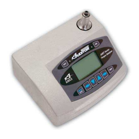
- Page 1 AUET & AUET/MTM Desktop Torque Testers User Guide...
-
Page 2: Table Of Contents
CONTENTS Safety Requirements ..............................Descriptions and Specifications Screen and button Diagram ............................... 4 Side Panel Diagram ................................5 Back Panel Diagram ................................. 5 Unit Specifications ................................5 Operating Instructions Charging the AUET ................................6 Basic Navigation ................................6 Turning On / Off ................................6 Preparing the AUET for Use ............................. -
Page 3: Safety Requirements
SAFETY REQUIREMENTS SAVE THESE INSTRUCTIONS WORK AREA Keep work area clean and well lit. Cluttered and dark areas invite accidents. Do not operate power tools in explosive atmospheres, such as the presence of flammable liquids, gases or dust. Power tools create sparks which may ignite the dust or fumes. Keep children and bystanders away while operating a power tool. -
Page 4: Screen And Button Diagram
SCREEN AND BUTTON DIAGRAM Figure 1 Data Display OK Rundown / Charging Mode Indicator LED (GREEN) Operating Mode Right Selection Button Menu Mode Status Data Storage Mode Selection Arrow – Down Increase Parameter Value Change Operating Mode Select Parameter Scroll Down through Menu screens Selection Arrow - Up Left Selection Button Change Engineering Units... -
Page 5: Side Panel Diagram
Figure 2 AUET/MTM Models Only Transducer Transducer Selection Input Figure 3 DC Power RS232 Serial Input Output UNIT SPECIFICATIONS Dimensions Width: 8.250”, Height: 3.50” (w/o Joint Simulator), Depth: 6.250” Weight Power Requirements Main power 100-240VAC, 60hz from supplied charger, or internal NiMH battery pack Operating Temperature Range to 50 Data Communication... -
Page 6: Charging The Auet
Turning On / Off To turn the AUET on, press the “ON” button (Figure 1) The AIMCO logo will be displayed for approximately 4 seconds followed by the following display: To turn the AUET off, simply press the “OFF” button. -
Page 7: Preparing The Auet For Use
the concave curves in the same direction a simulated hard joint is achieved (Fig. B). Alignment of the concave shapes in an opposing manner a simulated soft joint is achieved (Fig. C). Differing combinations allow for simulated medium joints to be achieved (Fig. D). Fig. -
Page 8: Selecting The Proper Data Mode
complete. Data will be displayed on the screen until manually cleared or until preset Auto Clear time has elapsed. No values are stored while in RUN mode. MEMORY mode displays the Torque data from the run and stores it sequentially in the internal memory of the tester. The memory location is displayed in the upper left corner of the tester screen. -
Page 9: Storing Rundown Torque Values
associated statistical information. With the AUET turned ON, observe the Data Storage Mode Status field (Figure 1). If MEM is displayed, the AUET is in MEMORY MODE and can then be configured accordingly. If the status reads RUN, then the AUET is in RUN MODE and will not store any of the following rundown values. -
Page 10: Reviewing Rundown Torque Values
values above 10 will display as zero values. Reviewing Statistical Information Once rundown torque values have been stored to memory, it is possible to view statistical values based on those rundowns. To view statistical information: From either MEMORY MODE or RUN MODE press the MENU button. Press the UP menu scroll button until the Data Menu (3 of 3) item is displayed Press SEL to enter into the Data Menu area Press the UP menu scroll button until Display SPC Info 3 of 5) item is shown... -
Page 11: Peak Options Menu
Peak Options Menu (1) Accessing the PEAK OPTIONS menu To access the PEAK OPTIONS menu: From the Main Display screen, press MENU PEAK OPTIONS MENU should be displayed. If it is not, use the SELECTION ARROW buttons to display. Press the Right Selection button for SELECT (SEL) The user can then use the SELECTION ARROW buttons to scroll through the following options in the order shown: Auto Clear... -
Page 12: Peak Blanking
Peak Blanking (1-3) PEAK BLANKING determines the minimum threshold at which a torque peak is captured. It is entered as a percentage of the full scale value of the transducer contained in the AUET and can be displayed in values from 2 – 50% of transducer full scale. -
Page 13: Edit Limits
Edit Limits (1-6) By using the EDIT LIMITS feature to set high and low limits for torque readings, the user can receive visual feedback regarding the rundown results. Setting the HIGH and LOW limits appropriately will result in the following display signals: Reading outside of set limits: A RED LED being lit on the AUET (Next to OFF button) symbol for LOW readings and a... -
Page 14: System Menu
System Menu (2) Accessing the System Menu To access the SYSTEM menu: From the Main Display screen, press MENU Use the Selection Arrow buttons to scroll to System Menu Press the Right Selection button for SELECT (SEL) The user can then use the SELECTION ARROW buttons to scroll through the following options in the order shown: Sleep (2-1) To conserve battery life, the AUET is equipped with a SLEEP mode. -
Page 15: Contrast
Print Data Requirements Data can be transmitted by cable through the built in Serial port using AIMCO’s Part # RS232C. The data can be transmitted to a serial printer or to a terminal emulation program on the user’s computer PC such as Hyper... -
Page 16: Rs232 Transfer Protocol
Unused Ground Print Memory (3-1) Connect the AUET to a serial printer or computer using the appropriate cable (AIMCO part # RS232C) From the Main Display screen, press MENU Use the Selection Arrow buttons to scroll to Data Menu Press the Right Selection button for SELECT (SEL) -
Page 17: Clear Memory
SETUP OF EXTERNAL TRANSDUCER (AUET/MTM ONLY): The AUET/MTM can be used with a variety of external transducers, whether supplied by AIMCO or another manufacturer. Because manufacturers use a wide range of transducer technologies and connector types, verify that the transducer you plan to use is capable of being connected to and communicating with the AUET/MTM. For assistance with this, please contact your AIMCO Distributor or authorized AIMCO Sales Representative. - Page 18 13. Press the LEFT SELECTION BUTTON to Save the setting. The unit will power itself off and will hold the set value until it is changed in the future or a different Intellect transducer is attached to the unit. Should you have any additional questions, please contact your local AIMCO-Auditor™ Series Representative...
- Page 19 ______________________________________________________________________ ______________________________________________________________________ ______________________________________________________________________ ______________________________________________________________________ ______________________________________________________________________ ______________________________________________________________________ ______________________________________________________________________ ______________________________________________________________________ ______________________________________________________________________ ______________________________________________________________________ ______________________________________________________________________ ______________________________________________________________________ ______________________________________________________________________ ______________________________________________________________________ ______________________________________________________________________ ______________________________________________________________________ ______________________________________________________________________ ______________________________________________________________________ ______________________________________________________________________ ______________________________________________________________________ ______________________________________________________________________ ______________________________________________________________________ ______________________________________________________________________ ______________________________________________________________________ ______________________________________________________________________ ______________________________________________________________________ ______________________________________________________________________ ______________________________________________________________________ ______________________________________________________________________ ______________________________________________________________________...
- Page 20 Corporate Headquarters 10000 SE Pine Street Ave. Cristóbal Colon 14529 Portland, OR 97216 Chihuahua, Chihuahua. 31125 800-852-1368 Mexico FAX 800-582-9015 011-52-(614) 380-1010 www.aimco-global.com FAX 011-52-(614) 380-1019 LIT-MAN860 Rev. 03/2010 Printed in USA ©2010 AIMCO...
Need help?
Do you have a question about the Auditor AUET/MTM and is the answer not in the manual?
Questions and answers