NEC UX5000 Manual
Gigabit poe switch
Hide thumbs
Also See for UX5000:
- Manual (588 pages) ,
- Hardware manual (370 pages) ,
- Resource manual (220 pages)

Subscribe to Our Youtube Channel
Related Manuals for NEC UX5000


Summary of Contents for NEC UX5000
- Page 1 Empowered by Innovation Gigabit PoE Switch Manual P/N 0913101 Rev 1, July 2008 Printed in U.S.A. Technical Support Web Site: http://www.necux5000.com...
- Page 2 No representation is made that this manual is complete or accurate in all respects and NEC Unified Solutions, Inc. shall not be liable for any errors or omissions. In no event shall NEC Unified Solutions, Inc. be liable for any incidental or consequential damages in connection with the use of this manual. This document contains proprietary information that is protected by copyright.
-
Page 3: Table Of Contents
___________________________________________________________________________________ Chapter 1 Regulatory Section 1 Safety Notices ................1-1 Section 2 Industry Canada (Canada) ............1-1 Section 3 IC Statement .................1-2 Section 4 Certification and Compliance .............1-2 FCC Part 68 Notice ................1-2 Section 5 Industry Canada (IC) Notice ............1-3 Chapter 2 GSWU Blade Section 1 Description ...................2-1... - Page 4 Installing the GSWU Blade ............3-1 System Requirements ................3-1 Installation and Safety Precautions ............3-1 Installing the GSWU Blade in the Chassis ..........3-2 Section 2 UX5000 Programming ..............3-2 Chapter 4 GSWU Blade Configuration Section 1 Configuring the GSWU Blade .............4-1 Section 2 Configuring the PC ..............4-1...
- Page 5 UX5000 Revision 1 ___________________________________________________________________________________ Section 9 Firmware Download ..............5-13 Section 10 Session Management ..............5-15 Section 11 Initialization ................5-17 Chapter A Glossary Section 1 Introduction ................. A-1 Section 2 Terms and Definitions ............... A-1 ___________________________________________________________________________________ Gigabit PoE Switch Manual...
- Page 6 Revision 1 UX5000 ___________________________________________________________________________________ THIS PAGE INTENTIONALLY LEFT BLANK ___________________________________________________________________________________ Table of Contents...
-
Page 7: Section 2 Home Menu
___________________________________________________________________________________ Figure 2-1 GSWU Blade ......................2-2 Table 2-1 GSWU Blade Switch Settings ..................2-3 Figure 3-1 Inserting Blades in the Chassis ................3-2 Table 4-1 Network Settings for TCP/IP Addressing ..............4-1 Figure 4-1 Selecting Control Panel ...................4-2 Figure 4-2 Control Panel Screen ....................4-3 Figure 4-3 Network Connections Screen ..................4-3 Figure 4-4... - Page 8 Revision 1 UX5000 ___________________________________________________________________________________ THIS PAGE INTENTIONALLY LEFT BLANK ___________________________________________________________________________________ List of Figures and Tables...
-
Page 9: Chapter 1 Regulatory
Regulatory This product has been tested and complies with the specifications for a Class B digital device, pursuant to Part 15 of the FCC Rules. These limits are designed to provide reasonable protection against harmful interference in a residential installation. This equipment generates, uses, and can radiate radio frequency energy and, if not installed and used according to the instructions, may cause harmful interference to radio communications. -
Page 10: Ic Statement
Revision 1 UX5000 ___________________________________________________________________________________ IC S ECTION TATEMENT Operation is subject to the following conditions: This device may not cause interference. This device must accept any interference, including interference that may cause undesired operation of the device. ECTION ERTIFICATION AND... -
Page 11: Industry Canada (Ic) Notice
UX5000 Revision 1 ___________________________________________________________________________________ (IC) N ECTION NDUSTRY ANADA OTICE This equipment meets the applicable Industry Canada Terminal Equipment Technical Specifications. This is confirmed by the registration number. The abbreviation, IC, before the registration number signifies that registration was performed based on a Declaration of Conformity indicating that Industry Canada technical specifications were met. - Page 12 Revision 1 UX5000 ___________________________________________________________________________________ -- NOTES -- ___________________________________________________________________________________ 1 - 4 Regulatory...
-
Page 13: Chapter 2 Gswu Blade
GSWU Blade ECTION ESCRIPTION The GSWU blade is a managed 8-port Gigabit PoE Switch. The Gigabit PoE Switch provides offices that require high network performance to exchange large data files and images and access real-time information or connect to high-speed servers or a high-speed network backbone. -
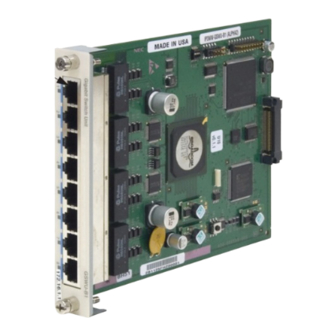
Page 14: Indicators, Switches And Connectors
Revision 1 UX5000 ___________________________________________________________________________________ ECTION NDICATORS WITCHES AND ONNECTORS Refer to Figure 2-1 GSWU Blade for LED and switch locations. RJ45 Connector (x8) Activity LED (x8) Figure 2-1 GSWU Blade LED Indicators The LEDs for each port indicate of the status of an activity. -
Page 15: Connectors
UX5000 Revision 1 ___________________________________________________________________________________ Connectors The following connectors are used: ❍ J1 (Backplane Connector) This connector is used to connect to the CCPU blade or other blades in the chassis. ❍ J5 (Ethernet Ports) There are eight ports for 10/100/1000 Mbps Ethernet connectivity. - Page 16 Revision 1 UX5000 ___________________________________________________________________________________ -- NOTES -- ___________________________________________________________________________________ 2 - 4 GSWU Blade...
-
Page 17: Gswu Blade Setup
GSWU Blade Setup GSWU B ECTION NSTALLING THE LADE System Requirements This blade can be installed in any universal slot in the controlling chassis (slots 2~6) and expansion chassis (slots 7~24). Installation and Safety Precautions Observe the following precautions when installing the blades to avoid static electricity damage to hardware or exposure to hazardous voltages. -
Page 18: Installing The Gswu Blade In The Chassis
Insert the blade within the guide rail and push the blade securely into position. Tighten the thumb screws on either side of the blade. Figure 3-1 Inserting Blades in the Chassis UX5000 P ECTION ROGRAMMING The GSWU blade can be programmed using a Multiline Terminal, PCPro or WebPro. - Page 19 UX5000 Revision 1 ___________________________________________________________________________________ Access PRG 10-55: Blade Network Setup to set the network information for the GSWU blade. ❑ 10-55-01 IP Address ❑ 10-55-03 Main/Add-on This program option is very important. When the GSWU blade is utilized, it obtains its Networking information according to the settings in data programs 10-55-01~10-55-05.
- Page 20 Revision 1 UX5000 ___________________________________________________________________________________ -- NOTES -- ___________________________________________________________________________________ 3 - 4 GSWU Blade Setup...
-
Page 21: Gswu Blade Configuration
GSWU Blade Configuration GSWU B ECTION ONFIGURING THE LADE When installed for the first time, the GSWU blade comes up with the factory default parameters shown in Table 4-1 Network Settings for TCP/IP Addressing. Table 4-1 Network Settings for TCP/IP Addressing IP Address 172.16.1.100 Subnet Mask... - Page 22 Revision 1 UX5000 ___________________________________________________________________________________ To configure the PC: Press Start and select Control Panel from the menu. Windows XP Professional operating system is used in this example. When using a different Windows operating system, the screens may look slightly different.
- Page 23 UX5000 Revision 1 ___________________________________________________________________________________ On the Control Panel menu, double click on Network Connections Figure 4-2 Control Panel Screen From the Network Connections screen, double click on Local Area Connection. Figure 4-3 Network Connections Screen ___________________________________________________________________________________ Gigabit PoE Switch Manual...
- Page 24 Revision 1 UX5000 ___________________________________________________________________________________ When the Local Area Connection Status screen is displayed, click the Properties button. Figure 4-4 Local Area Connection Status Screen From the Local Area Connection Properties screen, select Internet Protocol (TCP/IP) and then Properties. Figure 4-5 Local Area Connection Properties Screen...
- Page 25 UX5000 Revision 1 ___________________________________________________________________________________ Click on Use the following IP address. For this example, enter 172.16.1.99 for the IP address and 255.255.255.0 for the Subnet mask. Click OK to accept the changes. Figure 4-6 Internet Protocol (TCP/IP) Properties Screen On the Local Area Connection Status screen, click Close, then close the...
- Page 26 Revision 1 UX5000 ___________________________________________________________________________________ -- NOTES -- ___________________________________________________________________________________ 4 - 6 GSWU Blade Configuration...
-
Page 27: Gigabit Poe Switch Web Manager
Gigabit PoE Switch Web Manager (GSWU B ECTION OGGING IN TO IGABIT WITCH LADE The GSWU blade is configured using an Internet Browser. Microsoft Internet Explorer 6.0 or higher is recommended. The Login screen allows a user to enter their user name (admin) and password (password) for web management access. -
Page 28: Home Menu
Revision 1 UX5000 ___________________________________________________________________________________ ECTION After a technician logs into the GSWU blade web-interface, the Home page or Main Menu is displayed. This menu provides access to the configurable settings and administrative functions available for the GSWU blade. This menu is split into three regions and an informational sidebar. - Page 29 UX5000 Revision 1 ___________________________________________________________________________________ ❑ Administration – This section of the screen allows access to the following functions: ❍ Firmware Download (refer to Figure 5-9 Firmware Download Screen on page 5-13 Figure 5-10 Firmware Download Screen on page 5-14) ❍...
-
Page 30: Port Link Status
Revision 1 UX5000 ___________________________________________________________________________________ ECTION TATUS This screen shows the connection status for each Ethernet port. Click Refresh if your web page cannot be displayed or to ensure the latest version of the page is displayed. Click Home to return to the Home Menu. -
Page 31: Section 4 Port Configuration
UX5000 Revision 1 ___________________________________________________________________________________ ECTION ONFIGURATION The port configuration page shows the settings for each of the Switch’s ports. Port – The number of the port. Admin State – The port can be taken offline by selecting the disable option. When enabled the port can be accessed as normal. - Page 32 Revision 1 UX5000 ___________________________________________________________________________________ Figure 5-4 Port Configuration Screen ___________________________________________________________________________________ 5 - 6 Gigabit PoE Switch Web Manager...
-
Page 33: Poe Settings
Power (mW) – Power consumption in milliWatts. Indicates the amount of power consumed by the device. For additional information on the amount of watts consumed by NEC Terminals. Reference the UX5000 Hardware Manual, P/N 0913100. ___________________________________________________________________________________ Gigabit PoE Switch Manual... -
Page 34: Section 5 Poe Settings
Revision 1 UX5000 ___________________________________________________________________________________ Click Apply to accept the changes. Click Refresh if your web page cannot be displayed or to ensure the latest version of the page is displayed. Click Home to return to the Home Menu. Figure 5-5 PoE Settings Screen... -
Page 35: Section 6 Port Mirroring Configuration
UX5000 Revision 1 ___________________________________________________________________________________ ECTION IRRORING ONFIGURATION This screen allows users to monitor entry/exit traffic using a single port (designated as a Mirror Port). Port mirroring monitors and mirrors network traffic by forwarding incoming and outgoing packets from one port to another port. Port Mirroring can be used as a debugging tool. -
Page 36: Section 7 Port Pvid
Revision 1 UX5000 ___________________________________________________________________________________ PVID ECTION This screen allows users to assign priorities to the VLAN ID ingress ports. The Port PVID screen provides parameters for managing ports that are part of a VLAN. Port – defines the GSWU port 1~ 8 included in a VLAN. - Page 37 Add/Modify VLAN Designate the new VLAN ID Adding new VLAN ID This is to ensure priority treatment of the VoIP traffic by the UX5000. Click Apply to accept the changes. Click Refresh if your web page cannot be displayed or to ensure the latest version of the page is displayed.
-
Page 38: Section 8 Vlan Configuration
Revision 1 UX5000 ___________________________________________________________________________________ Figure 5-8 VLAN Configuration Screen ___________________________________________________________________________________ 5 - 12 Gigabit PoE Switch Web Manager... -
Page 39: Firmware Download
Once you have browsed for the file select Send. Selecting the Cancel button will stop the action. This firmware is provided by NEC and must be stored locally prior to selecting the Send button. Click Refresh if your web page cannot be displayed or to ensure the latest version of the page is displayed. - Page 40 Revision 1 UX5000 ___________________________________________________________________________________ The firmware update will begin when this window is displayed. The window will count down to zero and restart the GSWU once the update process is complete. Do not power off the system while the upload is in progress.
-
Page 41: Section 10 Session Management
Default Gateway – Enter the address of the Default Gateway Manually setting the networking address is not ❍ recommended. The UX5000 system supports the use of Programs 10-55-01 ~ 10-55-05. A reboot is required before the new changes become ❍... - Page 42 Revision 1 UX5000 ___________________________________________________________________________________ Figure 5-11 Session Management Screen ___________________________________________________________________________________ 5 - 16 Gigabit PoE Switch Web Manager...
-
Page 43: Section 11 Initialization
UX5000 Revision 1 ___________________________________________________________________________________ ECTION NITIALIZATION This screen allows users to initialize the NVRAM to the default setting and the allows the GSWU blade to be rebooted. Reset NVRAM to Defaults – When selected will restore factory default setting removing any previously stored information (Site name, VLANs, Port Mirroring, etc.). - Page 44 Revision 1 UX5000 ___________________________________________________________________________________ -- NOTES -- ___________________________________________________________________________________ 5 - 18 Gigabit PoE Switch Web Manager...
-
Page 45: Chapter A Glossary
Glossary __________________________________________________________________________________ ECTION NTRODUCTION The following terms are used in this document. The term or acronym is listed as well as the associated definition. The terms are listed in alphabetical order. ECTION ERMS AND EFINITIONS Term Definition Ethernet Ethernet is a family of frame-based computer networking technologies for local area networks (LANs). - Page 46 Revision 1 UX5000 ___________________________________________________________________________________ Term Definition Real-Time Transmission Real-Time Transmission is transmission in which there is no perceived delay in the transmission of a voice message or the response to it. This is a requirement for voice traffic. Subnet Mask A number used to identify a subnetwork so that an IP address can be shared on a LAN.
- Page 47 NEC Unified Solutions, Inc. 4 Forest Parkway Shelton, CT 06484 www.necux5000.com Important Telephone Numbers Sales Support and General Information 800-365-1928 ....
- Page 48 NEC Unified Solutions, Inc. 4 Forest Parkway Shelton, CT 06484 www.necux5000.com (See inside back cover for contact information.) (0913101) Printed in U.S.A. July 10, 2008, Rev 1...
Need help?
Do you have a question about the UX5000 and is the answer not in the manual?
Questions and answers