Advertisement
Quick Links
INSTRUCTIONS for
REMOTE CURRENT AND CONTACTOR CONTROL
This remote control is designed for use with any
power source that employs a single (common) cur-
rent and contactor control 14-pin Amphenol recep-
tacle. It contains a potentiometer which controls the
current output when the Panel/Remote Switch (PRS)
on the power source is placed in the "Remote"
position. This remote control also consists of a
switch when the PRS is placed in the "Remote"
position. Both the potentiometer and switch are
operated when the FC-5C pedal is depressed. See
the schematic diagram in your respective power
source instruction literature.
Interconnection of these functions to the main power
source is provided by a single mating 30-ft. cable/
plug assembly provided.
Make sure all primary power to Power Source is disconnected before installation of these plugs.
G
H
F
N
K
E
M
L
D
C
B
FACE VIEW
BLUE
BROWN
RED
WHITE
BLACK
(SW Closed)
SCHEMATIC DIAGRAM
Treadle In Down Position
Revision OR
05 \ 2003
0558004303
Printed in U.S.A.
FC-5C FOOT OPERATED
WARNING
!
I
J
A
P 1
E
F
G
D
B
A
12 / 2004
By depressing the foot pedal, the weld start sequence
circuit will energize, and the welding current will in-
crease or decrease semi-linearly within the range pre-
set on the power source "Current" control potentiom-
eter.
To use the remote control, proceed as follows:
1. Plug the FC-5C control cable into current/contactor
control receptacle on the power source.
2. Set the Remote/Panel toggle switch to the Remote
position.
3. Set the Current Control on the power source panel to
the maximum current range to be used.
4. Depress foot pedal as desired to weld.
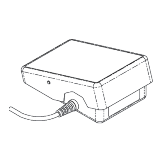
FC-5C Foot Control Assembly (30 ft.)
ESAB P/N 0558004234
ESAB
ESAB Welding & Cutting Products
PO Box 100545, Florence SC 29501-0545
Advertisement

Subscribe to Our Youtube Channel
Related Manuals for ESAB FC-5C


Summary of Contents for ESAB FC-5C
- Page 1 To use the remote control, proceed as follows: switch when the PRS is placed in the "Remote" position. Both the potentiometer and switch are 1. Plug the FC-5C control cable into current/contactor operated when the FC-5C pedal is depressed. See control receptacle on the power source.
- Page 2 0558004242 Compression (Rack) Spring 0558004243 Convoluted Sleeving 0558004244 Rack Housing with Screws 0558004245 Strain Relief Bushing 0558004246 Pot - 10K LIN, 2W High Life FC-5C 0558004247 Cable FC-5C per Foot (30) 952248 Plug, 14 Pin Male 23601944 Clamp, Cable 0558004303...
Need help?
Do you have a question about the FC-5C and is the answer not in the manual?
Questions and answers