
Related Manuals for ESAB ER 1


Summary of Contents for ESAB ER 1
- Page 1 ER 1, ER 1F Remote controls Service manual Valid for: 716-xxx-xxxx 0463 480 001 GB 20170607...
-
Page 2: Table Of Contents
Unable to increase current with ER 1F........... Status indications on circuit boards ............Remote control board 21AP1 – Indication of operational status .... DISASSEMBLY AND REASSEMBLY ............ER 1 ......................ER 1F ......................SPARE PARTS AND ACCESSORIES ............. Rights reserved to alter specifications without notice. -
Page 3: Read This First
The ER 1 and ER 1F are designed and tested in accordance with the standards stated in the instruction manual. On completion of service or repair work, it is the responsibility of the person(s) performing the work to ensure that the product still complies with the requirements of the involved standards. -
Page 4: Before Starting Service
BEFORE STARTING SERVICE BEFORE STARTING SERVICE Service aid ESAB can offer a number of service tools that will simplify the service. Antistatic service kit Ordering no. 0740 511 001 The kit makes it easier to protect sensitive components from electrostatic discharge. -
Page 5: Introduction
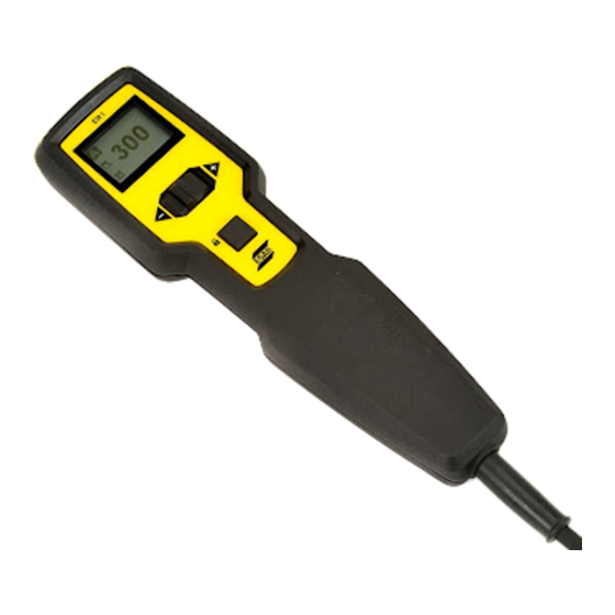
INTRODUCTION INTRODUCTION The remote control ER 1 can be used to control current, arc force and memory selection. The available functions and number of memories depend on the power source the remote control is connected to. The foot pedal ER 1F can be used to control current. It also has a trigger function, which can be used for weld start. -
Page 6: Technical Data
Weight unit with 5 meter 475 g (1.05 lb) 2250 g (4.96 lb) (16.4 ft) cable Operating temperature -20 to +60 °C (-4 to 140 °F) -20 to +60 °C (-4 to 140 °F) Transportation temperature -40 to +80 °C (-40 to 176 °F) -40 to +80 °C (-40 to 176 °F) Enclosure class IP53 IP23 0463 480 001 - 6 - © ESAB AB 2017... -
Page 7: Wiring Diagram
21XS3 Encoder 21AP1 Control board 21XS1 Remote interconnection cable Block diagram NOTE! 21AP1 is same but used with different configuration for remote control ER 1 and foot pedal ER 1F. ER 1 0463 480 001 - 7 - © ESAB AB 2017... - Page 8 WIRING DIAGRAM ER 1F 0463 480 001 - 8 - © ESAB AB 2017...
-
Page 9: Software
The software in ER 1 and ER 1F consists of three parts: system software (application software), secondary bootloader and primary bootloader. The software is updated using the USB port on the power source. For information about software update, see power source service manual. 0463 480 001 - 9 - © ESAB AB 2017... -
Page 10: Error Codes
Value (in V DC) TP35, TP2 11.25 V ≤ V ≤ 11.85 V 4.5 V ≤ V ≤ 5.5 V 3.13 ≤ V ≤ 3.47 ER 1F: TP12 2.75 ≤ V ≤ 2.90 0463 480 001 - 10 - © ESAB AB 2017... - Page 11 ERROR CODES 0463 480 001 - 11 - © ESAB AB 2017...
-
Page 12: Troubleshooting
The trigger does not work Check if the micro switch trigger is mechanically stable. If not, replace the complete unit. Check the voltage at the test points. If the values deviate replace 21AP1. 0463 480 001 - 12 - © ESAB AB 2017... - Page 13 Foot pedal in fully CN9.2 w.r.t CN5.2 Voltage at TP9 wrt. 0.29 ±0.3 V DC released state. TP3 (GND) Foot pedal in fully CN9.2 w.r.t CN5.2 Voltage at TP9 wrt. 3.27 ±0.3 V DC pressed state. TP3 (GND) 0463 480 001 - 13 - © ESAB AB 2017...
-
Page 14: Status Indications On Circuit Boards
Note! These type of error does not include the communication interface since that is separately indicated. (1 Hz flash) No communication path has been established or some other error has occurred in the communication system. 0463 480 001 - 14 - © ESAB AB 2017... -
Page 15: Disassembly And Reassembly
To replace magnets, place the back cover on a metal surface and remove the screws. Remove the interconnection cable 4. Remove the two screws (3). 5. Remove the connectors. 6. Place the aluminium tape on the cable below the metal plate. 0463 480 001 - 15 - © ESAB AB 2017... - Page 16 9. Remove the three screws holding the circuit board and remove the board. If needed, replace the LCD on the front cover. Reassemble the remote control in the reverse order using the correct tightening torques according to the illustrations. 0463 480 001 - 16 - © ESAB AB 2017...
-
Page 17: Er 1F
Remove the screw connecting the shield of cable to the metal plate used for mounting the PCBA (4). Replace the cable. Insert the connectors (3). Ensure that the IP protection sheet is covering the PCBA and connectors. Replace the top cover. 0463 480 001 - 17 - © ESAB AB 2017... -
Page 18: Spare Parts And Accessories
Spare parts list 0059 576 990 MTA1 CAN, M1 10P CAN, AT1 CAN, AT1 CF CAN, M1, AT1, AT1 CF, RA 12, RA 23, RA T1, FS 002 CAN, FS 002, T1 Foot CAN, ER 1, ER 1F Instruction manual 0463 471 * ER 1, ER 1F 0463 480 001 - 18 - © ESAB AB 2017... - Page 19 SPARE PARTS AND ACCESSORIES 0463 480 001 - 19 - © ESAB AB 2017...
- Page 20 ESAB subsidiaries and representative offices Europe THE NETHERLANDS North and South America SOUTH KOREA ESAB Nederland B.V. ESAB SeAH Corporation AUSTRIA Amersfoort ARGENTINA Kyungnam ESAB Ges.m.b.H Tel: +31 33 422 35 55 CONARCO Tel: +82 55 269 8170 Vienna-Liesing Fax: +31 33 422 35 44...
Need help?
Do you have a question about the ER 1 and is the answer not in the manual?
Questions and answers